I have probably said a number of times so far, how impressed I am with Don's design and how accurate it is in following the prototype, the handbrake is just one of those very clever designs which are seen throughout Gresley's Pacific's. Probably not unique to this class and unlikely to have been drawn/designed by the great man himself but it is an interesting piece to make, non the less.
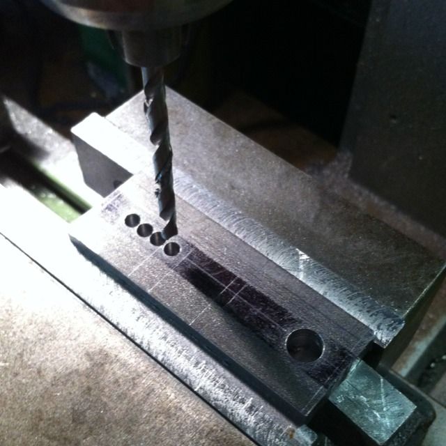
I began with the handbrake link, here is the first stage of its construction. A 2 3/4 length of 1"x 5/16 BMS flat bar is held in the vice, first a 5/16 hole is drilled on the center-line to match the hole in the brake shaft. Then a number of No.24 holes are drilled in preparation for the 3/4 x 5/32 slot which was next milled.
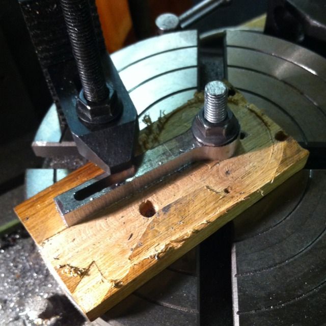
With the slot milled next job was to profile the link on the rotary table. I machined around the 5/16 hole first followed by the sides and end.
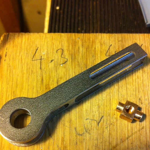
I seem to have missed some pictures but here's the finished link and nut. The link also has two slots on the other face with a 1/8 section left between them as can be seen in this picture if you look closely. These where done again in the machine vice by holding the link level, holes drilled and then finished using endmills. The slots are of two different sizes, 3/16 for the nut and 5/32 to slide over the right hand brake shaft leg. The nut is from 5/16 bronze rod, chucked in the 3 jaw ,faced,turned down to 5/32 for an 1/8. ( drawing said 1/16 but I wanted to play safe and reduce the risk of the nut sliding out of the link since it's not physically held in) and then parted off at 5/16 overall. Reverse in chuck, and repeat for the other spigot. Two flat spots where then machined on the centre section to allow the nut to slide into it's 5/32 slot. Last job was to remove from the lathe, centre pop the middle section, drill No. 29 and tap 5/32 x 40 T.
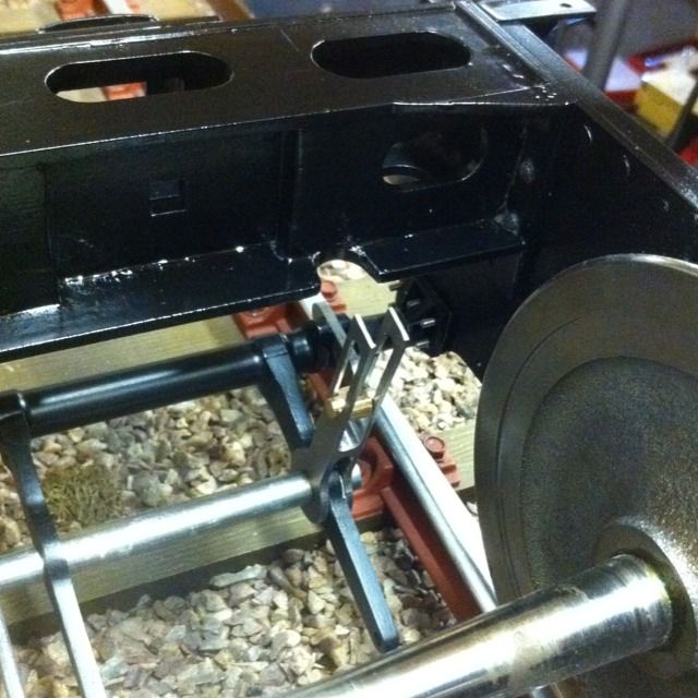
Here we see the link temporarily fitted to brake shaft, now here I came across an error on the drawing that although no big deal was a bit disappointing. If you look closely you'll notice that part of the drag box has been ground out, it turns out that the top and bottom plates for the box should be switched so that the link has the clearance needed. I rechecked the drawing in case I had misread it but I haven't the drawing shows it as built. i think its not so much an error as the way that the box is drawn, ie, it's drawn upside down and thus confusing, well it certainly confused me and i know of some others who also fell for Don's cunning trap. Like I said it's no big deal but for anyone else wishing to build her, take note...
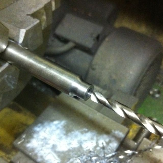
The start of the bearing housing, this is 7/16 BMS, first turned down 5/16 over a 9/32 length using a round nose tool to give it it's curved profile. Then centred and drilled No.11, parted at 1/2 overall then reversed in the chuck, faced, drilled 5/16 for short distance and then finished to a depth of 3/16 with a slot drill. Yes I know I should make a D bit for this job but it's not critical and was only for a short depth.
Now this is an extra piece, the drawing just has a flat piece as the housing bracket but in the close up pictures that I have this is in fact a right angle, which is what you see here.
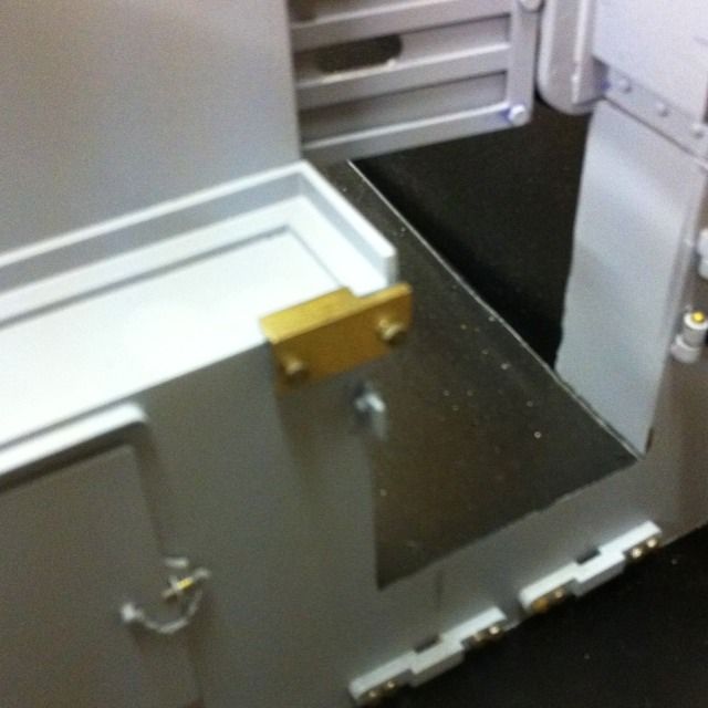
The finished housing in place, the bearing housing having been silver soldered to it's face plate.
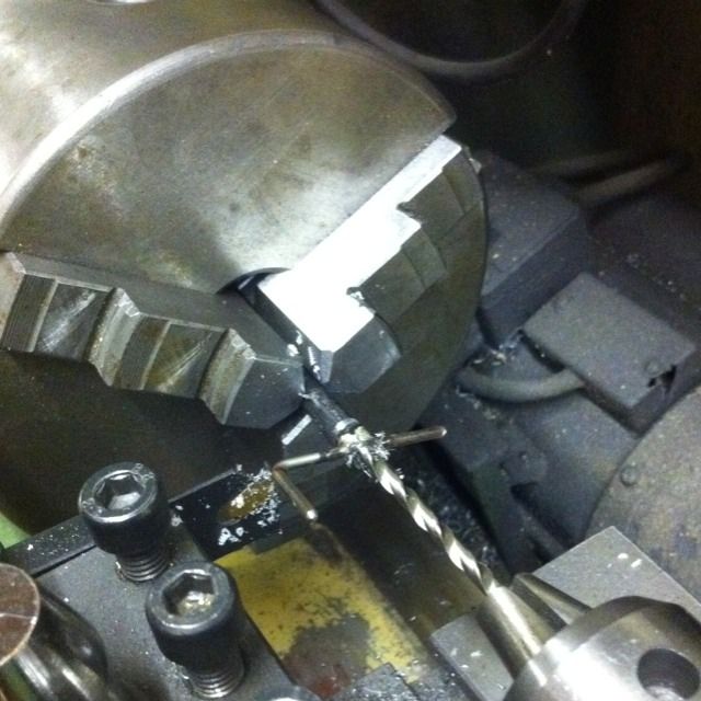
Next up was the handle ,built as suggested by Don, a piece of 1/4 steel is cross drilled to accept a 3/32 rod( I used stainless here to match the polished look of the prototype) which are then brazed together. The rod was over length to allow for it being bent to shape before cutting to final size. The job was then held in the 3 jaw and machined down to the top of the 3/32 rod. Then it was drilled at No.28 to 1/4 depth before parting of at 3/16 overall. BTW drilling through steel with a stainless cross piece is ok if using a very sharp bit and taken slowly...
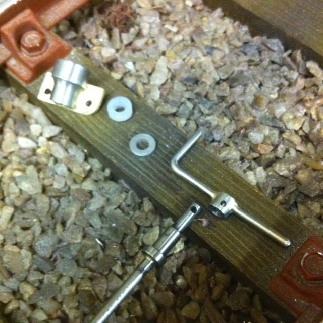
here we see the finished components ready for assembly. Other parts shown here are the spindle which I decided to make in three pieces, consisting off a 1 1/2 length of 5/32 rod threaded to 32 T, a plain 4 1/2 length of 1/8 rod although I added a spigot either end to align with the other two sections. Finally the top piece which has the collar and spigot to fit both the bearing housing and the handle. Last was the thrust washer which consisted of a 5/16 x 1/16 washer and 5/16 x 1/8 PTFE bush, the washer was plain turning, as was the bush but I had no PTFE to hand but did have some similar in the kitchen in the form of a plastic cutting board which just happened to be made of a suitable material, machined nice too, mind you don't think SWMBO was too impressed.
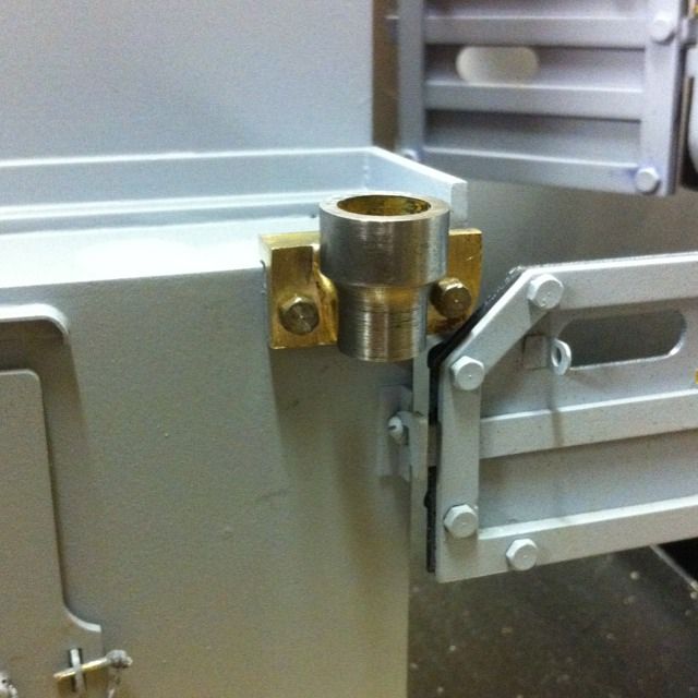
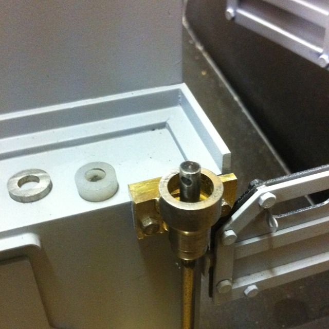
Close up of bearing housing with spindle inserted and washer and bush ready for fitting.
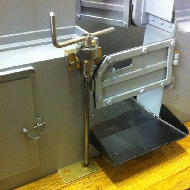
The finished handbrake which I'm happy to report works perfectly... the brass bolt was changed later for a pin