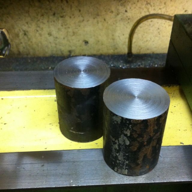
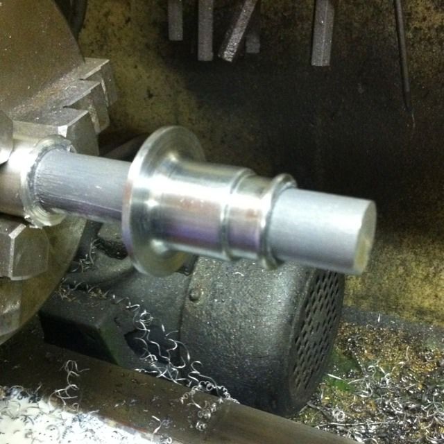
These are made from solid and begin life as lumps of steel cut to 3" lengths ready for machining the buffer stocks. I'm not sure what steel this was as it was an old 2' length of 1 3/4" bar that my son brought home for me from work, but one thing is sure, it's tough stuff..
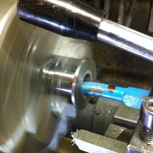
With the basic outside shape/profile having been machined first I then reversed the part in the chuck and bored each buffer stock in turn out to size, ready for the buffer heads to fit later.
With the basic turning/boring completed I turned up an alloy plug to fit so I could lap the bores to finish. I used some fine valve lapping paste for this job.
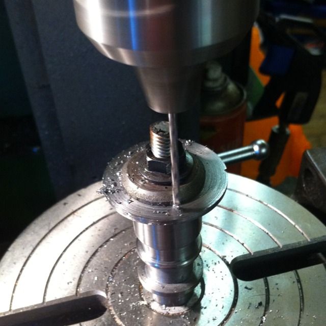
Next the stocks were moved to the rotary table for machining the 4 No.44 holes ready for attaching to the buffer beam. A straight forward job but time consuming as I had to turn down a MT2 soft arbour first and then tap and drill to hold the job securely.
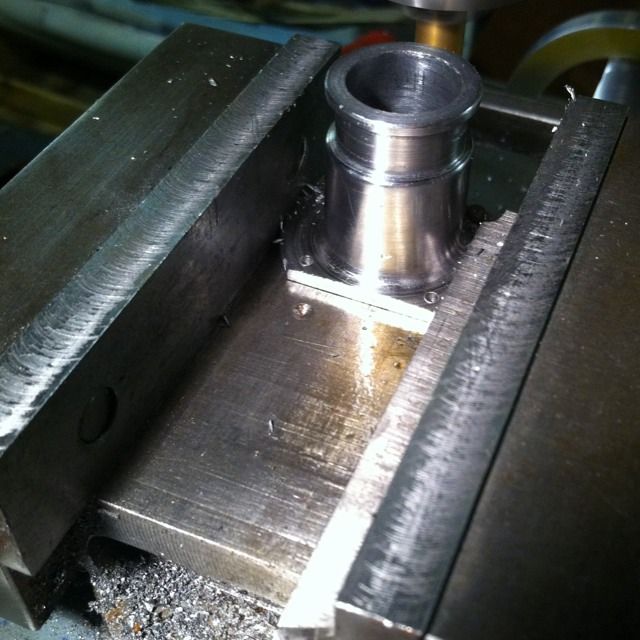
Whilst pondering a jig for holding each buffer stock to machine the flat flanges, it dawned on me that all I needed to do was place two 8BA bolts into the No.44 holes for the face that I wanted to machine and push these against the side face of the machine vice and then tighten up. Once the first flange had been done it was a simple task to clock the job 90 degrees, move one bolt to the next hole and re-tighten in the vice, remembering to fit a spacer for clearance. Doing it this way meant I could leave the mill fixed on one axis and thus machine equal amounts from each face without having to measure each one and thus guarantee that they were all the same..
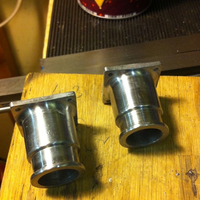
The completed bases bar, polishing to remove machining marks was done after this picture
Then, on to the buffer heads themselves, these started with plain turning of the shaft, buffer stocks tested for a sliding fit and then had a 10 degree angle machined on the back of the head.
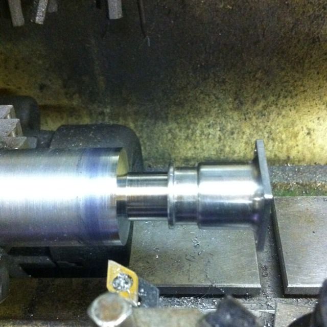
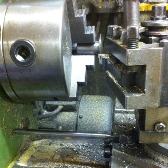
Here the face is seen being machined using the method that I picked up from IIRC reading John Baguley (2 1/2 gauge association) post on one of the engineering forums. As you can see there's a steel bar with points machined each end to act as a pivot, the length of the bar is calculated to give the correct radius of the buffer head by the arc that it forms. The saddle needs to be loose for this to work.
I forgot to take a picture showing the shaft being bored out to accept the spring. Also this then had a hole drilled and tapped 4BA for the securing screw. Another part I forgot to picture is the socket that holds the spring in place, all these parts fit inside the stock so that there's nothing sticking out the back of the housing as this would foul against the frames. I guess I was to busy for pictures of these parts..
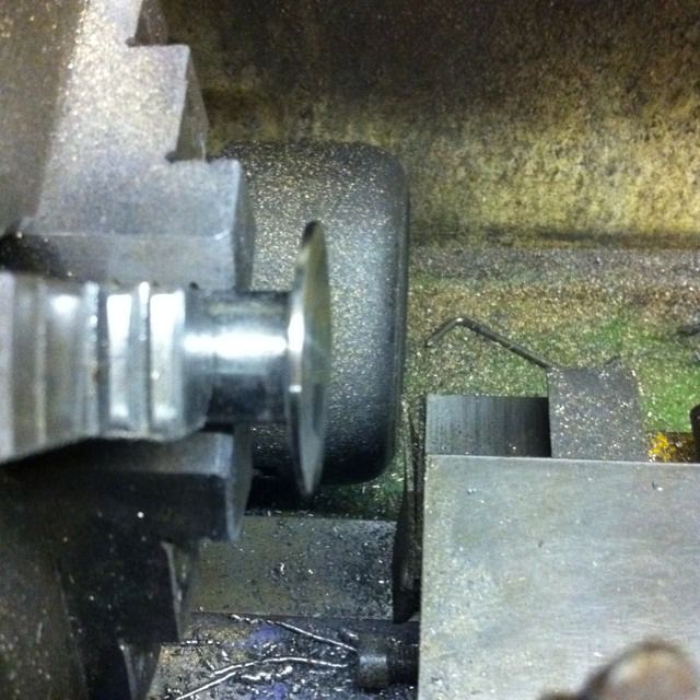
Picture showing the resulting arc of the dish looks
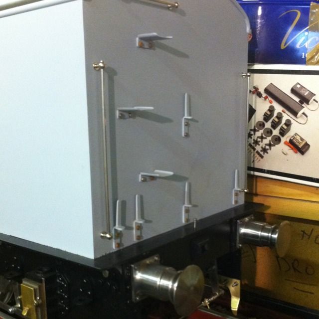
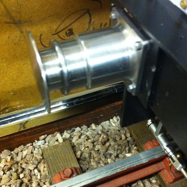
The finished article now temporarily fitted to the buffer beam. As you may notice the frame is directly behind it, hence why the stock needed to contain all of the spring mech to work. If anyone wants details just let me know (until I have a comments section up and running ), for now you can contact me on FB or the MECH forum

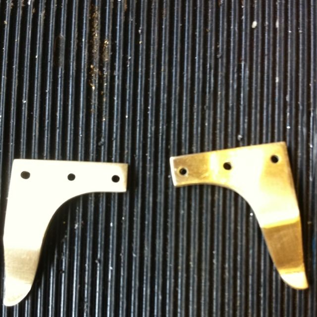
I decided to do the guard irons next. Here are the pair having been cut, filed, drilled (No.44) and bent to shape remembering to make opposites. Don mentions how these things tend to get knocked off and how his drawing states items that are probably a little overkill and could be made more to scale. I think you guys have realised now that scale is important to me so naturally I took that direction. I made these in brass perhaps if they do get knocked their more likely to bend than shear off, time will tell.
Guard irons now fitted to the chassis, the 8BA bolts have been left overlength in this picture as the steps which fit in the same location share the bolts. Those will be shown a little later...