I then directed my attention to the stiffeners that give internal support to the tender sides. I have deviated from Don's instructions as they seem to be just for show rather than prototypical. Don had instructed to add some 3/16x1/16 brass strip held on by 4 3/64 rivets between the brass right angle at coal chute height up to the top of the sides.
Thanks to photo's passed to me of 4472's tender as she is today I could see how it should be, I realise that today's tender is a corridor version whereas I'm building a non corridor but I'm sure most parts will be the same. In the photos there is no sign of rivets so I'm assuming it's welded, it could also be flush riveted but either way the look would be the same.
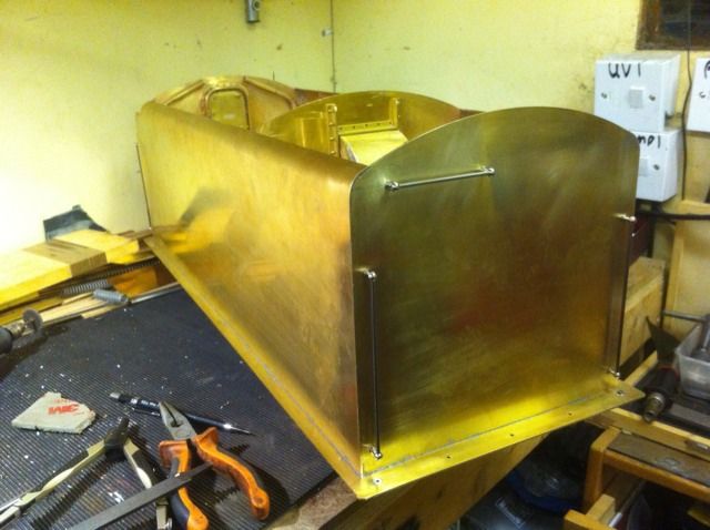
A close up showing some of the stiffeners soldered in place ready for cleaning
here we see all 12 stiffeners fixed and cleaned although the whole body still required a proper clean up before painting. Oh and although you cant see it here I re-positioned the locker hasp's as the doors weren't hanging square which would not do.
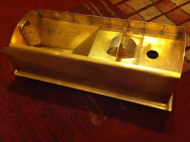
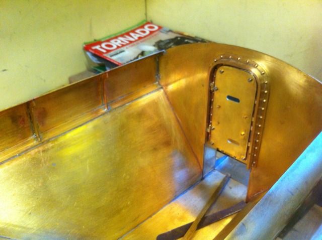
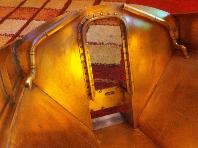
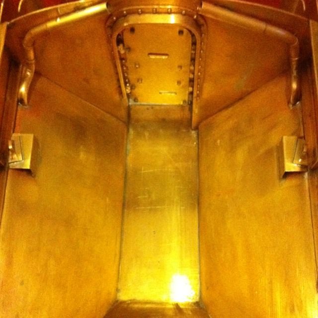
here we have the water vent tubes that Don omitted from his drawings, the photo's that I have are a little unclear when trying to work out the correct shape, I hope I'm not to far away. These were constructed by first heating and bending to shape some brass bar, next was to find some brass tube that slid over this and cut some bands and end pieces to make them look like tubes. Finally the tubes were soldered in place, they are dummies thus taking away any possibility of coal getting into the water and thus risking blocking the loco's two injectors. You can also see here that the tubes sit behind the coal wall rather than as the prototype for my chosen era and 'hooked' over the top.
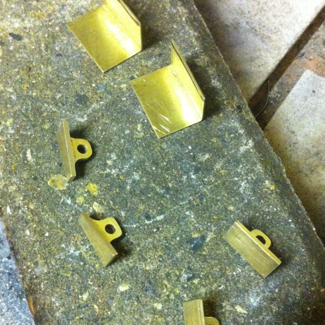
I then tackled the tank lifting lugs , the next few pictures show how I chose to fabricate them.
I started with some 10mm square brass bar, first I machined it to a 'T' section. I then changed to a ball nose slot drill and partitioned the 'T' section to the correct lug size leaving enough material to allow for a parting cut later. The first picture shows this plus the lugs have been drilled and rounded off with a file.
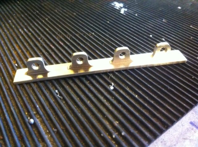
Here the lifting lugs have been divided with the front's having been angled as to drawing. Also the 2 right angled prices of brass have been formed ready to support the front lugs. All were about to be tinned ready for fixing
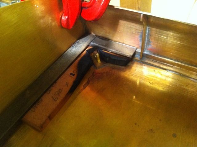
Here we see the rears being soldered in place, they are held in position by an MDF template which can be reversed for doing the opposite side. Oh and the MDF is the grade A fire proof variant ,I saved some scraps from the Wolfman movie where it was used for a 3rd scale model of Chatsworth house that had to be set alight many times without burning down, I also use the same material for my brazing area..The flat steel sections lying on top are to protect the previously soldered sections.
Rear lugs fixed in place, sorry about the poor quality of this particular photo.
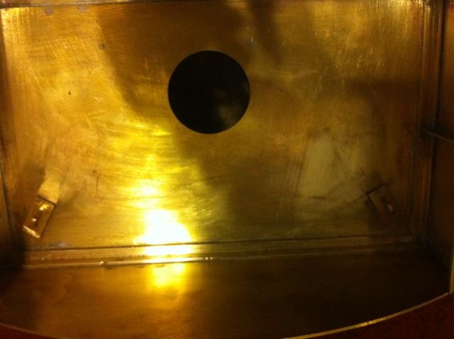
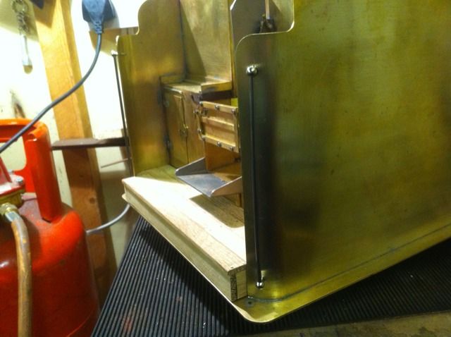
Front lifting lugs/brackets fixed in place.
I then made a start on the handrails , here we have the front. I have used commercial stanchions for these following a call to Maxitrack who kindly measured their stock for the 3 1/2" gauge range, these were perfect and matched Don's drawing perfectly. So for those of you wishing to use commercial fittings and wanting them to be to 5" gauge scale, use the smaller 3 1/2 gauge.
The rear handrails quickly followed, two vertical and a shorter horizontal for the fireman to grab as he climbs the steps which aren't seen in this picture.