
I did a little research on the tank filler lid, Don's drawing is different to the photos that I have which show a much smaller diameter lid than Don's. Also the drawings show a straight cut to separate the two parts of the lid whereas the photos show the lid itself having an angle to it. This makes sense as with a smaller diameter lid it would be impossible to open with vertical sides thus confirming that FS's current lid is indeed smaller. I also found a picture showing the older GN tender with the larger lid, so I'm guessing that it was changed on the later tenders, I could find no info as to when this change occurred. It may well have been after my chosen era of 1938, so my smaller lid following FS as she is today could be wrong, well who's going to know?.. I mean, it's not as if I've advertised the differences...:)
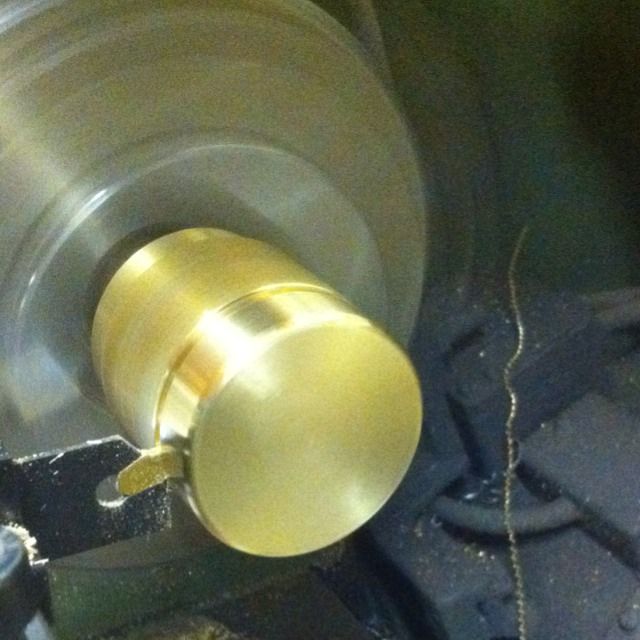
So, onto the work, a piece of brass billet was turned down to size, faced, corners rounded and then parted off
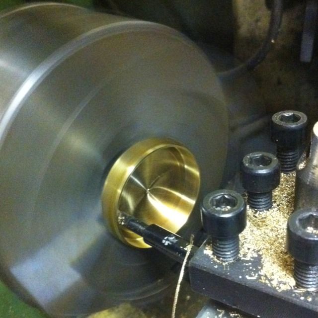
The lid was then reversed in jaws to machine the recess, to stop the lid from getting damaged I wrapped it in some brass shim to protect it. With the lid pushed flat against the jaws and held firming but not to tight this worked well.
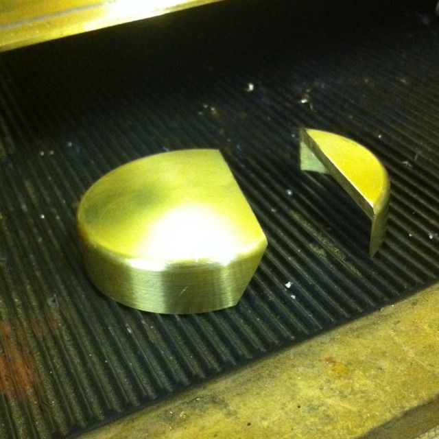
It was then a simple task to Mark out and cut the lid using the bandsaw( it's blade being narrower than my slitting saw) I then set the sanding table at the correct angle and sanded the lid cover to give enough room to be able to open the lid.
I haven't taken pictures for the general components as they are already covered, I have included this picture though as previously I had some thin wall tube of the correct size, this time I didn't..
So here we have some 1/8th brass bar being drilled to a depth of just over 20mm. Normal procedure used, centre drill followed with a 1.5mm drill bit, the drill was set in the chuck with 22mm protruding so it was a simple matter of stopping as the chuck got close to the work piece. Of course I had to do this twice for the parts needed. Parting was a simple matter of removing from the chuck, placing on the bench and rolling under a scalpel blade, hence why the hole was drilled longer than the 20mm needed.
This is the finished hinge , the part attached to the lid was placed so that the pin section was over hanging the edge. The part fixed to the smaller section that will later be brazed to the filler neck was set further in with only a small amount of the pin hanging over the edge. In doing this I could control how the lid will actually open and sit when closed.
The lid is seen here in it's fully open position, had to do a little filing to get the lid to operate correctly but otherwise I was happy with it.
Next up was to make the coupling clasp, here are the components ready for assembly. The coupling clasp is made from stainless steel with brass rings silver soldered to complete. The brass was first drilled as with the hinges and then brazed across the top of the U shaped stainless steel, this was then cut and filed to finish with a 12BA screw. Hinge part was as before and riveted to the hatch lid, the final part being the catch bracket that attaches to the filler neck
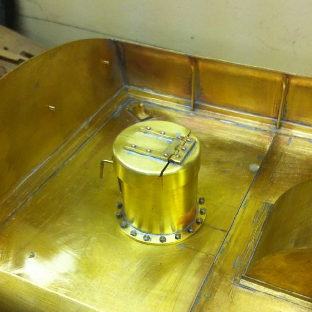
The finished lid was then sweated onto the filler neck and the catch bracket soldered on to stop the lid from flying open if too much water is taken on when using the scoop. not that this would happen on the model as the scoop is one of the very few parts that won'y be functional on this model, I took on board Don's wise words when it came to the scoop. IIRC that being a possible derailment is not worth the risk of fitting a scoop.
