

This entry will be picture heavy as I try to explain Jim's design and also how I have adapted and then made it to fit my model.
For those not familiar with these things and putting aside the various modern materials used these days, the normal practice when making valves and certainly is the case for Don Young's 'Doncaster' drawings is to have a solid bobbin (bronze or cast iron depending on material chosen for the cylinders , most probably use rings) which has the spindle through its centre and then held in position with two nuts either side of the bobbin. This of course means that to fine tune the valve, both covers need removing and the four nuts loosened and retightened when the bobbin is in its correct position. This is a lot of work, the more complicated the model the more work that is involved. Jim Ewins design allows the bobbin to be adjusted by removing just one cover and loosening nuts at one end. Below is an image from Jim's original drawing when published in the Model Engineer in the 80's. I have included this as it helps to show what's going on. There are a variety of designs out there from fellow model engineers based on this but adapted/changed to suit their own needs/ideas. I have done likewise and mine is probably much closer to John Baguley's version, I know that others have done something similar too.

Ok so on to the work at hand and how I have approached this very clever idea. My bobbin carrier's are made from bronze and begun life as a 13" length of 3/4 inch bar, the liner ID is 11/16 (0.6875) and I first turned down the entire length of the bar to 0.665, this gave me a constant length to make all 3 bobbins and the 6 top hats. I'll be using Fluorosint for the rings which is much harder than other plastics with little expansion with a similar expansion rate to bronze. I didn't take a picture of this part but did include this next picture as it helps explain the process ahead. Here I have turned up and bored some bronze to act as a plug and also as a slip gauge. I decided to make the gauge 1 thou oversize (actual size required being 21/64)to trim to size later but as I got going I then changed the size that this gauge was made for, I'll explain this in a minute.
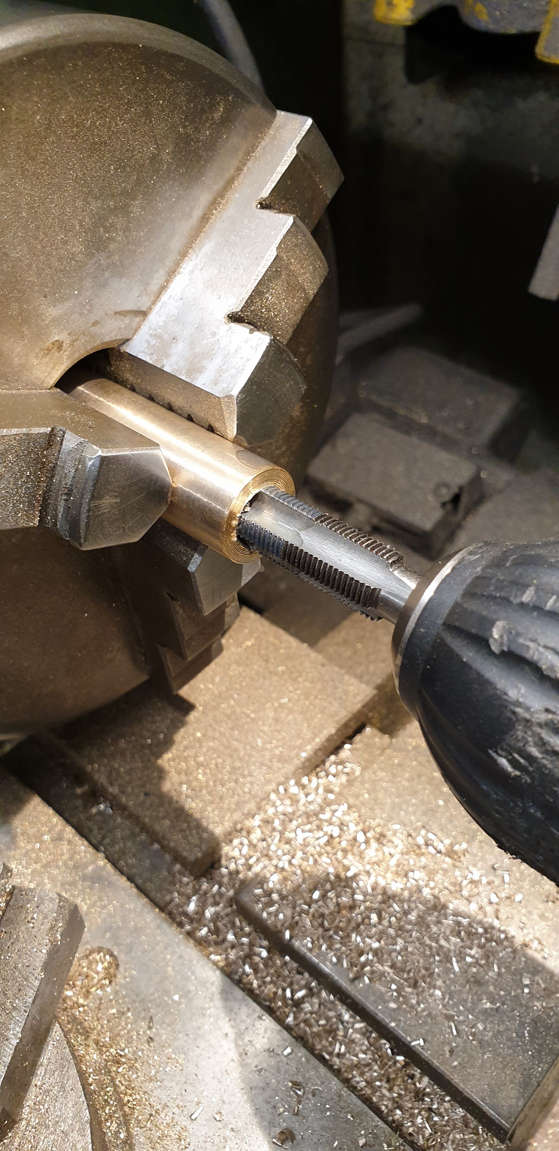
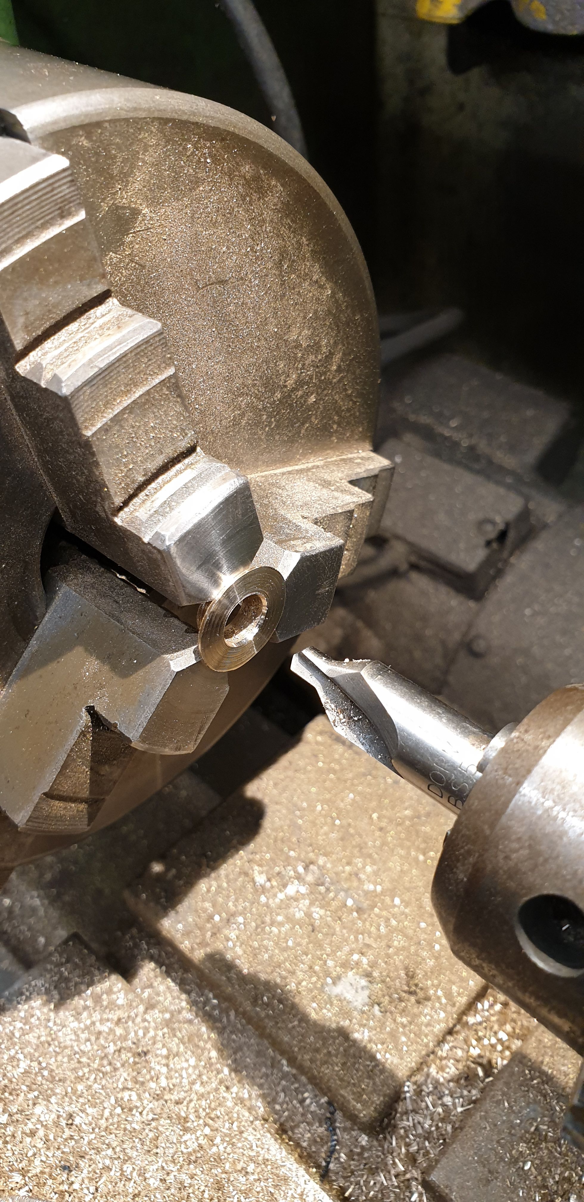
First job to do to the bronze bar was to drill the centre and for my design I decided to make the hole 10.1 mm so that it could be tapped 7/16 x 26 tpi. The sizes that I have chosen were determined by a couple of factors, one I made use of the size taps/dies that I had to hand and two, I chose the sizes to allow the design to fit into the bobbin and spindle OD's, leaving plenty of metal for strength/rigidity. This should become clearer as I get through this entry. This picture shows the first end being tapped 7/16 x 26 tpi.
I then turned down the end for the Fluorosint ring to fit on when machined. Here I chose a journal size of 0.542, this size was chosen to give enough metal for the cut thread below and also to give enough depth to the bush. The length of the journal here is slightly longer than the slip gauge made.
And now the first use of the gauge, here it was used both as a plug for the OD of the journal and also as a gauge for the length of the journal. With the gauge slipped onto the journal I reduced the length until nearly hitting the gauge, stopped, moved the tool up to touch the gauge, removed the gauge and then cut the journal. this is my way of getting them all the same, I currently have no DRO on the lathe and nor can I rely on the dials as I have mentioned on numerous occasions. It was at this stage that I decided to reduce the journal length a little, I'm talking a very small amount, a thou or two. My reasoning is that this will ensure that the top hat when tightened will be tight against the bush and thus no chance of any play which could affect the valve events. The picture shows the gauge/plug sitting over the journal.
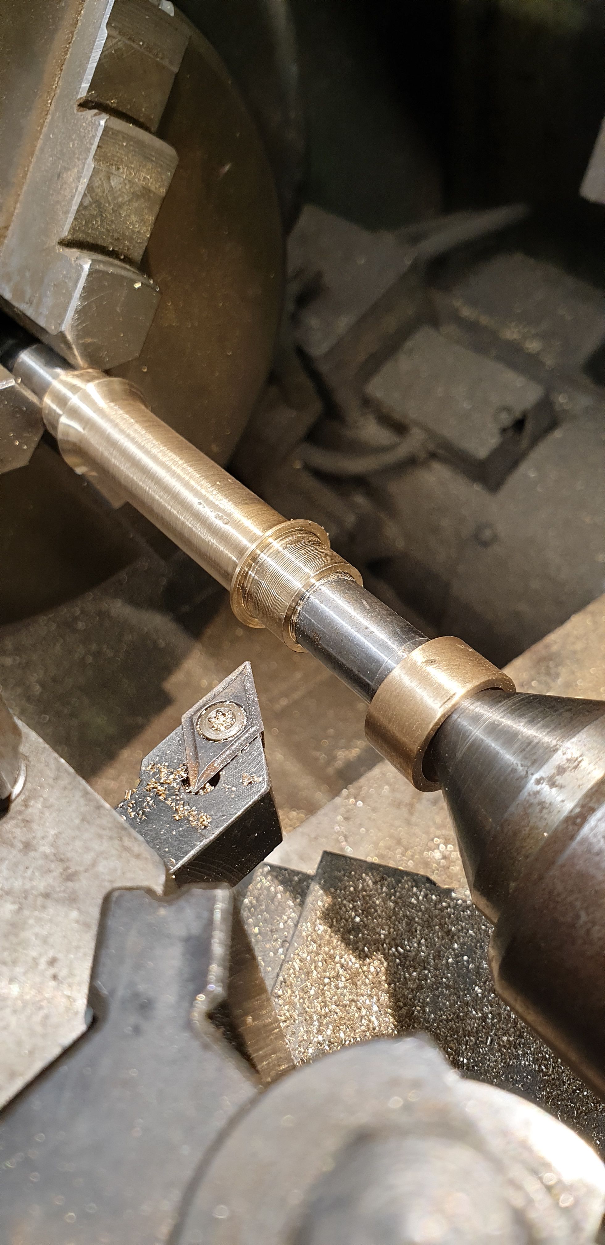
next I pulled the bar out further, noted the critical dimensions, that is the gap between the two bushes and the length of the bobbin (outer port edges)and then machined the middle section using a profile tool. The port outer edges were measured with a tool that i made some time ago when making the liners, I'll show a picture at the end. The picture shows the first stage of doing this ready to machine the other end. I have taken the profile tool up close to the first end, this is to help with the steam/exhaust flow when the ports open/close. The depth of the middle has also been machined thinking about this, it's not yet to size in this picture, this will be finished between centres in a later stage.
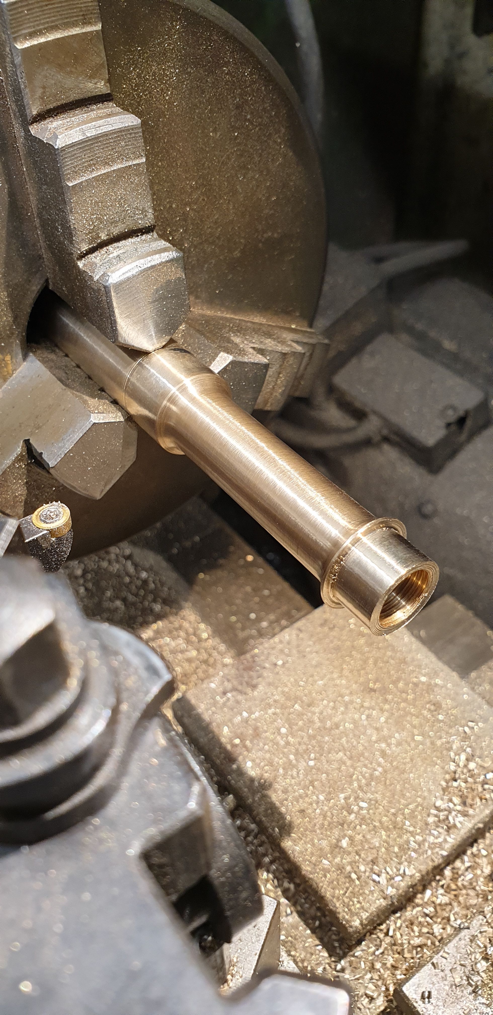
I then pulled the bar out further still, noted the length required for the bobbin 9port outer edge dimension)and made a start on the second journal leaving it both overlength and over size OD, I then parted off.
I then needed to finish the other side, that is cut the thread and machine the journal to size. Before doing this I turned up two 7/16 x 26 tpi threaded lengths of silver steel, threaded one end and deeply centre drilled the other. For the stage seen in this picture one of these was threaded into the first journal so that I could grip the journal without risking damage to it, that is I could hold it well enough to stop it getting knocked out while drilling/tapping the other journal, I still played safe though and took things very slowly. This was a lot easier than it sounds as the hole had already been bored mostly through the entire length of the bobbin.
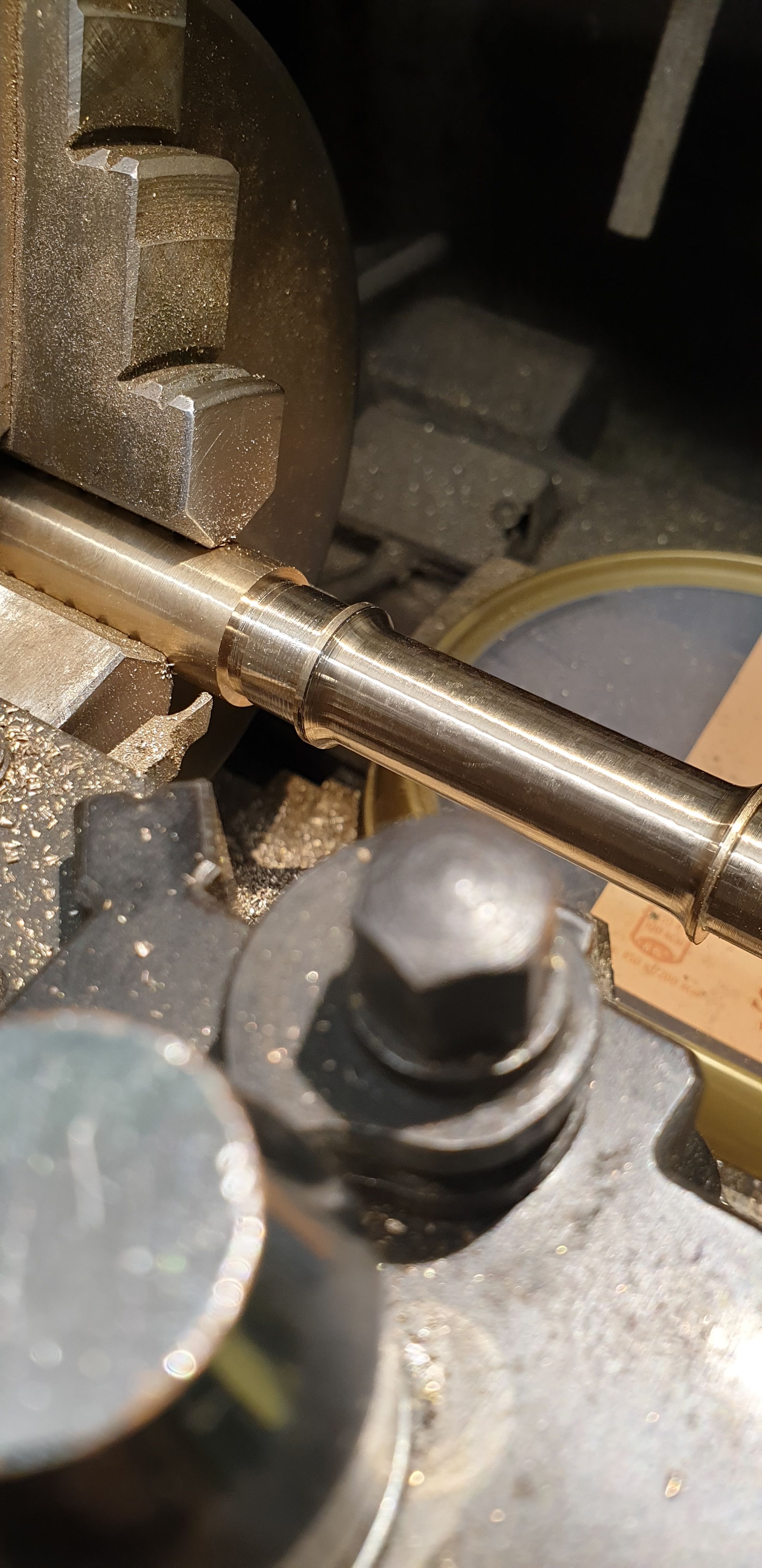
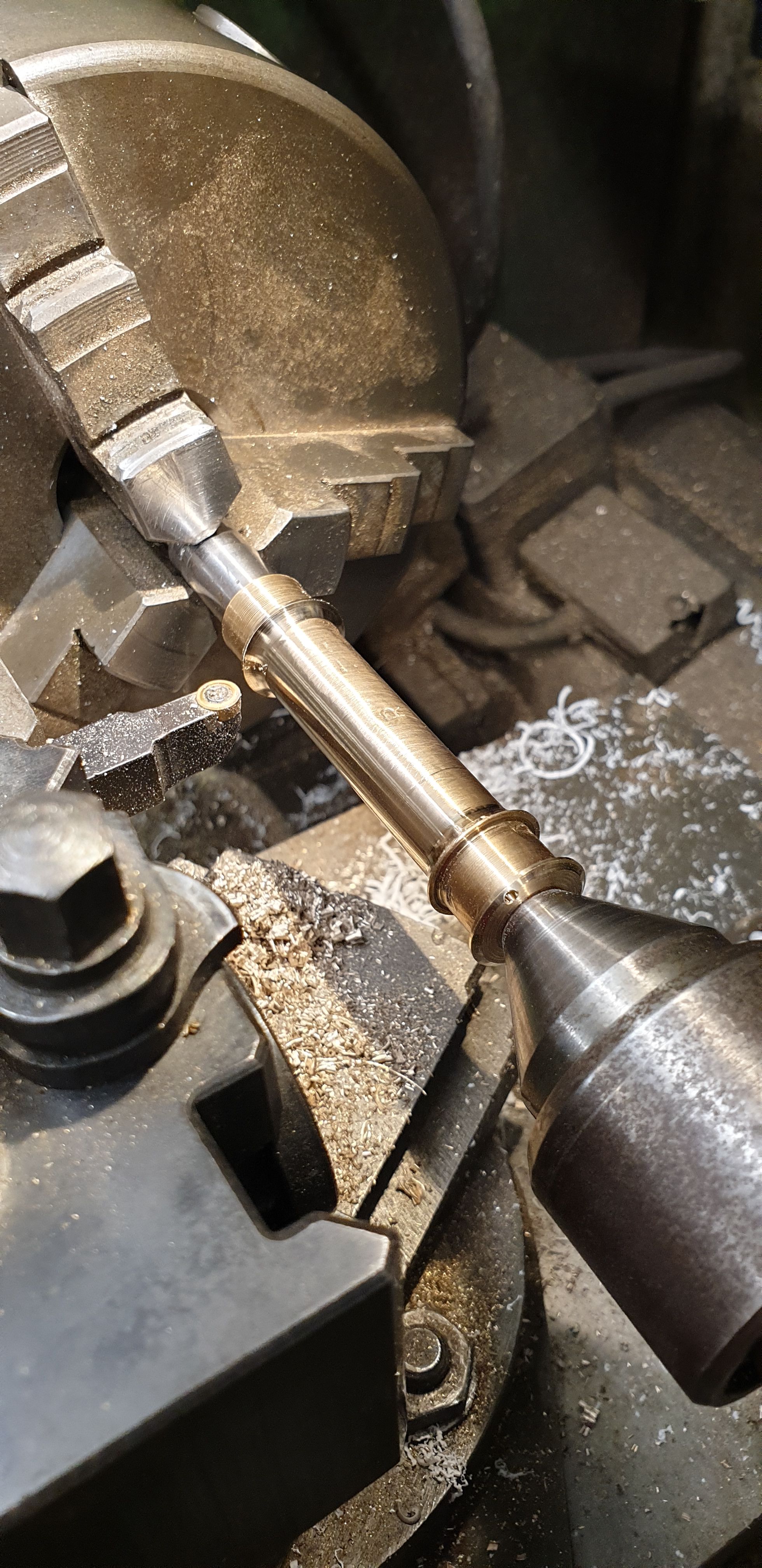
Once I had tapped the second journal, I fitted the other stub and could now hold the bobbin securely between centres. First I reduced the OD of the journal for the plug to fit, pushed the plug onto the journal and began machining to length, as with the first side I did the finish cut by touching the tool up against the gauge with the lathe off. After removing the gauge I advanced the tool another thou to give me the tight fit. Note that the gauge was left floating over the stub so that it could be easily used to check size, note also that the stub this end is longer for this reason.
This picture to show the gauge slipped off the journal for the final cut to size.
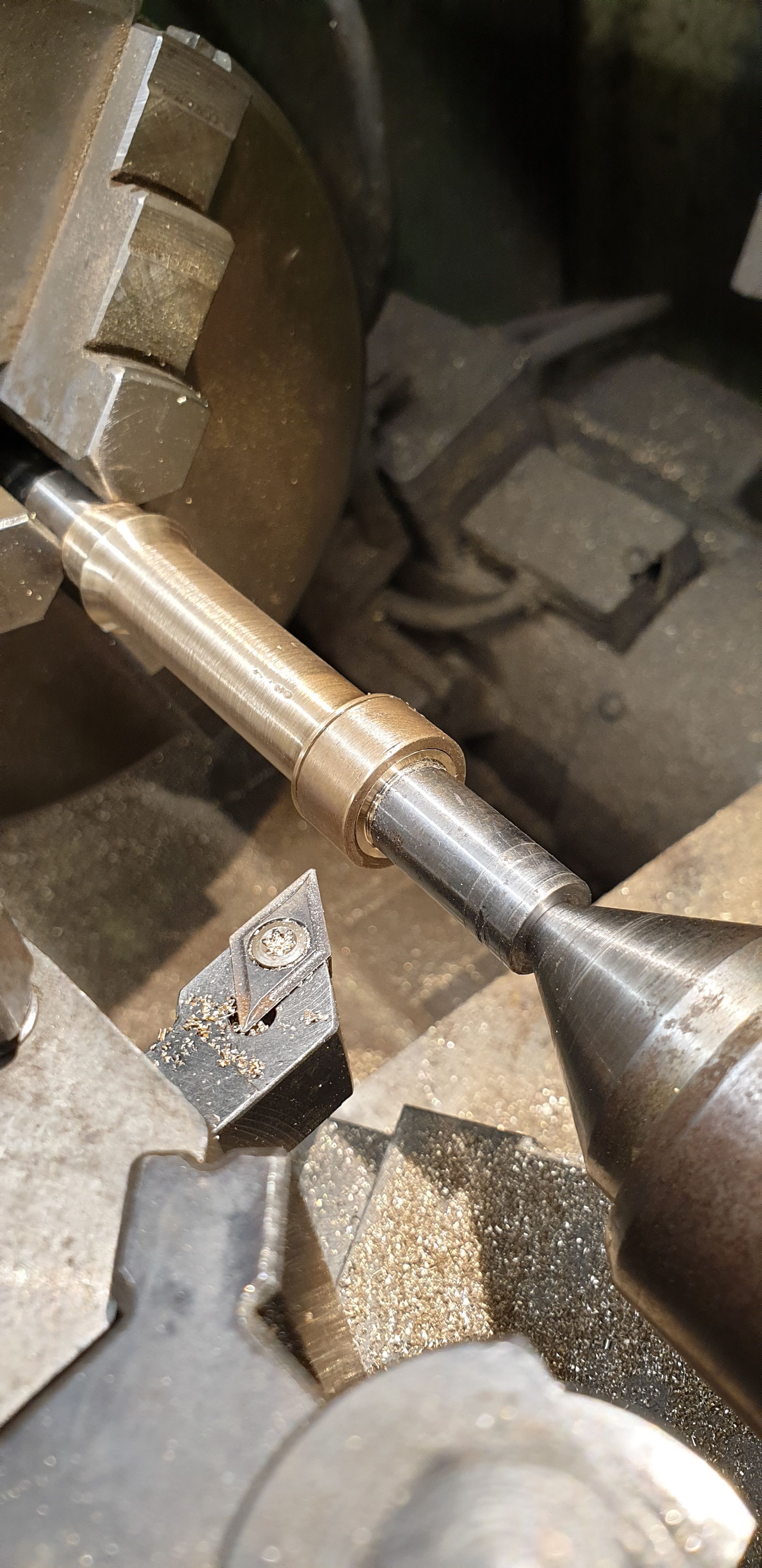
The last thing to do here was to further machine the middle section and take the cut up closer to the other journal and also check for concentricity. My reasoning here is that the bobbin's concentricity relies on the top hats when fitted and thus the tapped threads, the spindle will only touch the top hats, not the bobbin carrier itself, IE the top hats will be what floats on the centre bolt which sits on the spindle and will be made to allow the bobbin to float co-axially as their bores will be slightly larger than the bolt OD.
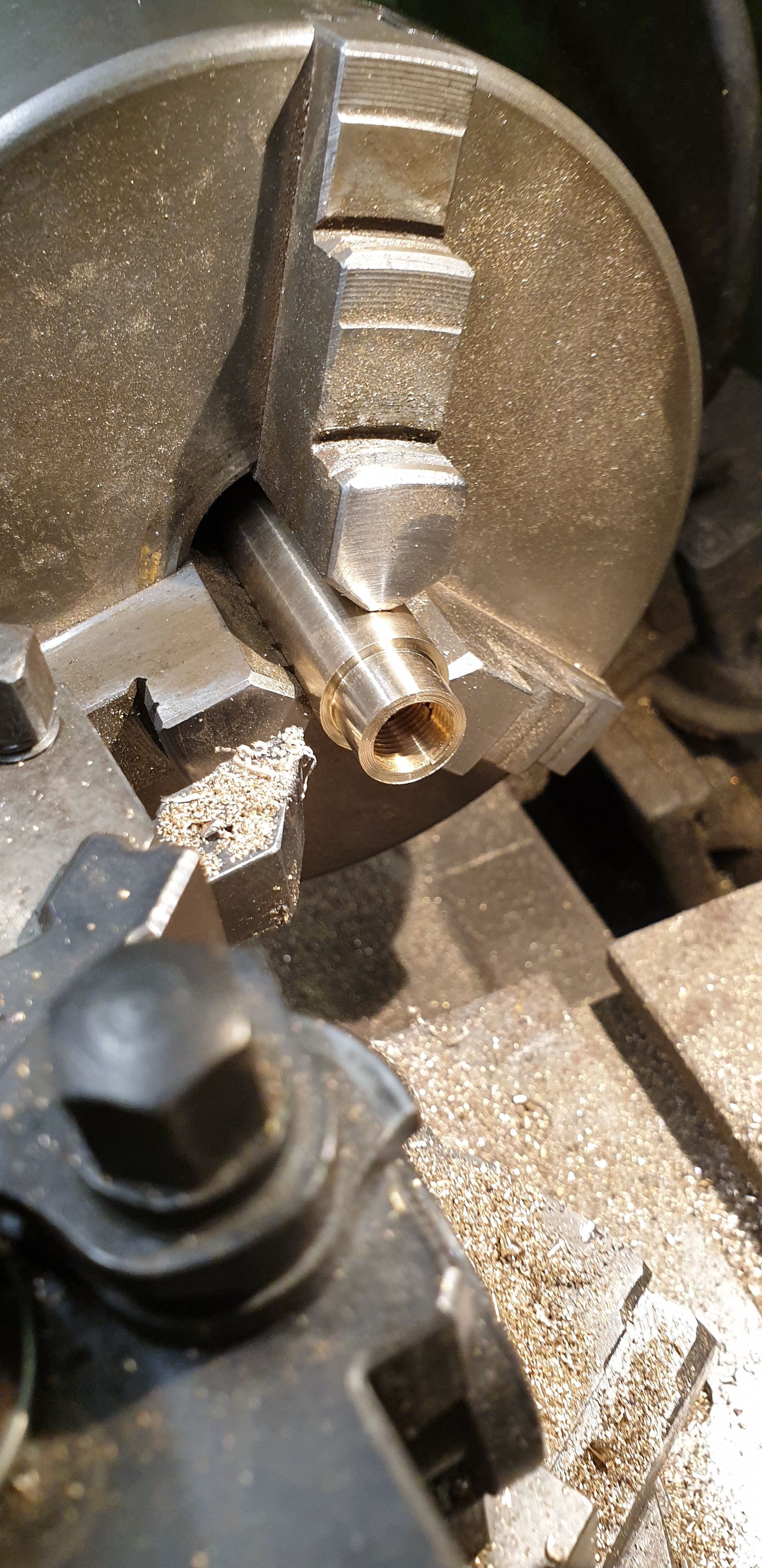
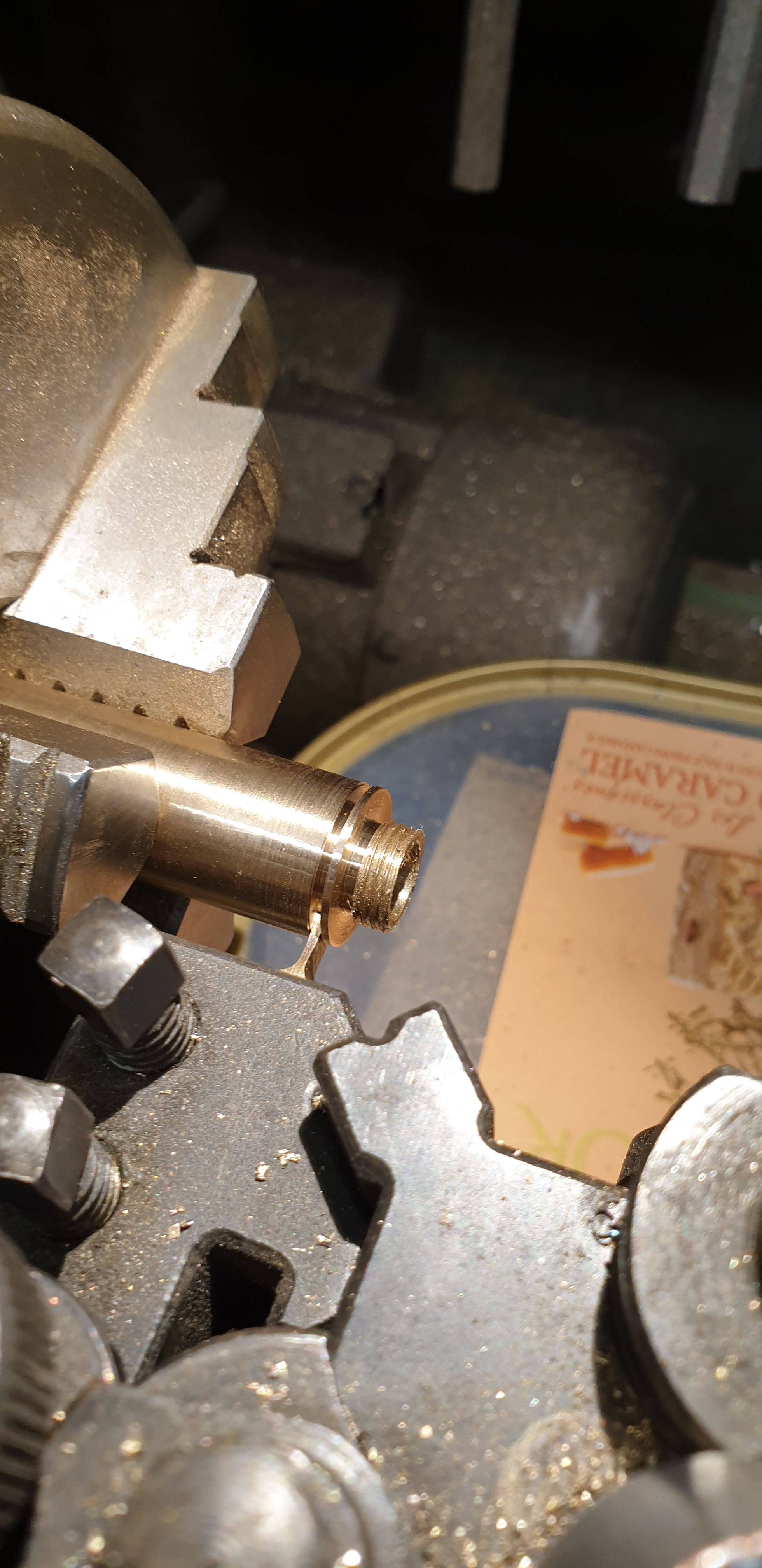
Talking of top hats, here's the first having had the inner thread machined/tapped, the spigot is 4.5mm long and has a small recess machined on the inside edge of the thread so it fully engages the bore.
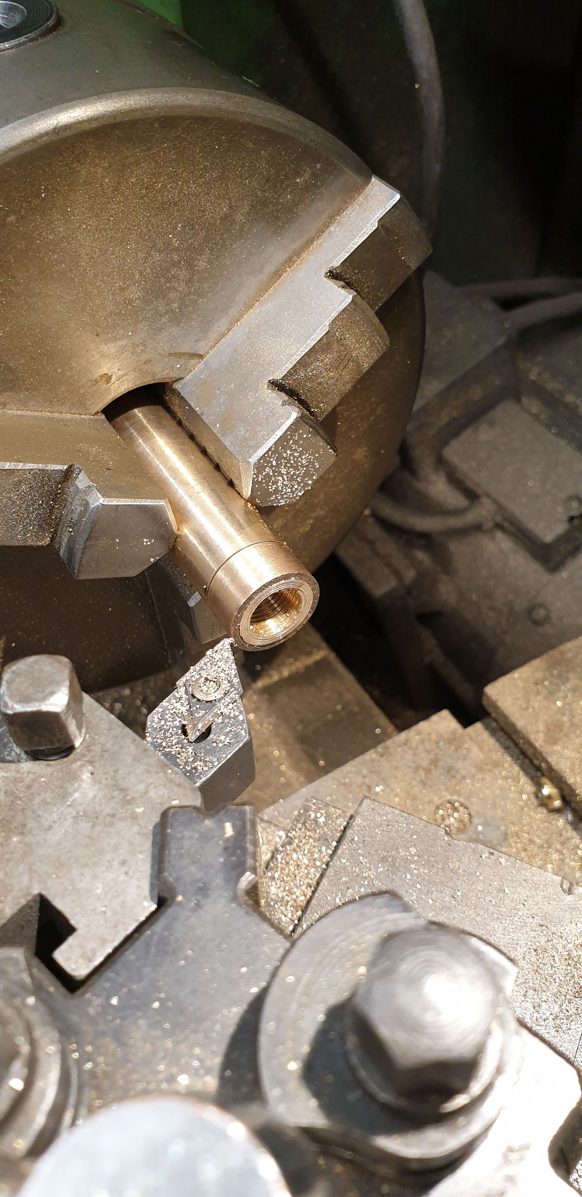
And here's the other side reversed in the 3 jaw and gently held to machine the face, note here that I have also machined a small chamfer. This is only done to the front top hats, this is for an idea that i have for the final stages, we'll see how that goes soon. The top hats and middle section ends will be angled more at the end for flow.
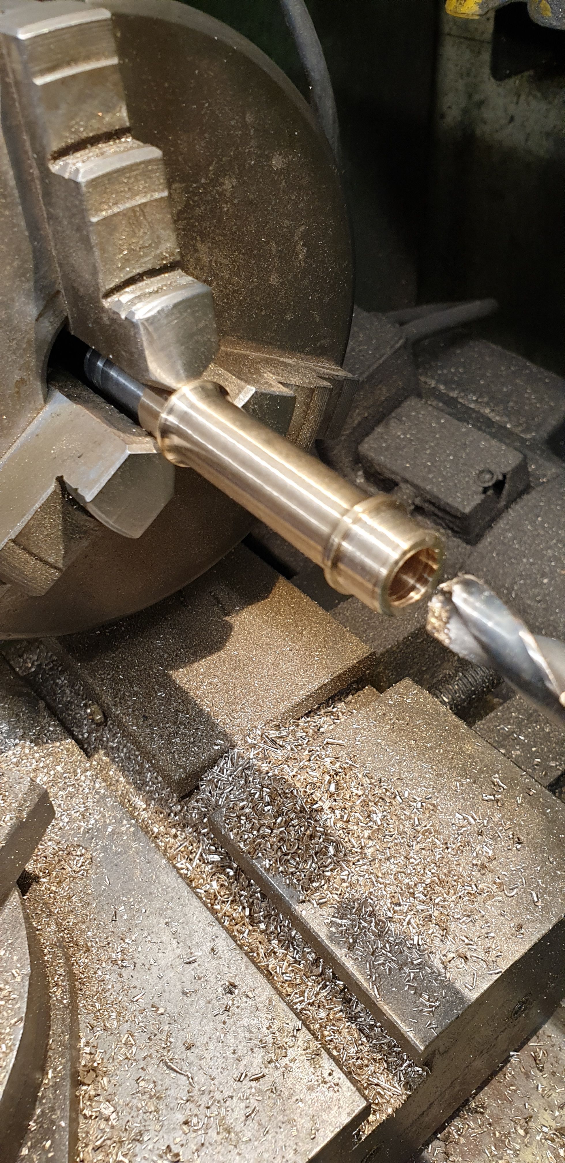
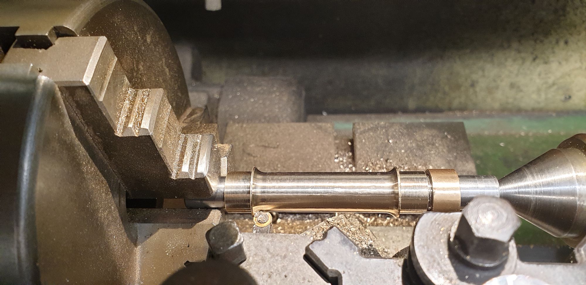
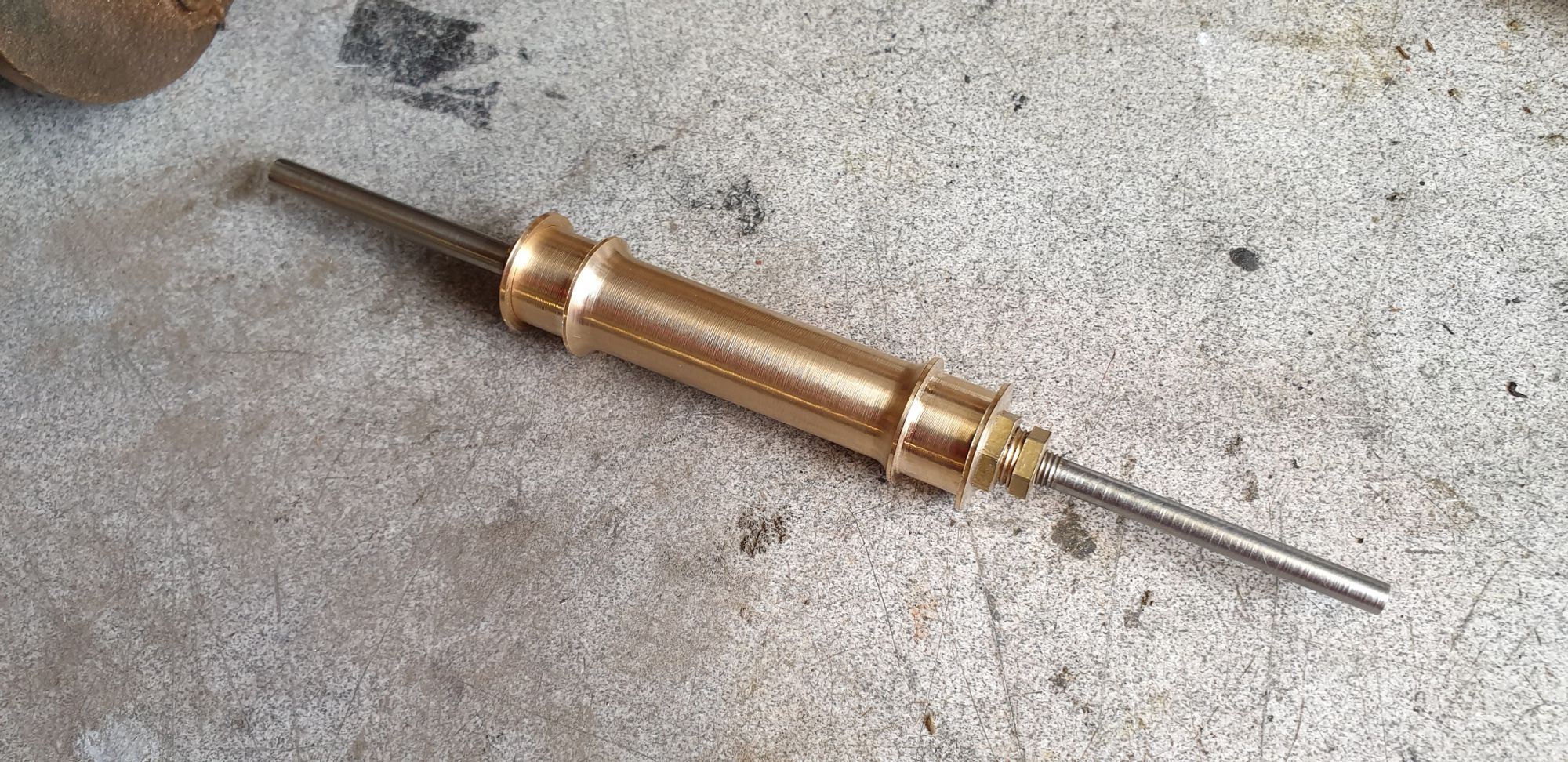
Ok, so after all that work I had 3 bobbin carrier's on their adjustable bolts and sitting on their spindle's, here's a picture of one of them awaiting the fluorosint rings.
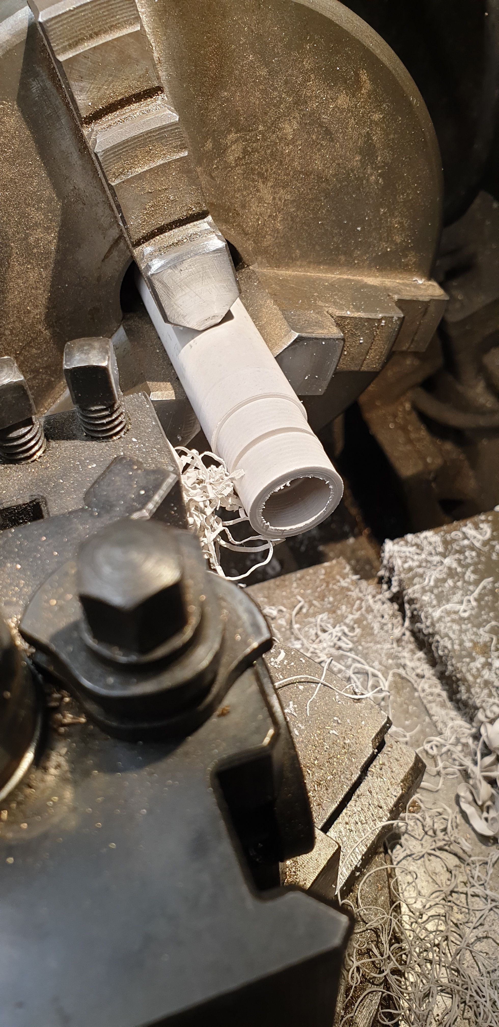
Now for the expensive bit, well at over £10 per inch Fluorosint certainly isn't cheap. This is the first time that I have used this material and i have to say that I'm impressed with it's machining qualities. Following normal PTFE practice I sharpened my thinnest tool steel tool using an oil stone, I spent a fair bit of time on this not knowing how well this material would machine, IMHO it's easier than PTFE, the swarf comes off in long strings of what feels like a latex material, that's the best way that I can describe it. I first turned down the OD on one end, reversed in the 3 jaw and did the rest of the 6" length to the same size so that it was all machined. Reason being that the material as cast is not a precision bar and moving it in the chuck for any reason would have changed its concentricity. Here we can see that the bar has been bored out to fit the journal, (they are tight fits) and the OD is being reduced to 11/16. I didn't machine this to size yet, I have left it slightly over and will do the final cut between centres as an assembled unit, I'll cover this in the next entry.
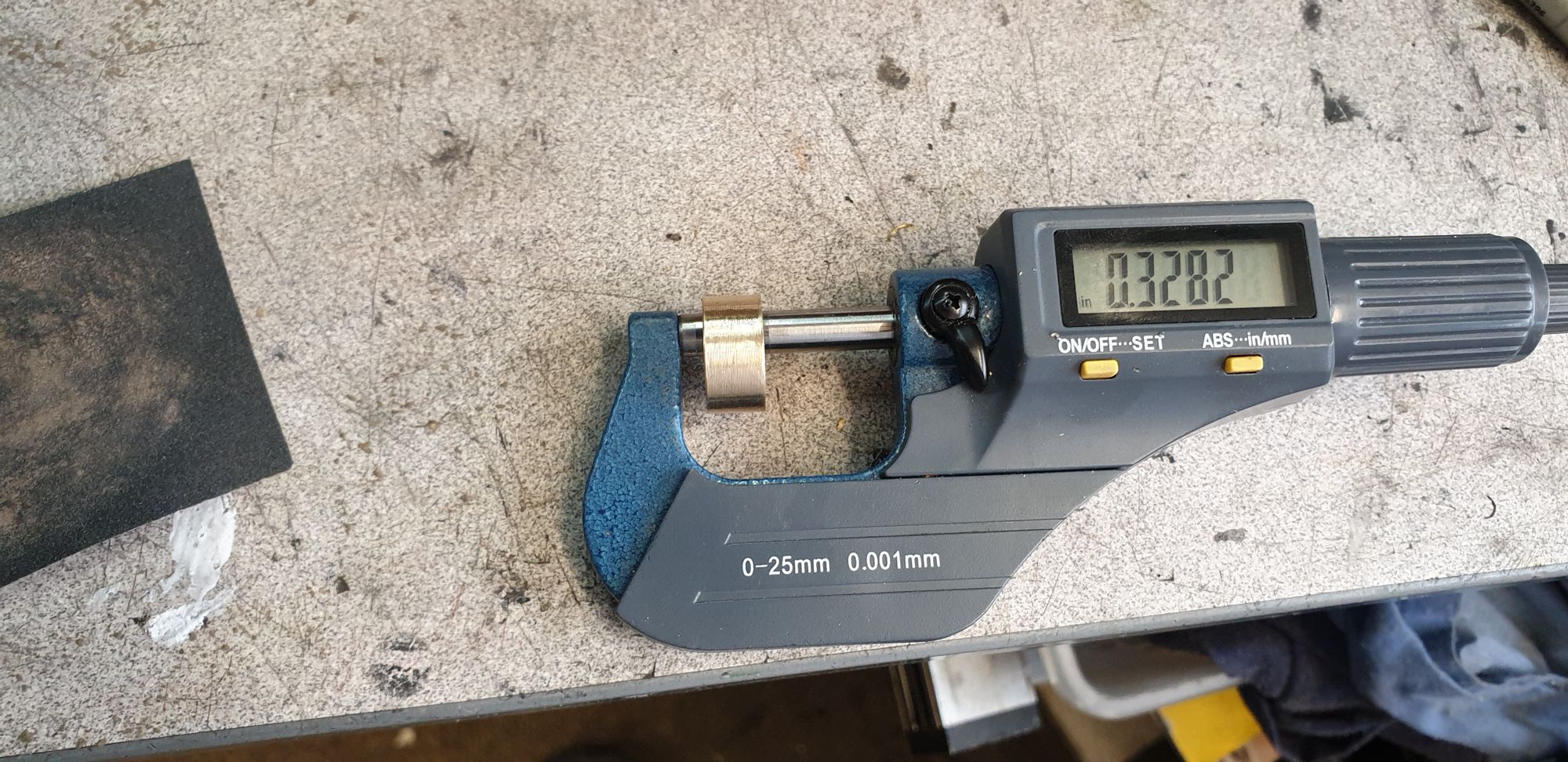
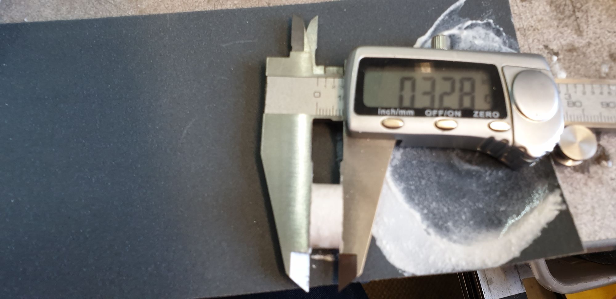
Once the bar was to size I parted off 6 pieces all overlength of the required 0.328 width. I then spent some time with W&D and carefully sanded each end until I reached the important 0.328. I was again very impressed with this material, this took no time at all, for anyone following suit, take it easy as you need little pressure to remove material from this stuff. It both cuts and sands like going through butter, not that you can sand butter of course but i think you get my drift..:)
Each bobbin with one top hat fitted was then held between centre's to further reduce the steps that hold the rings, this is why I machined a small chamfer into the 3 front top hats. You can also see here that I have drilled two holes in the top hats for a tool to grip, I have a few custom tools to make for this part to be covered later. I can machine these further still but will wait until the rings have been machined to size first. I also profiled the outside edge of the top hats for the same reason. The rear top hat was done separately.
The last picture for this entry shows the 3 valves all machined, just leaving the final cut of the Fluorosint which I'll do next week. I have taken one apart to show the various components involved. The plan is to clock each assembled unit on the lathe and take the final cut, when all three will be cut at the same setting. Also in the picture is the simple tool that I made to measure the port outer edges. Before I permanently fitted the middle cylinder one of the things that I checked was that I could get this tool in to measure the ports.

Next entry once the bobbins have had their final cut to size will probably involve the finishing touches to the outside cylinders, once those are done (including the cladding) I think that I can mount these to the frames for the final time. The valves can be set easily the same way that I believe the full size loco is. For the outside cylinders this requires the front curved running board section to be off and the front valve guide covers removed and for the middle cylinder that rear cover is taken off (no valve guide here) which is handy as it means when the 2:1 lever is fitted it's not going to need removing to adjust the valves. Lot's still to do but I'm getting there...:)