

I have left the final fitting of the valves until the connecting rods, crossheads and bearings have been made and before they can be fitted the cylinders and the slide bars need to be fitted to the frames. Therefore this entry will cover the work involved to get the cylinders ready for fitting, it was at this stage that I realised that the draincocks also need to be made and fitted along with their linkage, the work load seems to increase on this model with each new step taken.
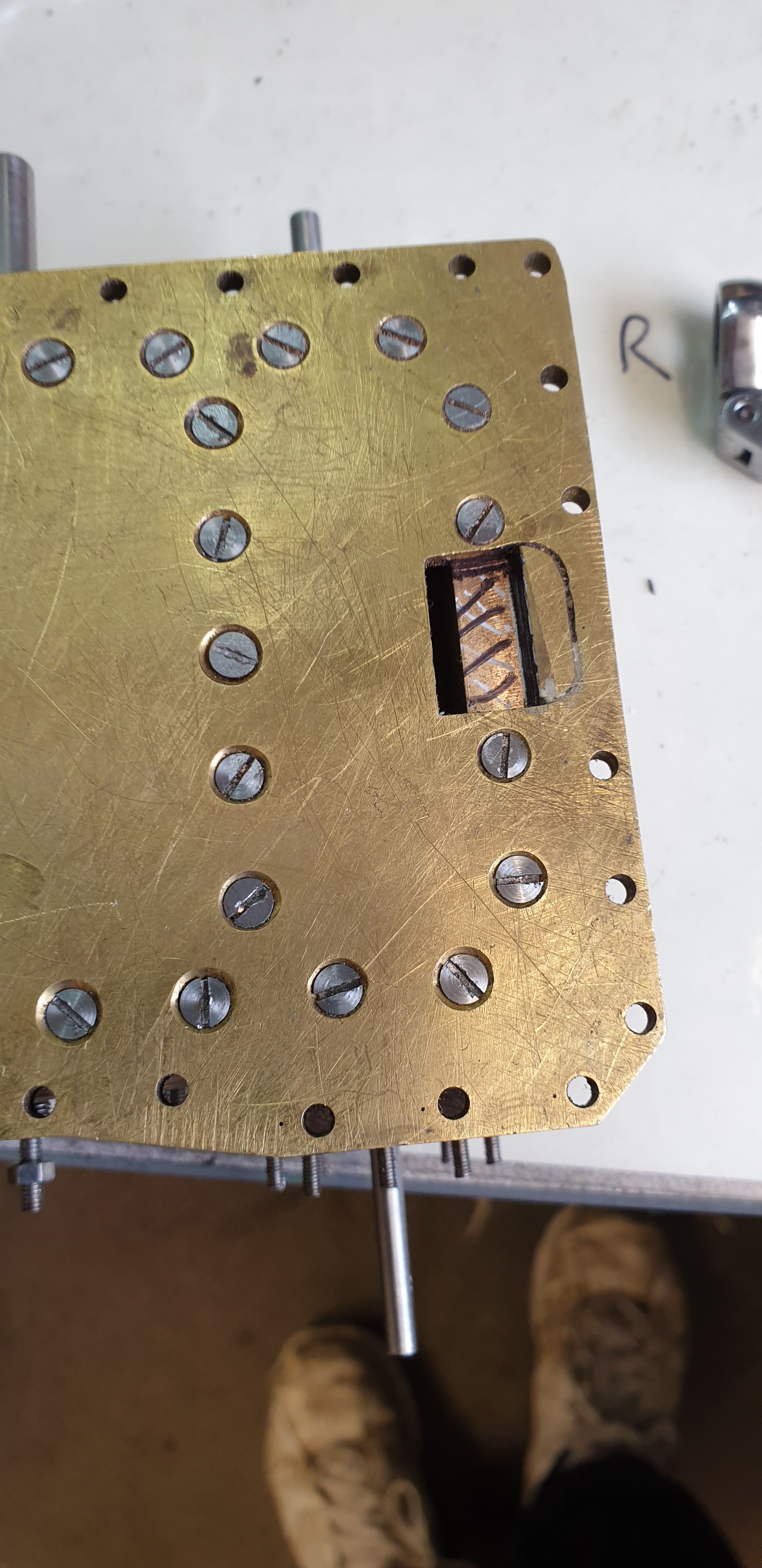
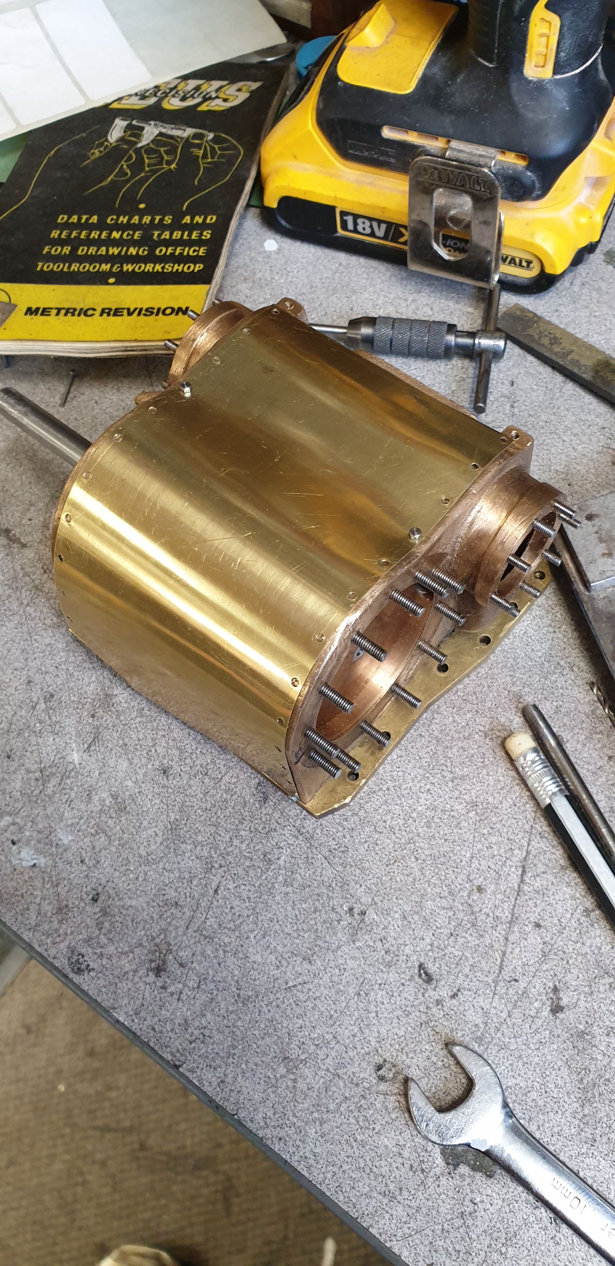
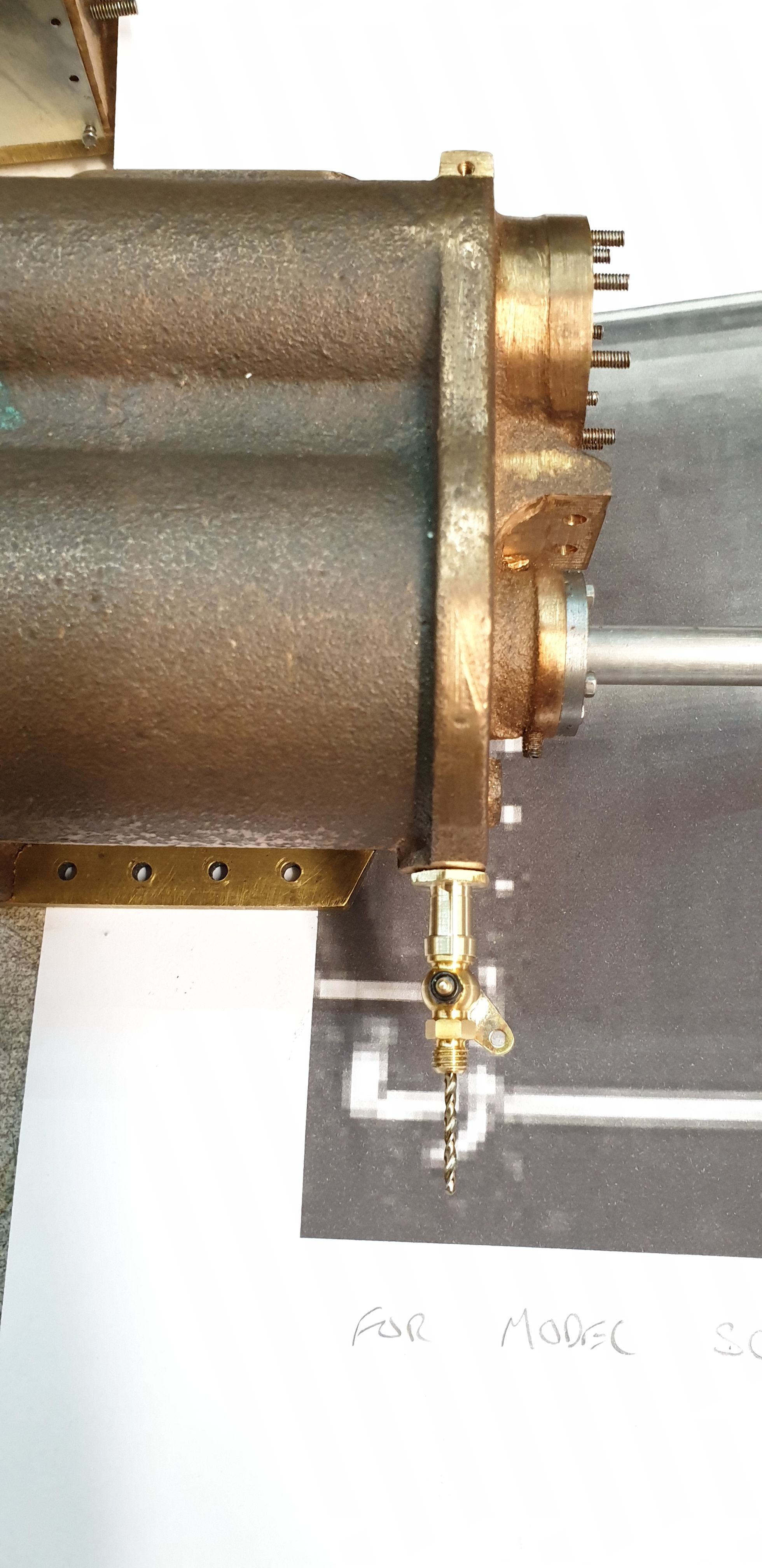
Ok, so before any of that can be done, the first job was to finish off the exhaust passageway from the cylinder through the flange and into the saddle. This is just one of those many jobs left outstanding during the build. The exhaust is directed up from the outside cylinders into the saddle and thus to obtain good flow the cut outs through the flange needed to be angled, approx 45 degrees. The cut outs in the frames were angled long ago but I still needed to remove some metal from the cylinders themselves. The first picture shows the area that needs working on.
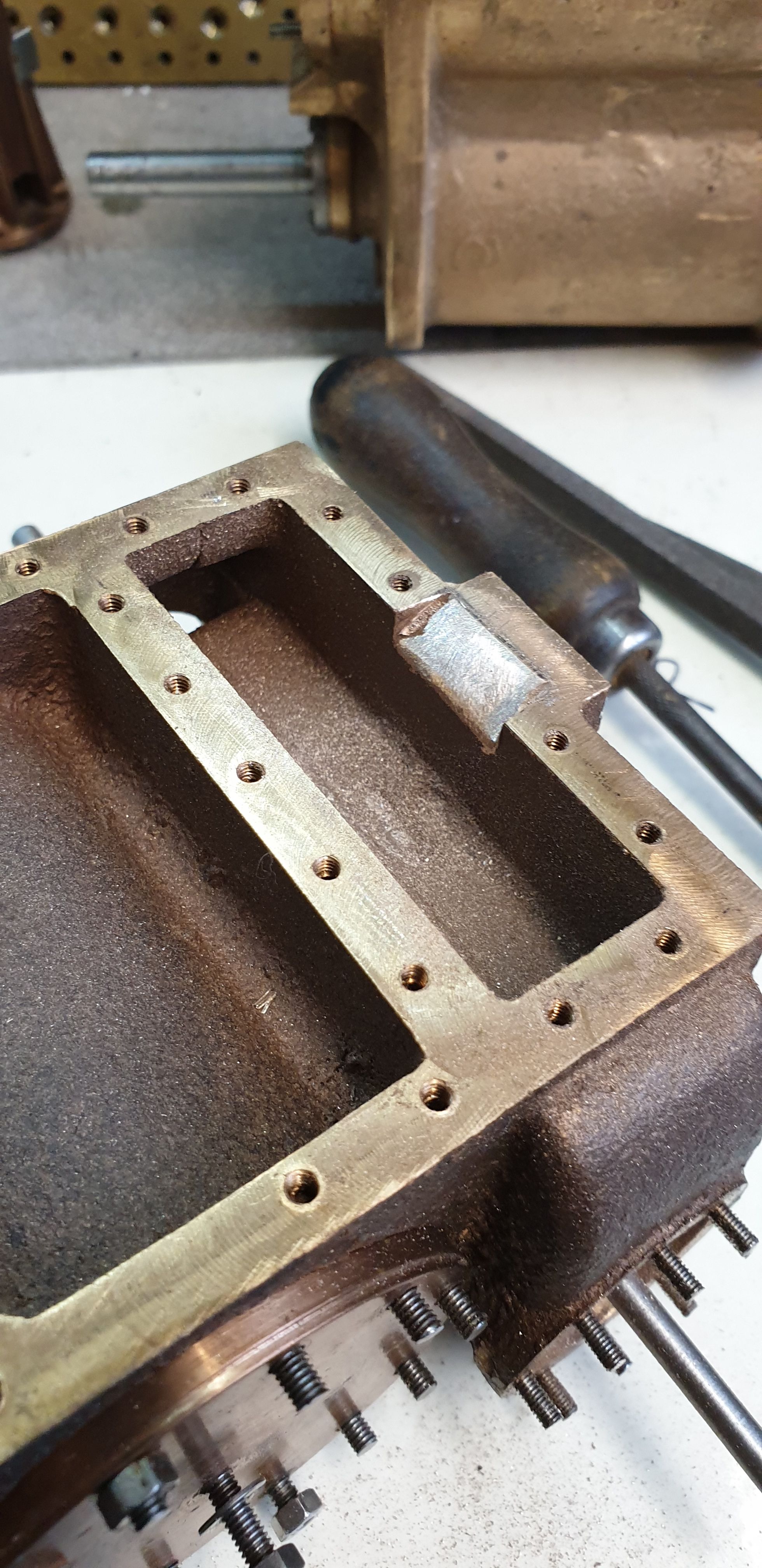
with the area that needed removing marked out I then removed the flange and ground/filed away the section involved. You can see the angle/area involved in this picture.
For those who may be asking why the filed area isn't central, if you cast your mind back some years I repositioned the smokebox back 1/8 " further than drawn to match photo's and GA.
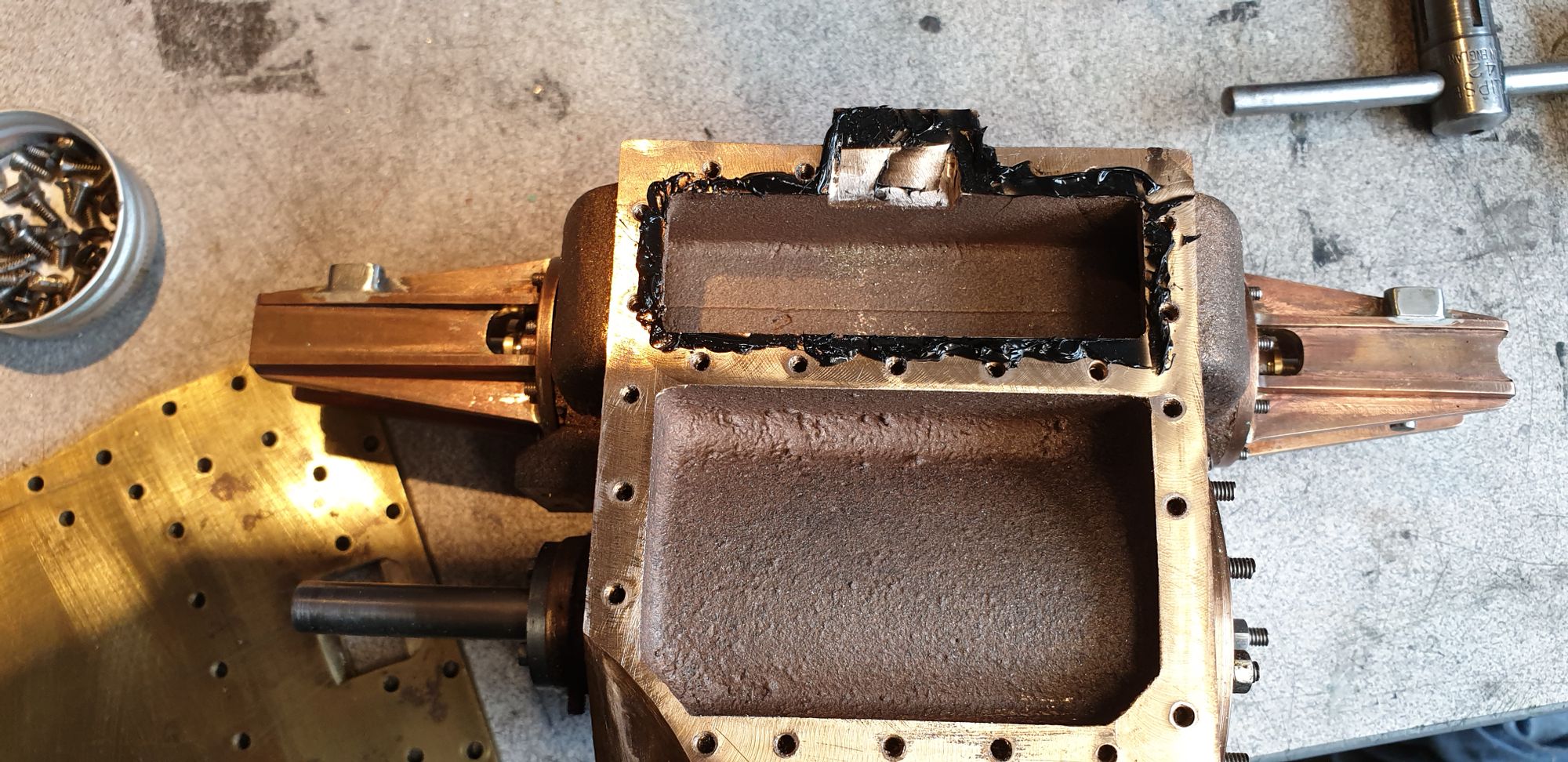
Before refitting the flange for the last time I sealed the area around the exhaust with high temp silicone, I'll use the same when fitting cylinders to frames and also when the saddle is fitted for the last time.
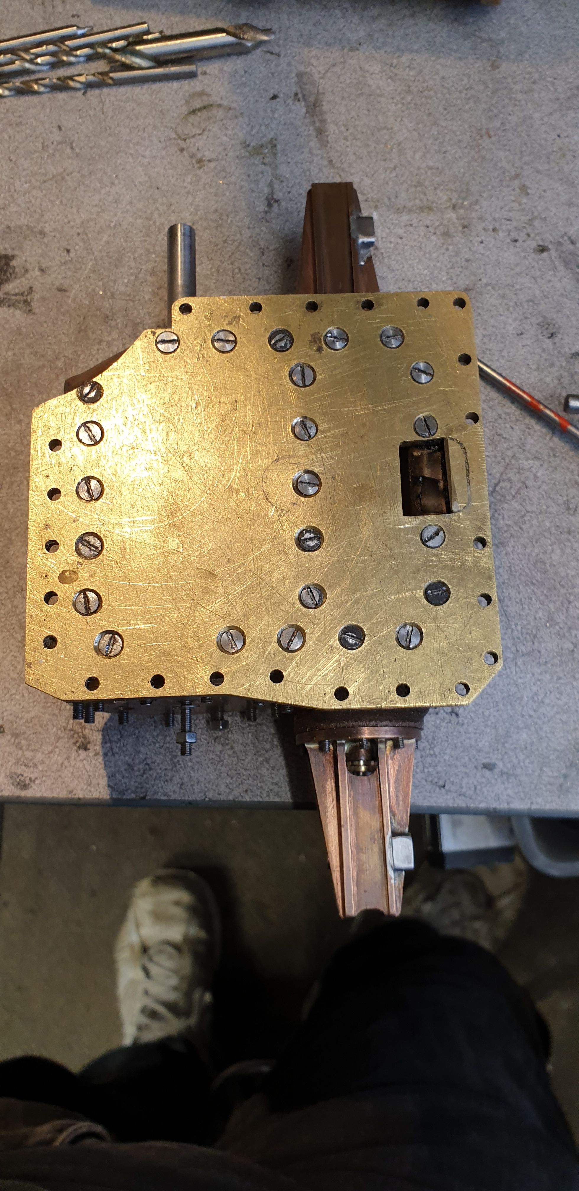
And here we have the flange back on its cylinder...
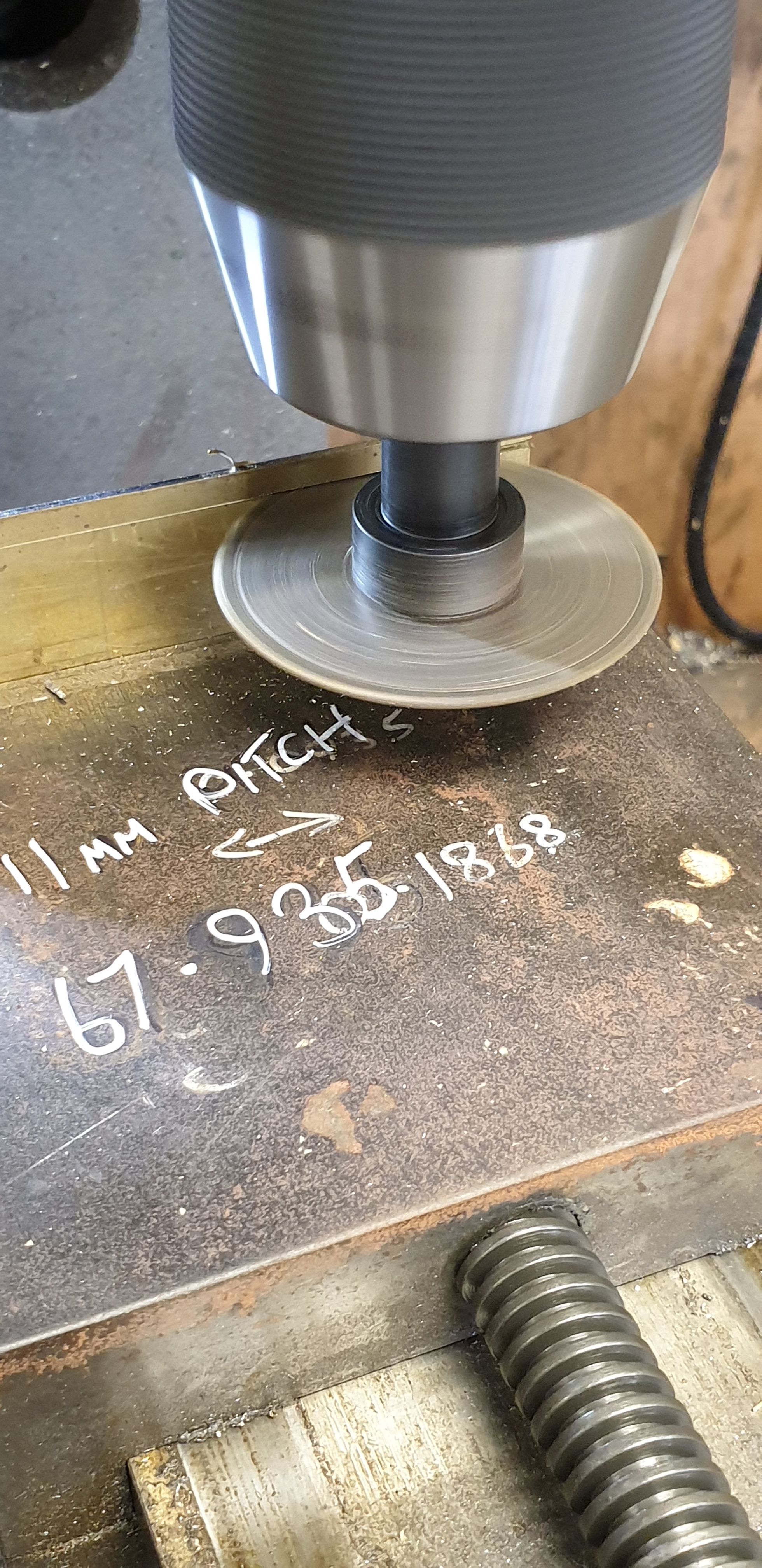
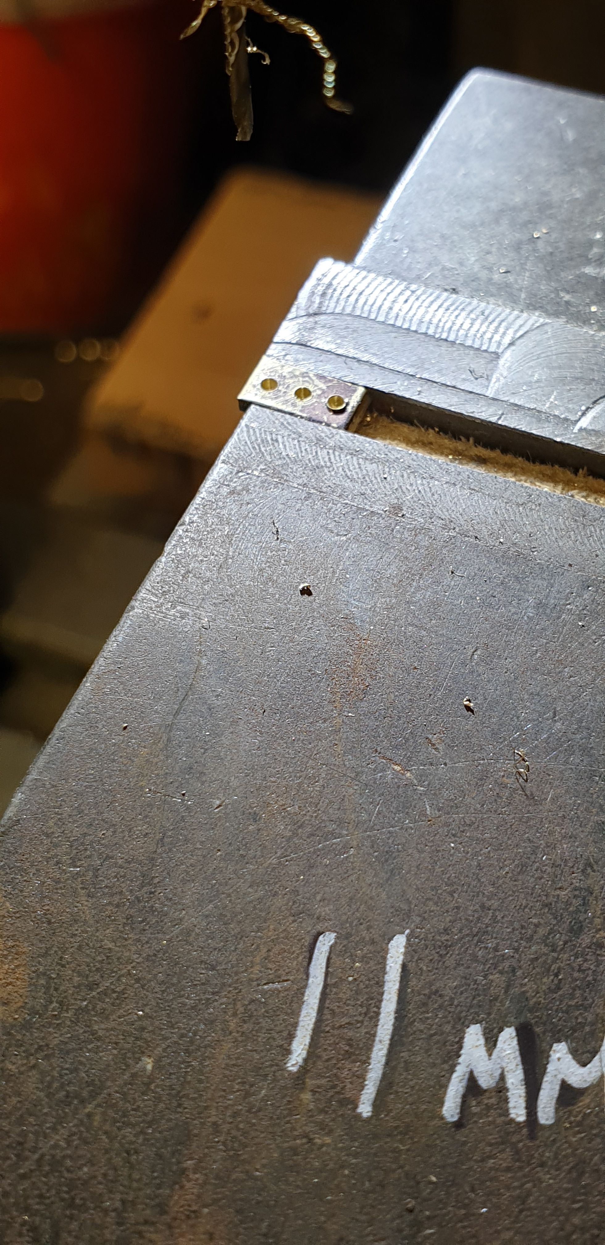
Now I'll put this picture next as that was the order that I did things but this has now changed. Nothing wrong with the fitting, it's just that once I had got this far I decided that using 10 thou brass for the cladding may not be the best of ideas. There are plenty of photos of the full size with big dents in its cladding, problem is it would not look at all good on a model and this fine brass will dent very easily. I therefore have changed the brass for 13 thou tin which is much tougher, I'm come back to this in a later entry, for now I'll just show how things were looking. BTW the pitch between the 10 BA bolts is 11 mm, I scaled this off some photos trying to have the bolts in the same position as full size. I did note from photos that there seems to be a bolt more or less centre to both the valve spindle and main piston rod and thus these and the total number were my main aim when working out the pitch.
I then paid attention to the draincocks and here i learnt something, many thanks to those who helped me here. I wasn't aware of what has turned out to be relief valves fitted to the draincocks, interestingly, these were kept even when cica mid 30's the cylinder cover relief valves were fitted. So for all of 4472's career she had draincock relief valves and from mid 30's she had both types of relief valves, well into preservation days.
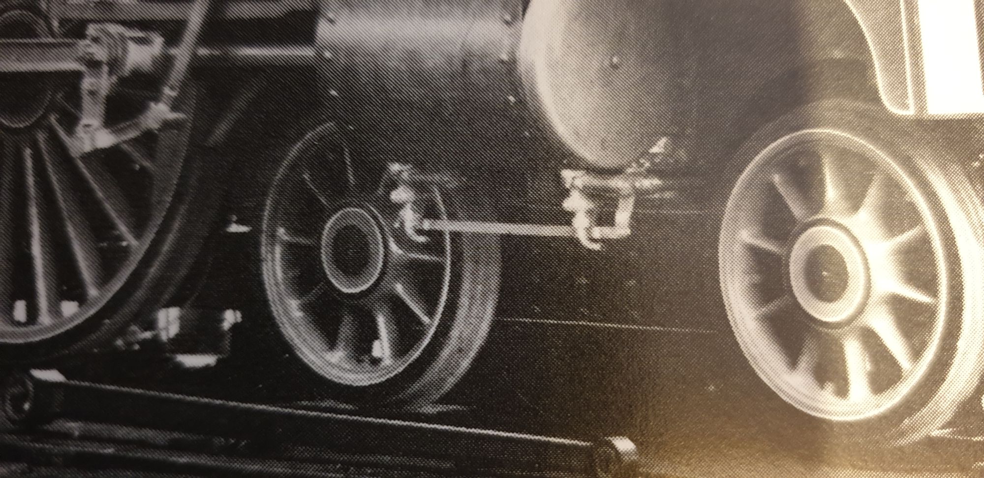
I have a couple of pictures to explain what is there, here is 1470 when built, these are very much like 4472's, I won't swear that they are the same but they look very much like it. One thing that I have noticed during my research since first discovering the draincock relief valves is that the exit pipes all seem to vary in height and shape. For my chosen era of 1938 they are simple curved elbows as seen in this picture, however from what I can see, 4472's pipes sat lower, more or less inline with the bogie axle centre. AS you can see, 1470's sit much higher and in fact look smaller OD too. Here's 1470. It took me a while to work out what was going on here, the relief valves confusing matters but I then realised that Don's drawing for the draincock linkage follows what can be seen here exactly. It's a bit involved as all 3 cylinders are linked and will have to wait for a while to explain but once I get onto the linkage in a later entry it will become much clearer.
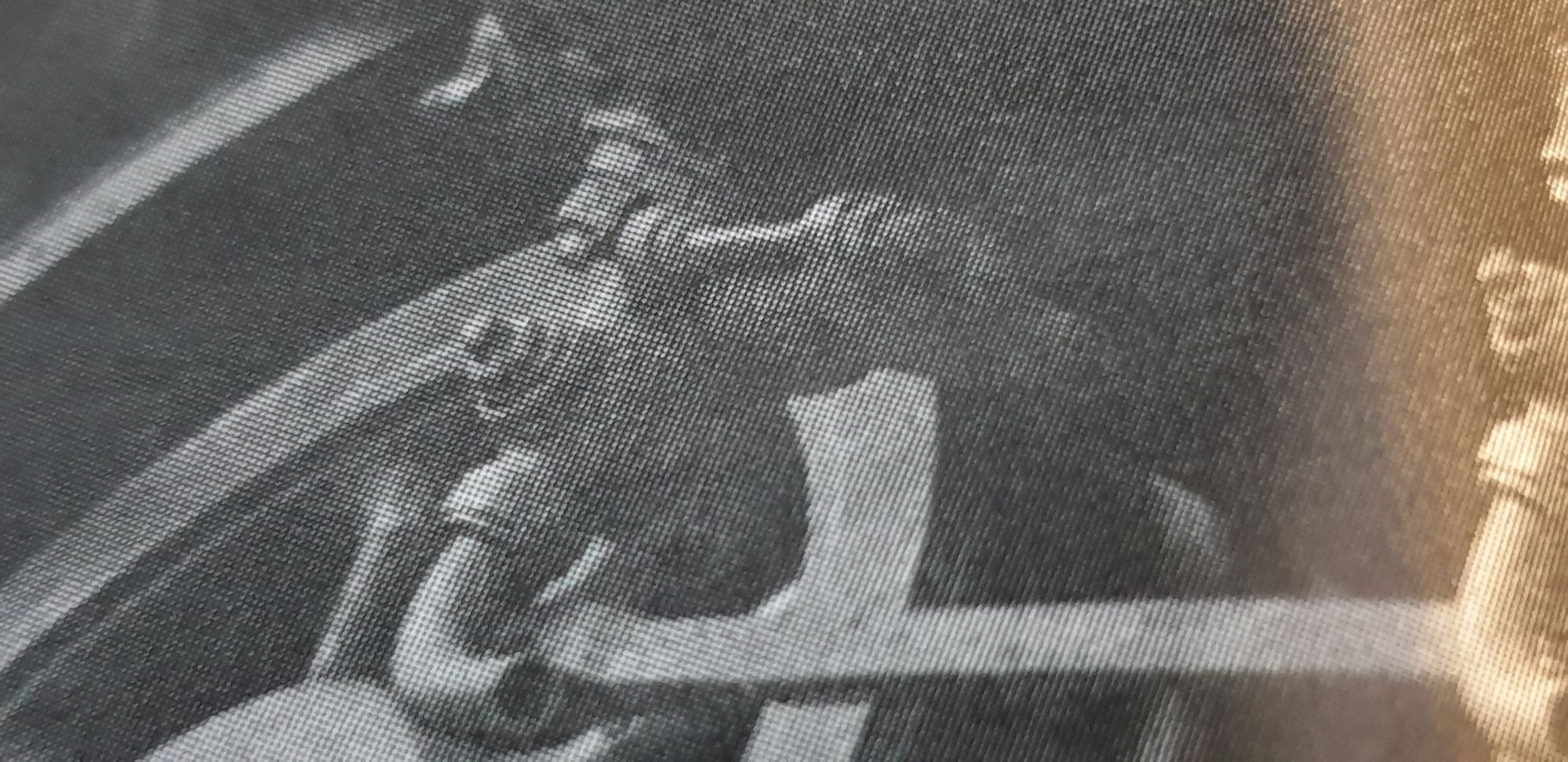
I was lucky to have this image, it's not 4472 but is a pacific and the picture was taken around my era so I will use this for the fine detail of the relief valve/draincock assembly.
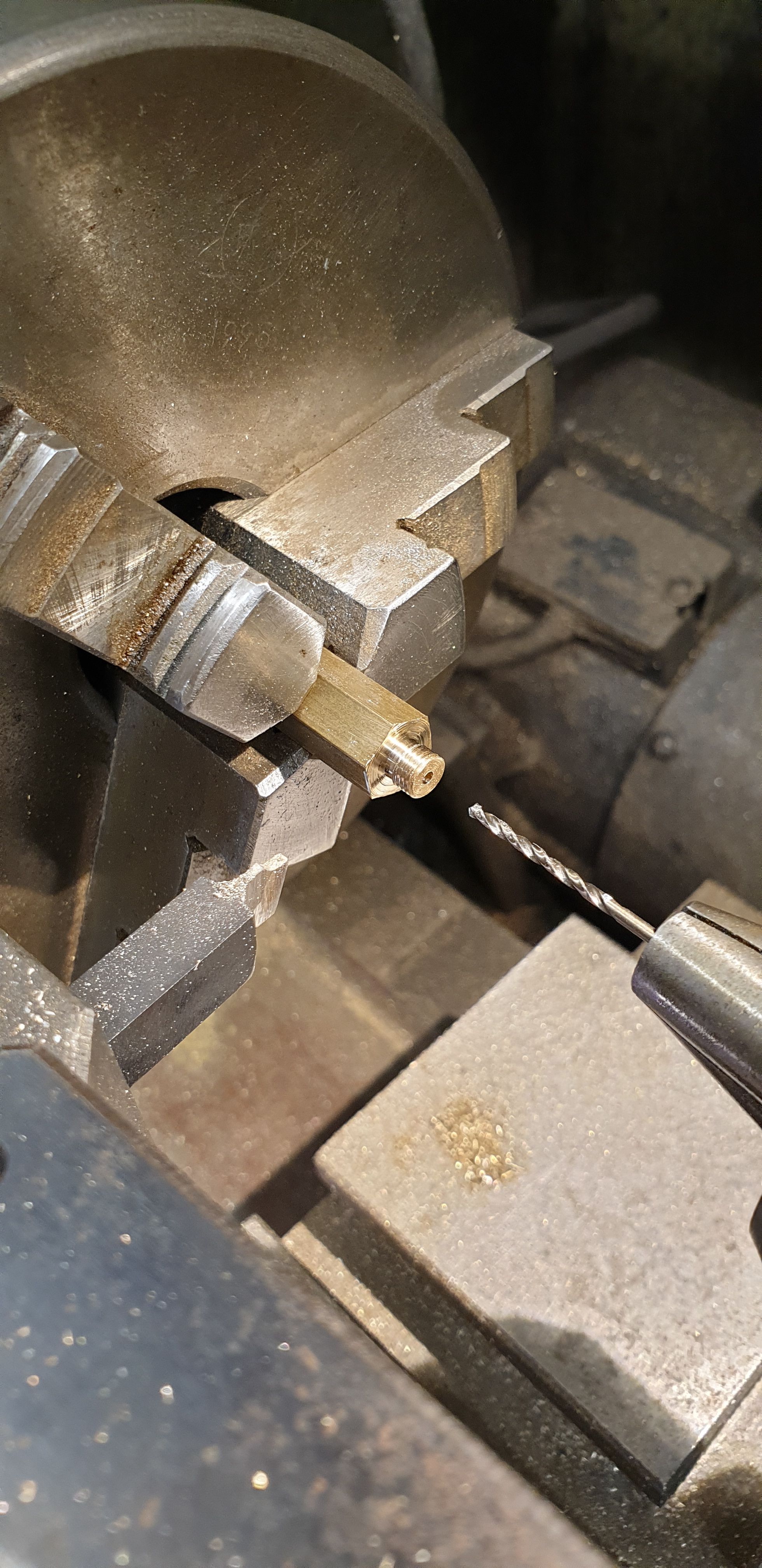
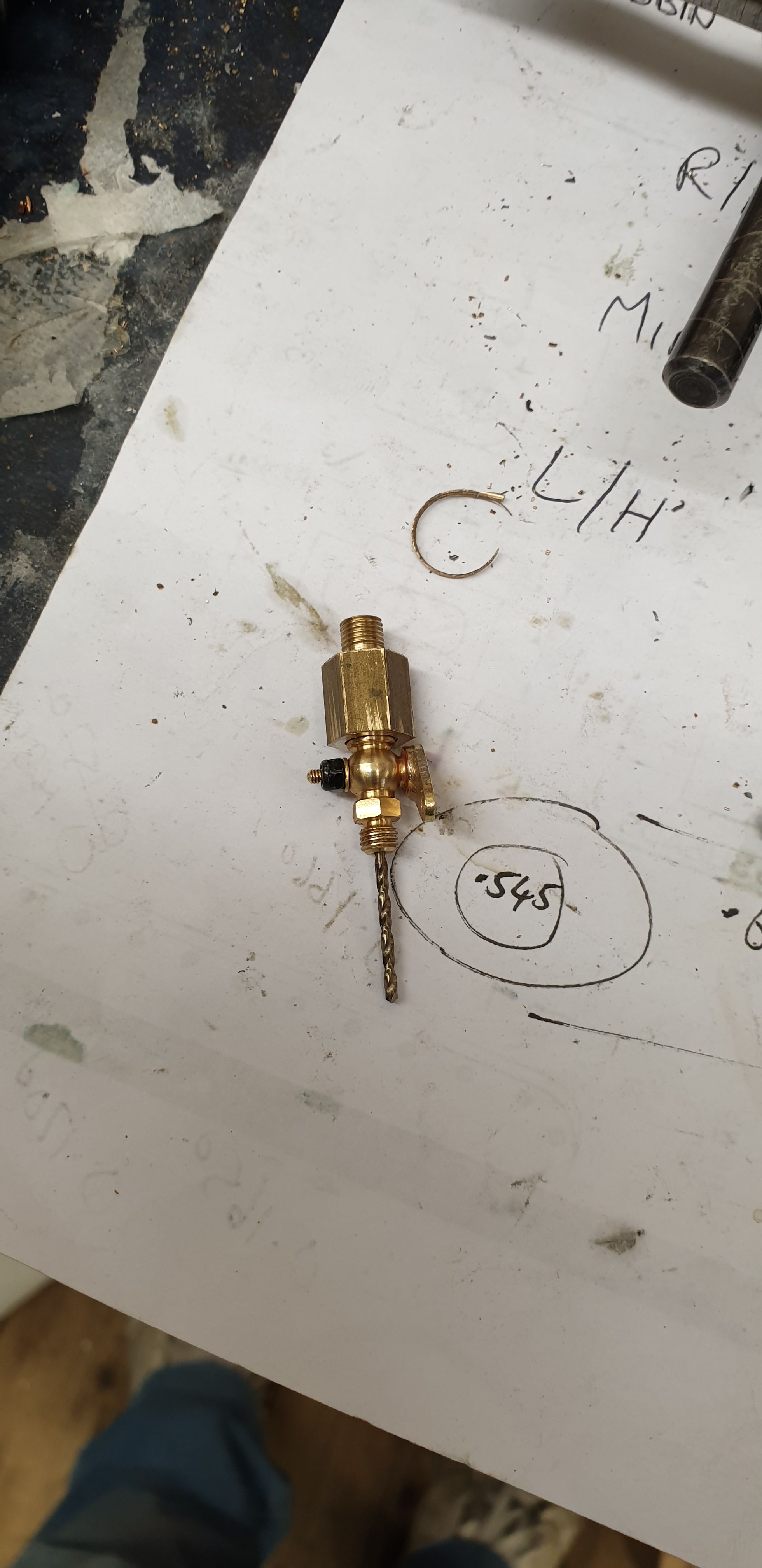
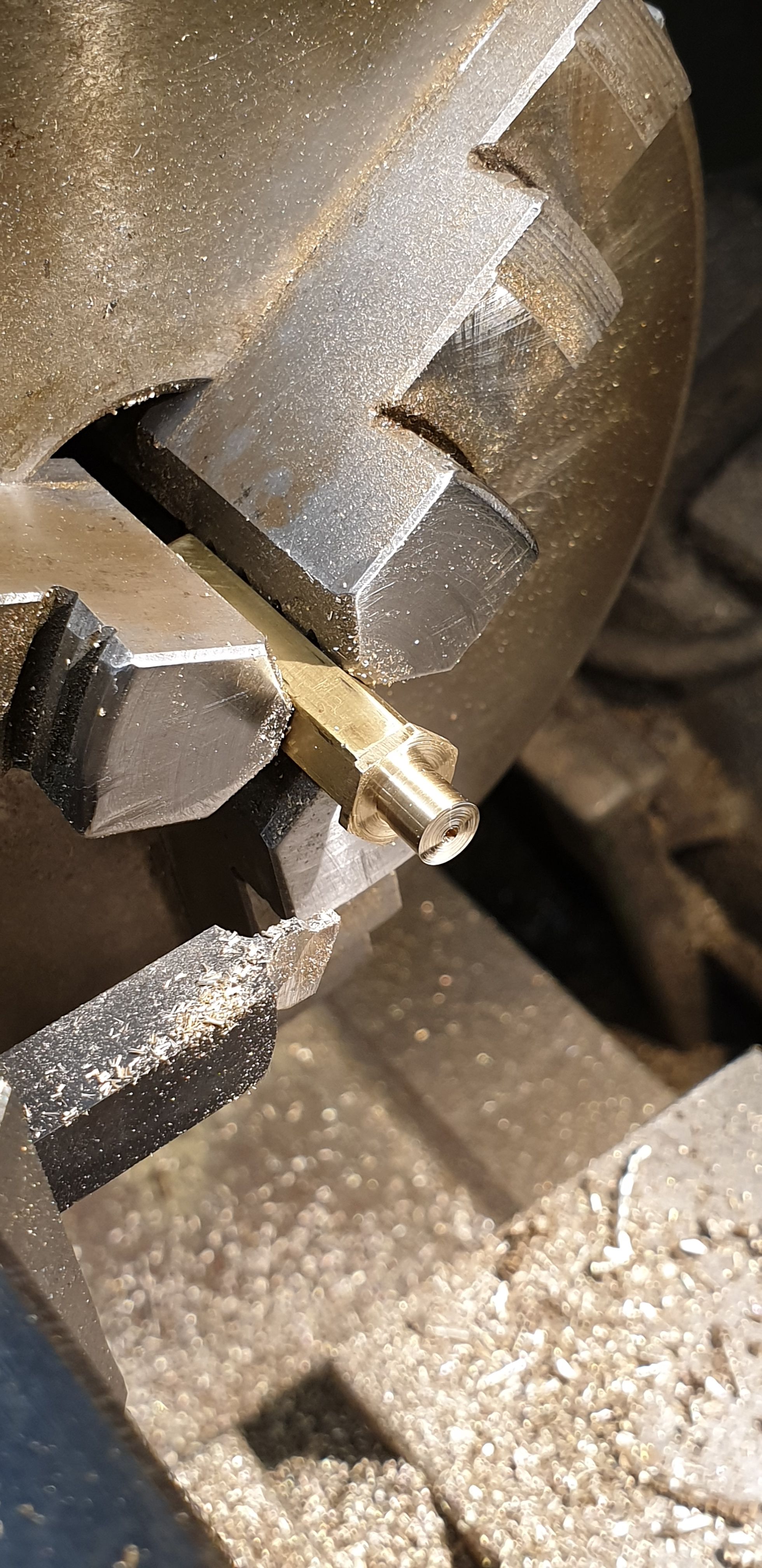
Now that I had some idea of what was going on I made a start on the relief valve body, this changed a number of times during fabrication as more info became available. I chose to use 3/8 brass hex bar as the basis for the body, the first job was to turn a small spigot for the thread required to fit the cylinder. Confession time, I discovered or perhaps had just plain forgot that when making the cylinders one of them I wasn't happy with the thread for the draincock mounts. I'm not sure what happened but suspect (can't remember) that when drilling the taping hole that I picked up the wrong size drill bit. The thread still cut but I wasn't happy with the fit and thus opened up the offending cylinder to 7/32 from 3/16. As it happens, with the addition of the relief valve body this was a simple case of just threading two at 3/16 and the other 2 at 7/32, I'm not going to fit the reliefe valves to the middle cylinder, I have enough work to do as it is and since these valves are dummies saw no point, i'm not that mad...:) Picture shows the first body having had the spigot turned and threaded and also that it's had a 1/16th hole drilled through it, this matches the hole size in the draincocks, BTW I have decided to use commercial draincocks, the ones that I have chosen are from Polly Engineering, as we progress you'll see that these are more or less the same as those fitted to the prototype.
Here we can see a relief valve body blank temporarily connected to one of the 3/16 x 40 draincocks
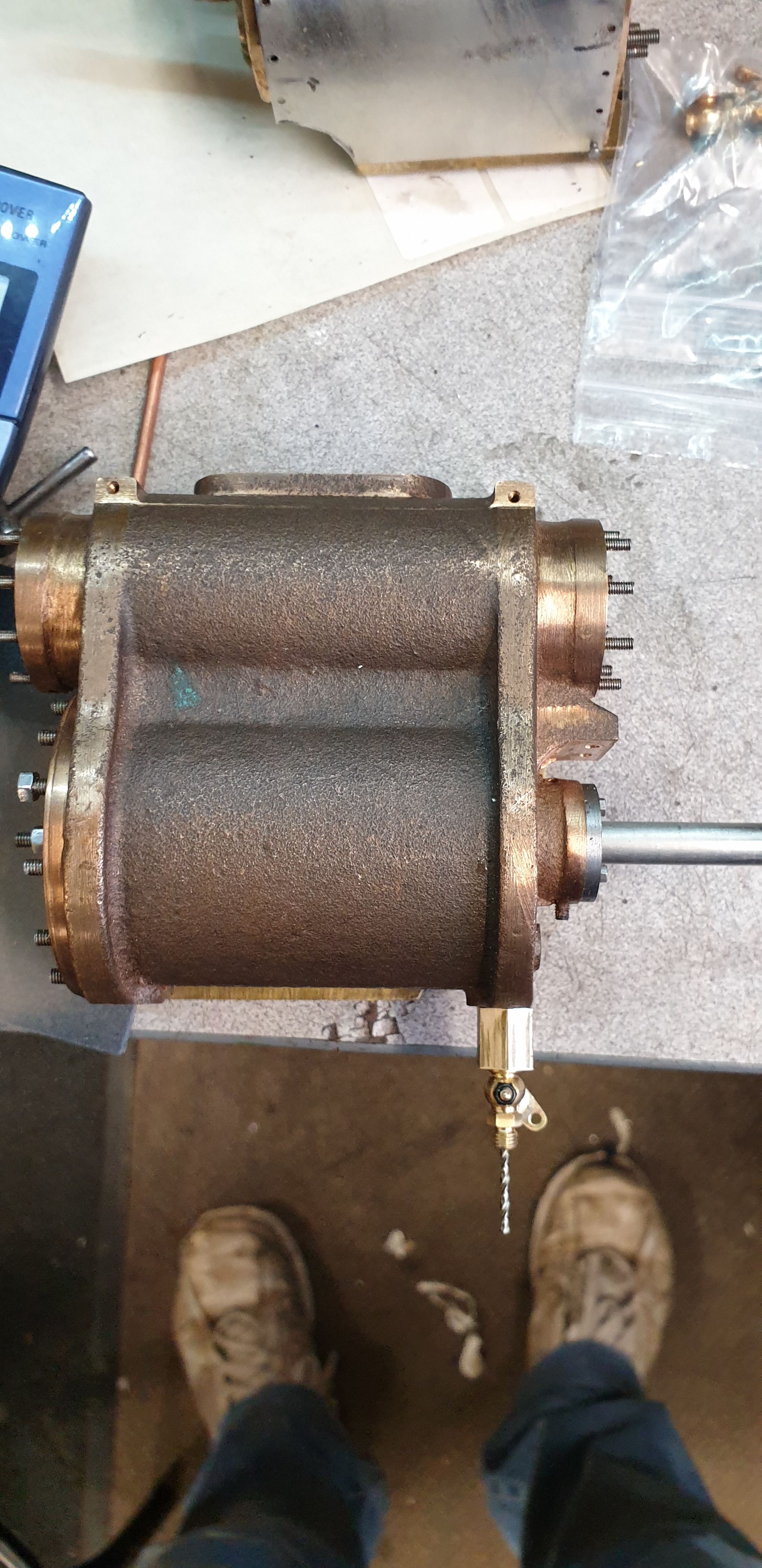
And tested on the cylinder for overall size.
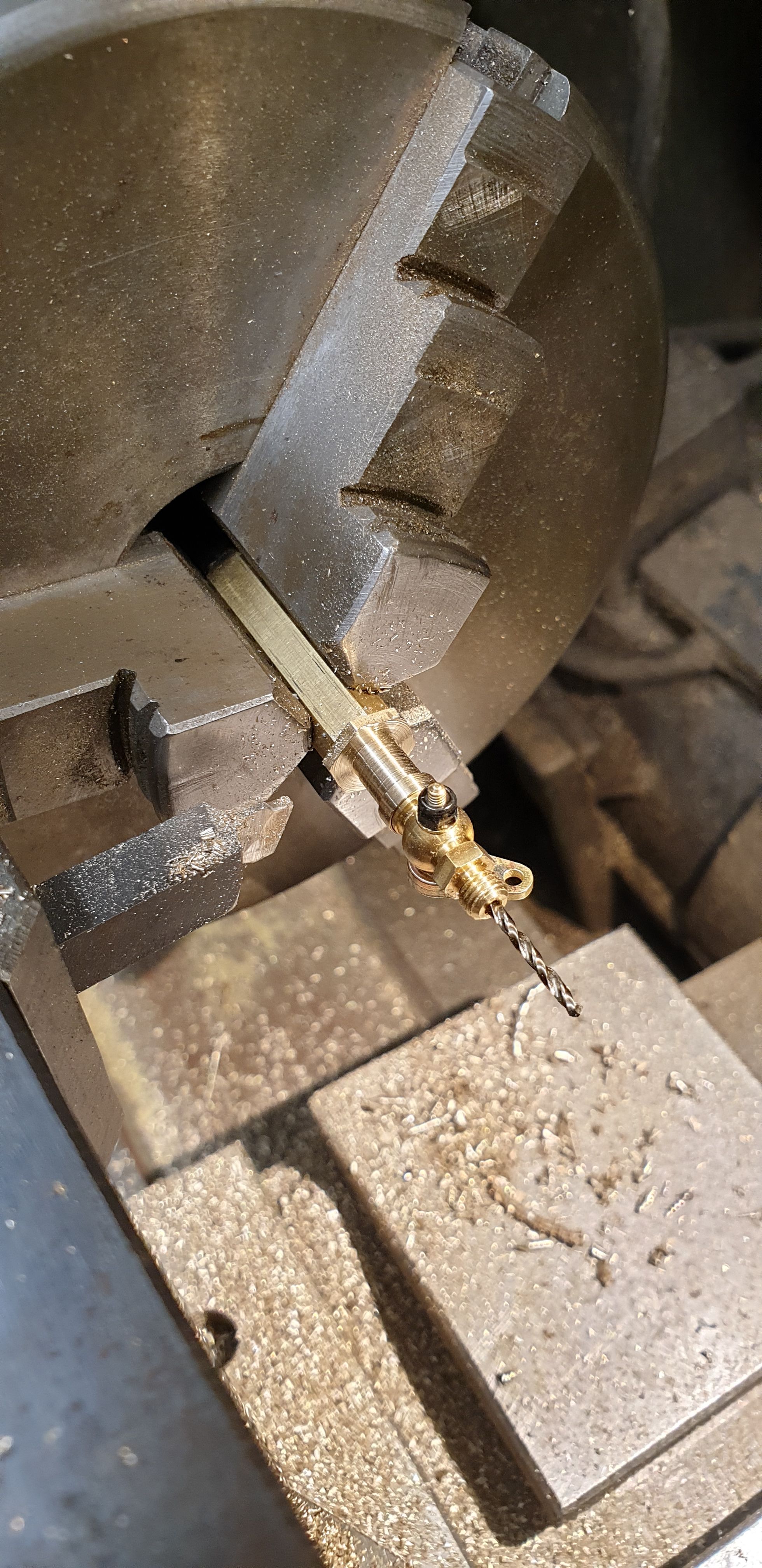
I then begun machining the blank down to something that looked like the profile I could see on the 1924 PR photo of 4472(then 1472)
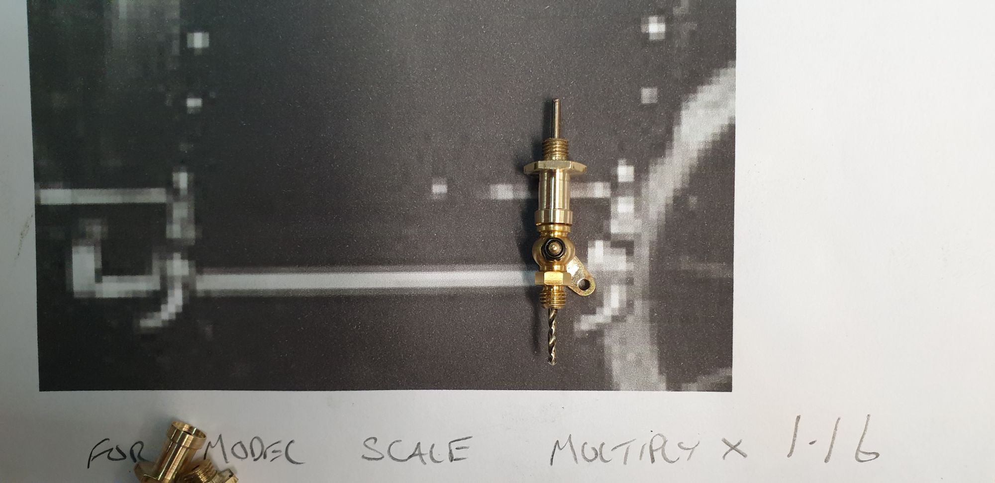
Here I have laid the parts over a blown up image of the 1924 photo, the photo worked out at 1:16 scale
And here is what it looked like on a cylinder..
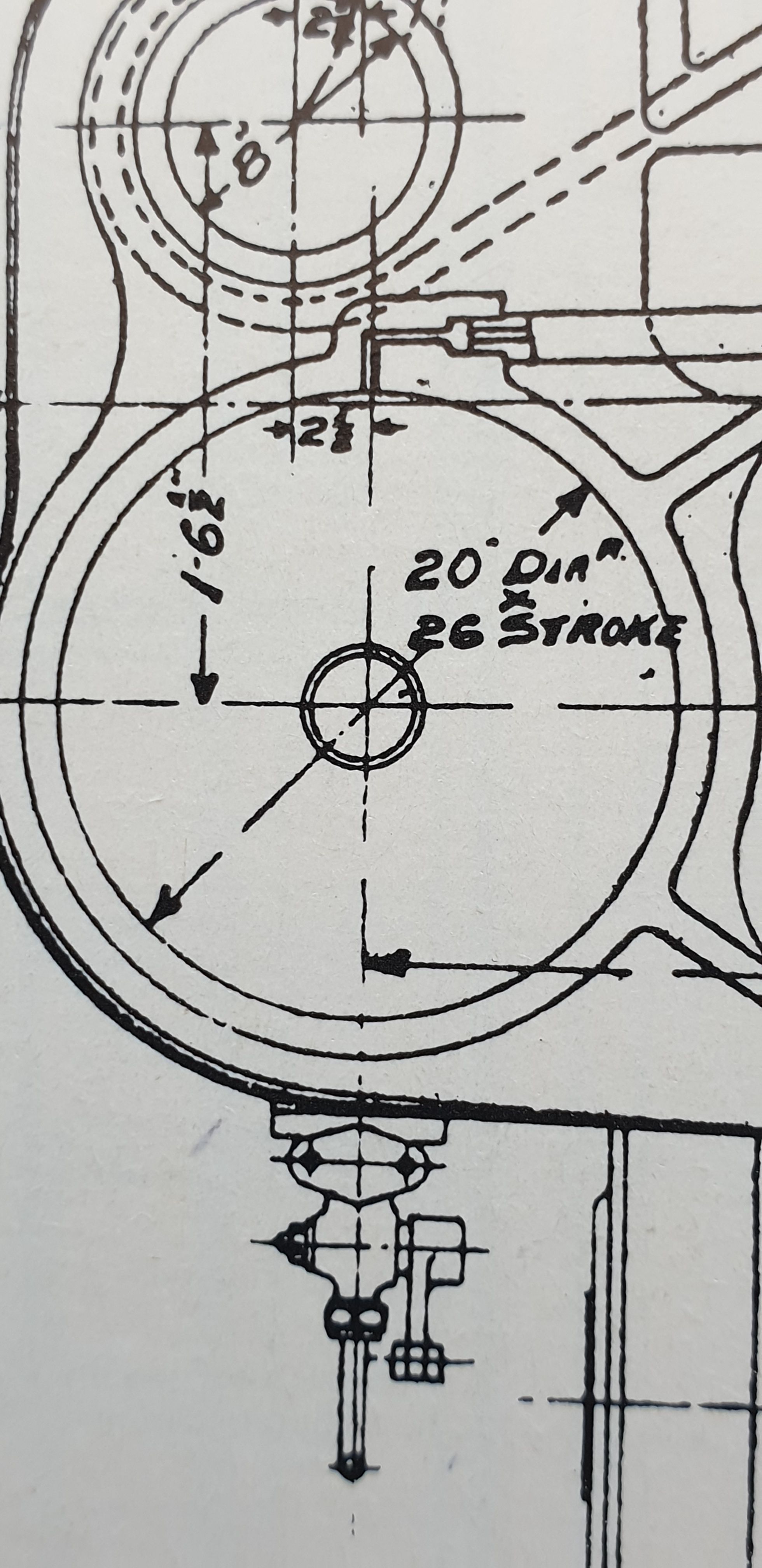
It was at this stage that things began to get a little clearer on the part that I was trying to make and I'd like to thank those who sent drawings/pictures to help. As mentioned I have a fairly large collection of books/photo's on the class now and while browsing through some of them I came across this drawing in 'The Gresley Pacific's' by OS Nock, this changed everything. I now had a head on drawing that I could scale from and after working out the scale at 4.71 I took some notes and wrote up some dimensions.
Now armed with a drawing that I could scale from I then took another look at the valve bodies and reduced their height and removed the small step I had included in doing so. The good news is that the Polly draincocks not only look like the prototype but are more or less the same size too. This picture is just included to show how I have changed the body, i will probably remove a little more still but will make up the valve plates first to see how they look when placed next to the body and draincock.
I have made a start on the end plates, here I have cut down some brass sheet using a slit saw, this saw will probably be used a number of times for the draincocks and linkage. The strip is less than 4 mm wide.
I then cut up the strip into 8 x 7 mm sections and drilled them ready for the spacers etc. Spacings are 2.2 mm, the central spacer will have a small spring over it when assembled, I have ordered some miniature 2.2 mm OD springs to fit over the middle spacer ( not really a spacer but hopefully shows the middle bar that I'm talking off) for this job, this is very much a case of make it up as I go along, hopefully it will all work out in the end.
that's it for this entry, I'm going to be very busy getting these cylinders ready to be fitted for the last time. On top of what you see going on here I also need to get them in paint and make the various bolts for the slide bars, it's going to be a busy few weeks...:)