

This entry see's me decide after close scrutiny on the final look/design of the relief valves and permanently fitting them to the draincocks. They are not fully completed yet but I have made all of the components bar the dummy 10BA studs and nuts which secure the relief valve body to the cylinder, more on this in this entry.
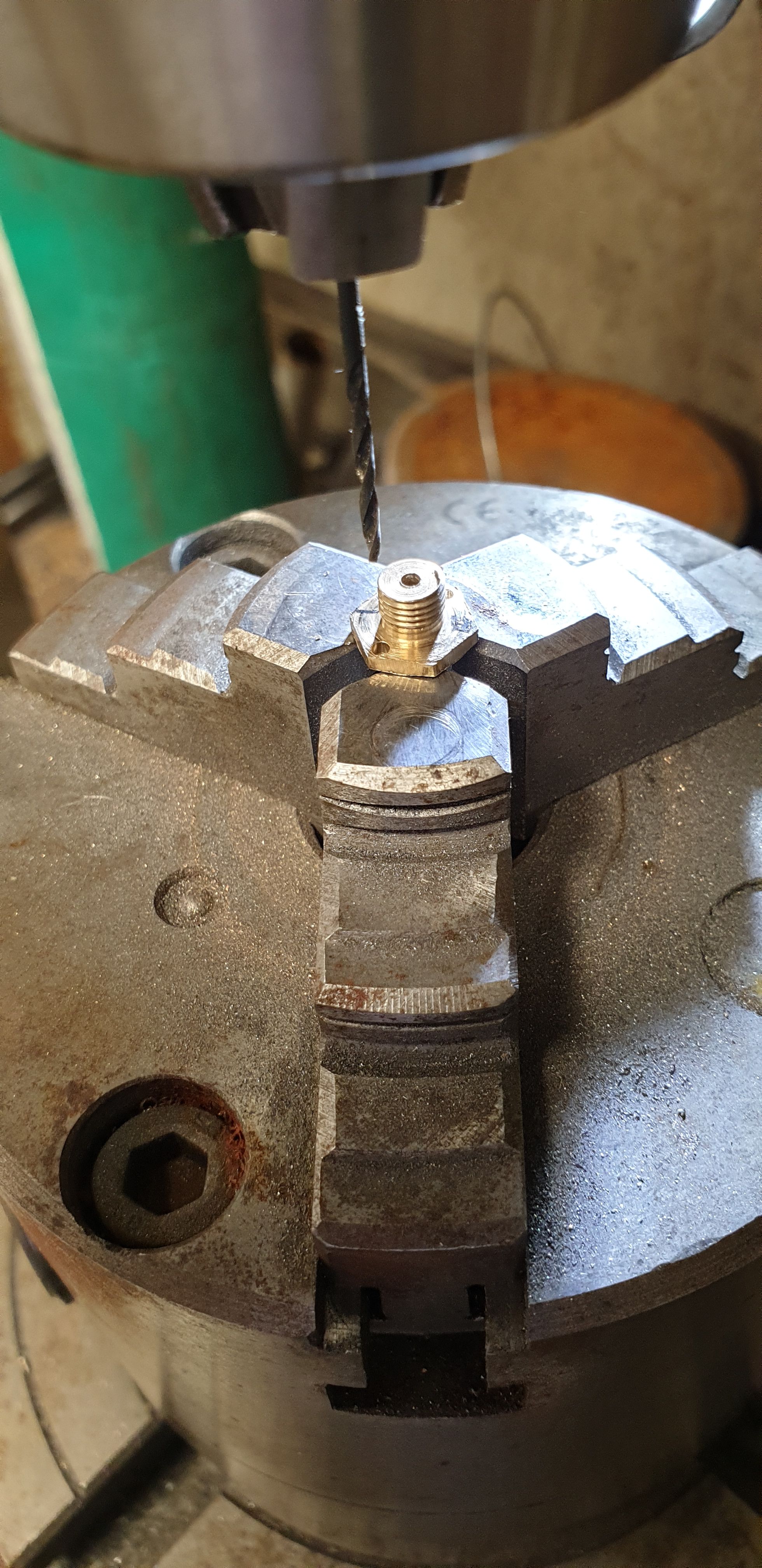
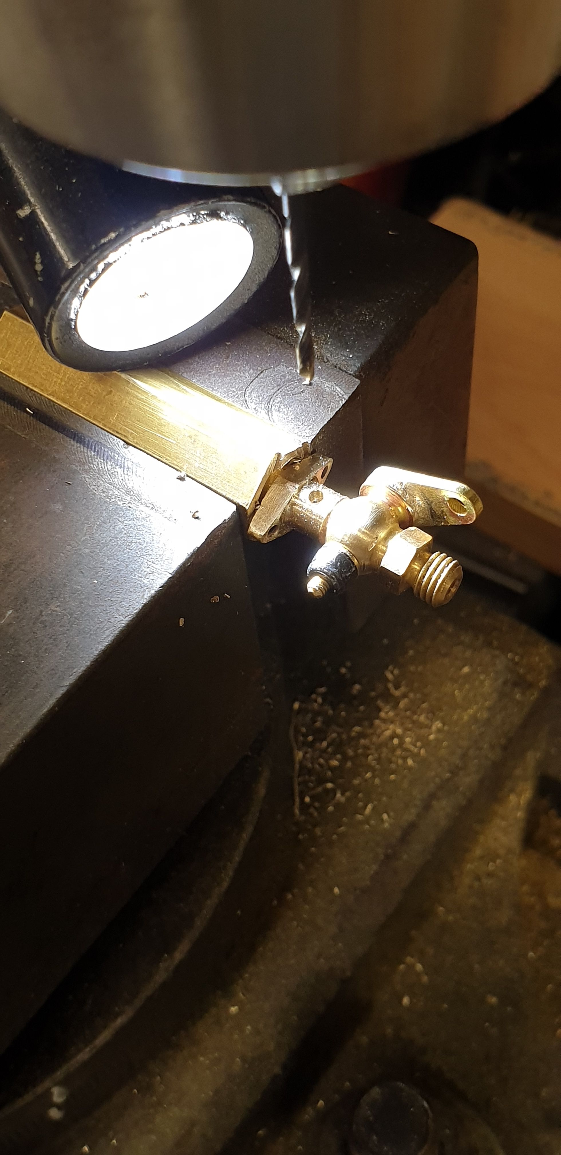
Last time I finished with the relief valve plate blanks having been drilled, before profiling them I decided to complete the body first so that I could work out where best to sit the plates on the body. The first thing to do was to drill the mounting holes into the body flanges, here we see one of the body's being drilled on the rotary table at 180 degree spacing. I worked out the PCD of these holes using the drawing shared last time which looked at the relief valve/draincock head on. These were drilled 1.4mm to later be threaded 10 BA for dummy studs/nuts to be fitted once everything else has been completed, reason for this is that I still have some machining to do first. Although I am using the drawing I am also making allowances for the practicality of the parts and being able to get at them. Therefore some parts aren't exactly to scale although you'd have to know the part very well to tell, as an example the combined height of the relief valve and draincock is approx 3-4mm higher than drawn. BTW, I chose to use Hex bar instead of round as it gave me something to hold better for the various setups involved, for example I could fully tighten the bodies into the hex bar that was used to hold the parts in the chuck, thus be confident of nothing coming loose.
With the holes drilled across the 'points' it was easy to mark out the flange and first cut using a cutting disc and then file to shape. I did it this way rather than on the mill as I had full control of the part which may have come loose using a cutter, that is the rotation of the cutter would undo the thread.
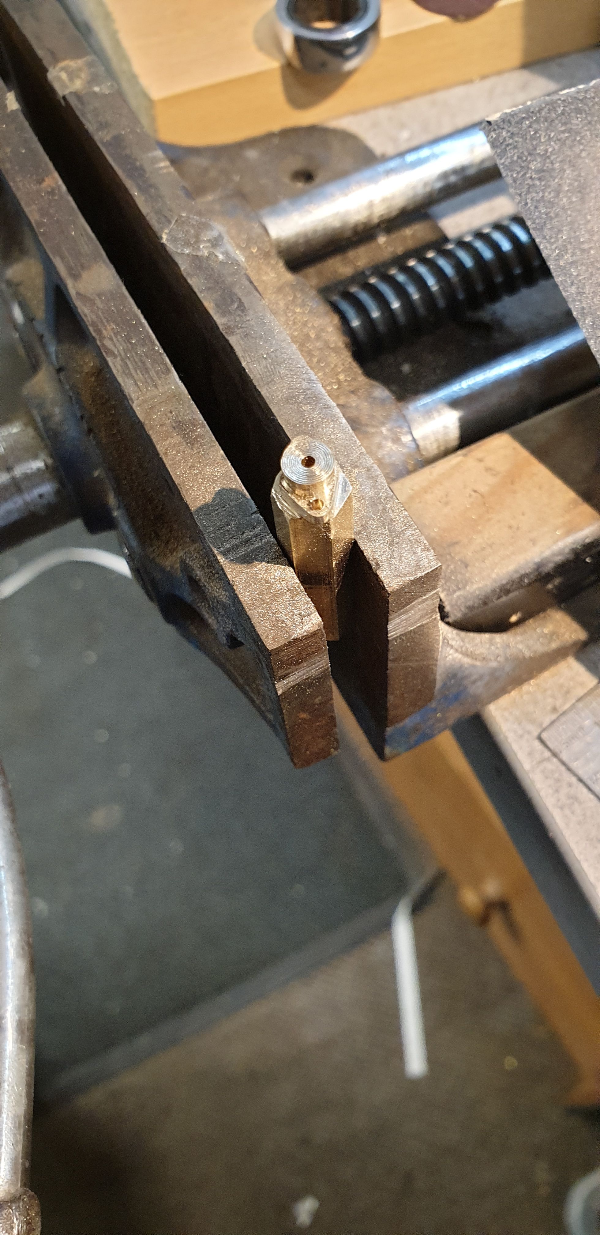
With the body now ready to be silver soldered to the draincock I removed the draincock tap and worked out the orientation for each cylinder. Not only do I have to allow for opposites as per normal but also work out front and back for the thread to fully tighten into the cylinder and also work out the front for the relief valve apparatus, hope that makes sense? With this all noted each assembly was held in a small vice, a suitable piece of piano wire was used to align the bodies. To ensure the wire wouldn't end up also being soldered to the assembly it was first pushed through some bar soap to stop this from happening. I used my smallest nozzle which worked well.
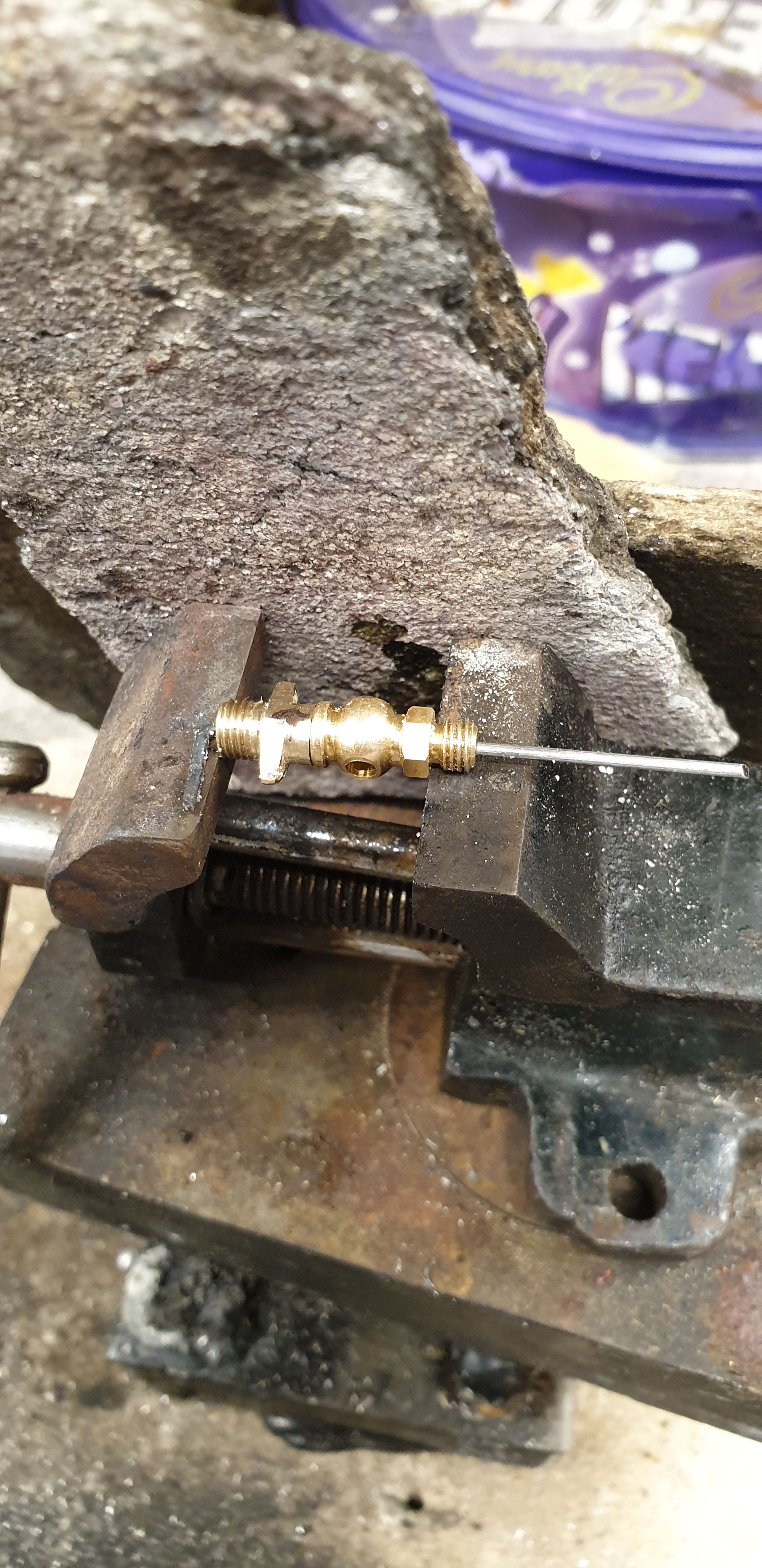
This picture will show my approach in ensuring I had all of the parts sorted properly, as can be seen the first assembly has been soldered ready for machining to size.
Each assembly was then returned to the lathe using again the hex section to hold it in the chuck and then machined down to represent what can be seen in the pictures posted in the last entry. As stated before this is another one of those parts that I have left very slightly oversize, mainly for extra strength remembering that the draincocks will be working below. I profiled another tool for this exercise.
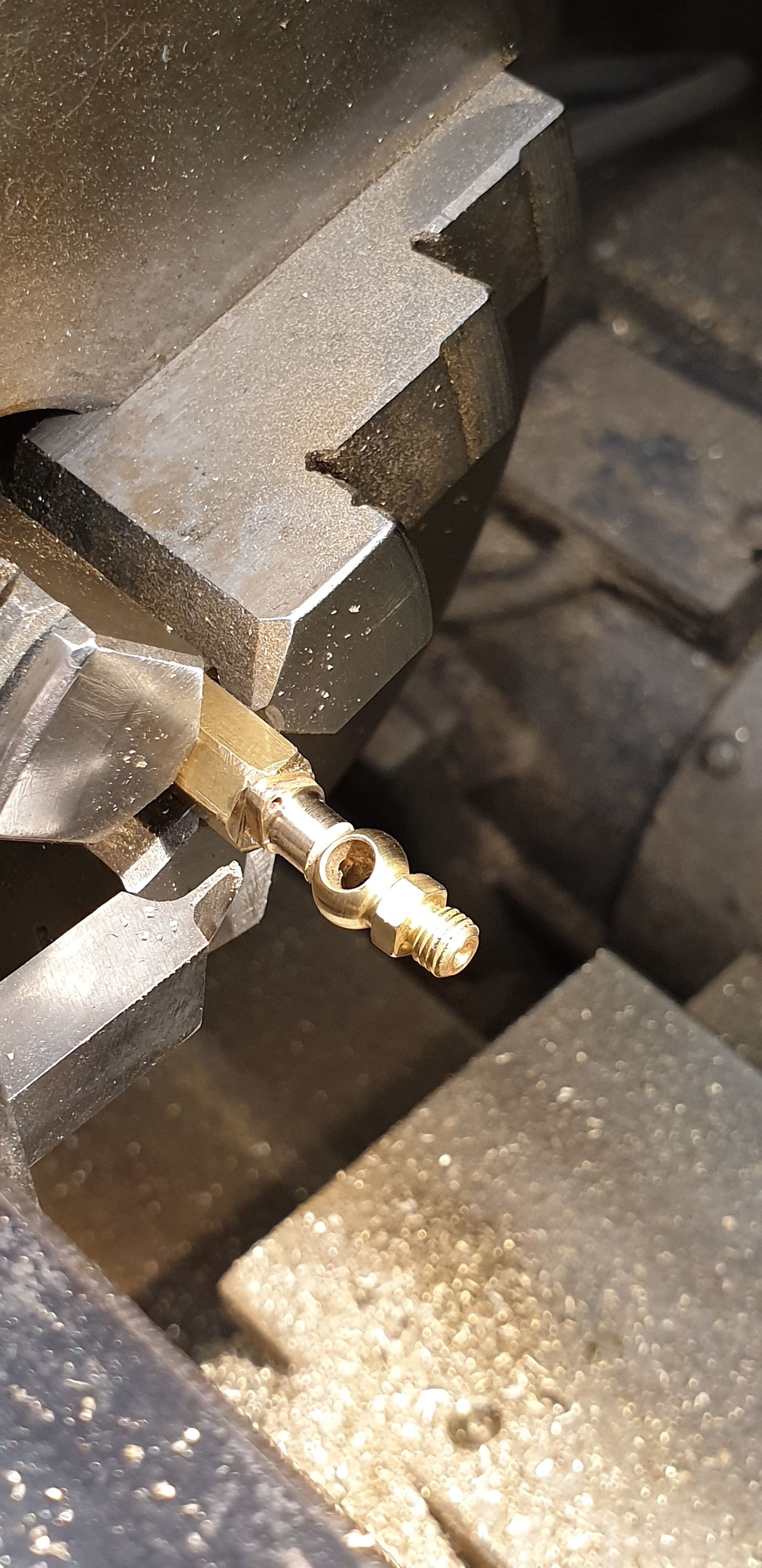
Returning to the mill and still using the hex to hold the part I drilled a 1.4 mm hole into the body for the valve itself to fit, more on this shortly.
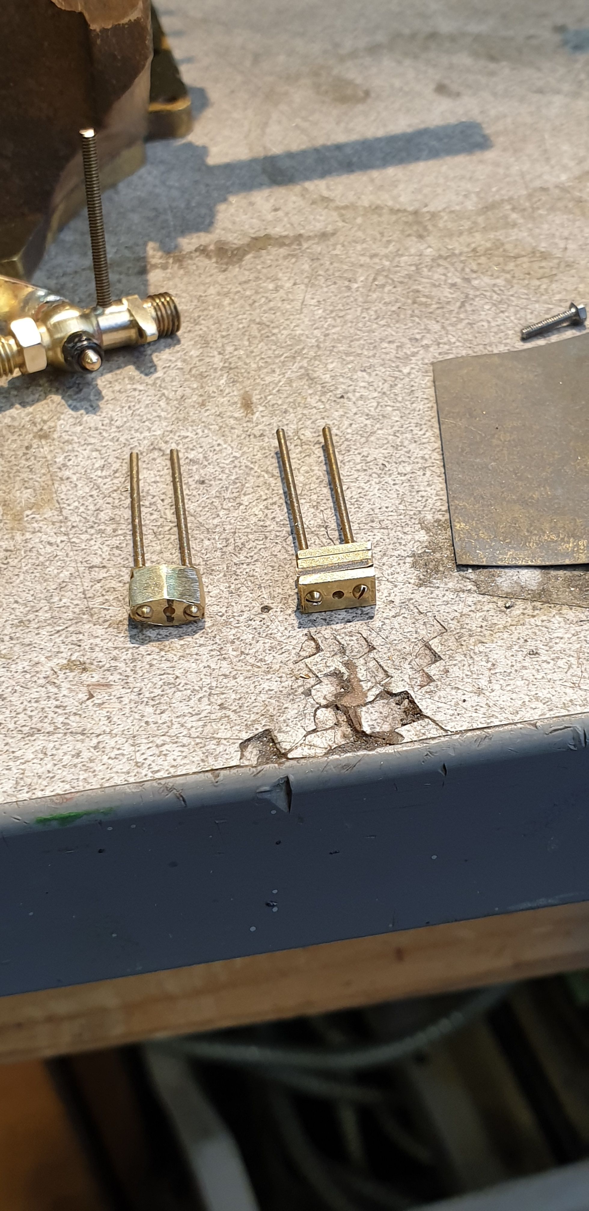
Returning to the plates, I assembled them in groups of 4 using 14 BA screws and filed to shape as can be seen done to one group here. These will be cleaned up more later. I'll explain the assembly a little better while on this picture. There are 3 rods (for want of a better word) between two plates, the central rod is the valve with a spring over it, this is the valve itself, this has a spigot at the end which as far as i can work out allows the front plate to move along. The two outside rods have a threaded section on each end and this is how the pressure is adjusted by screwing in the front plate to compress the spring of the valve. So in the picture we see the 14 BA screws, these will also be used for the final assembly and like the prototype have two nuts on the ends to lock the plate in position, this will be easier to see shortly. You can also note that in the assembly in the background, a length of 10 BA studding has been cut to length and test fitted into the body.
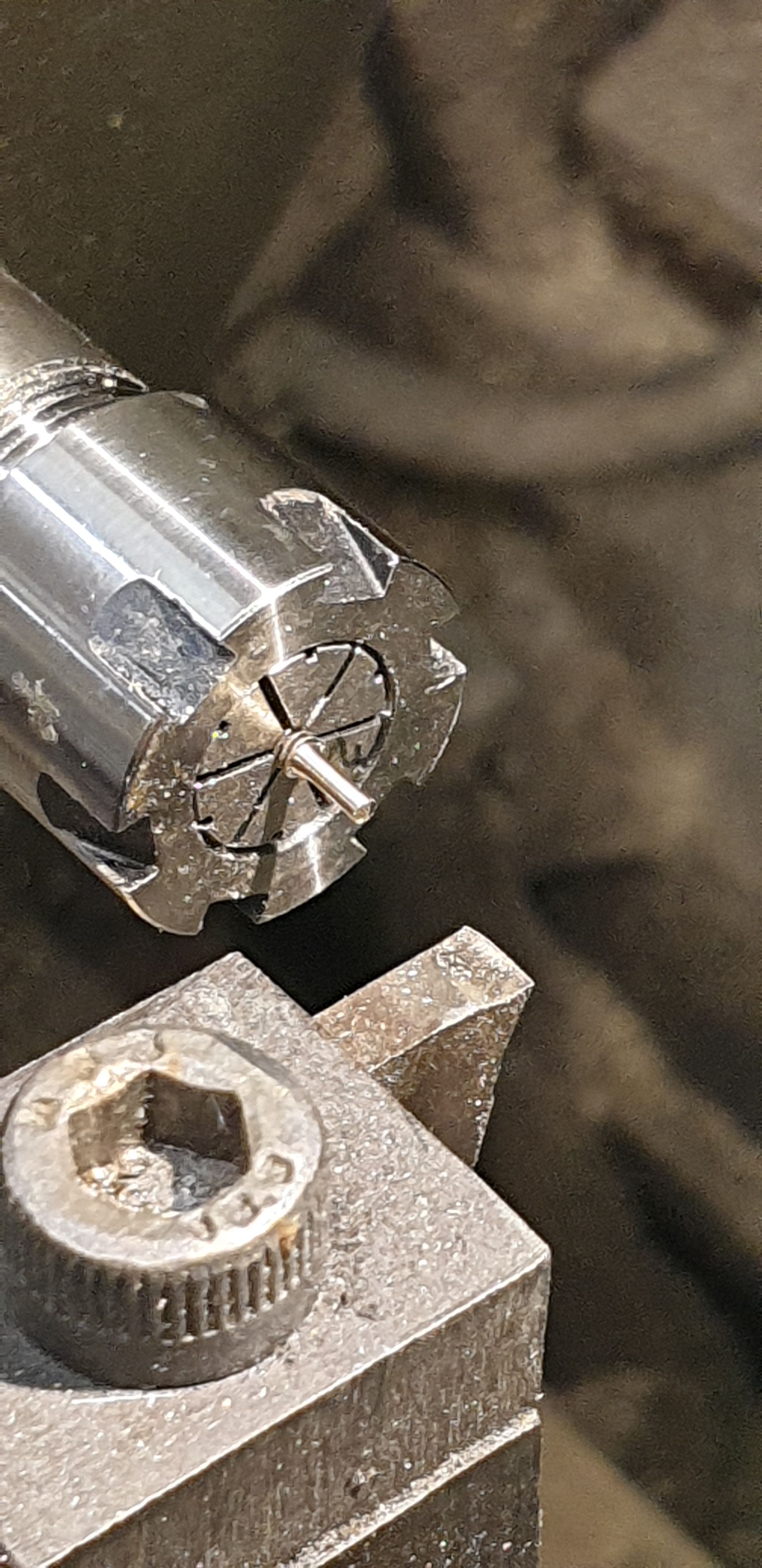
The next job was to machine a small 1 mm wide spigot on the end of each length of 10 BA studding. For this I held each piece in a small collet chuck and machined to size.
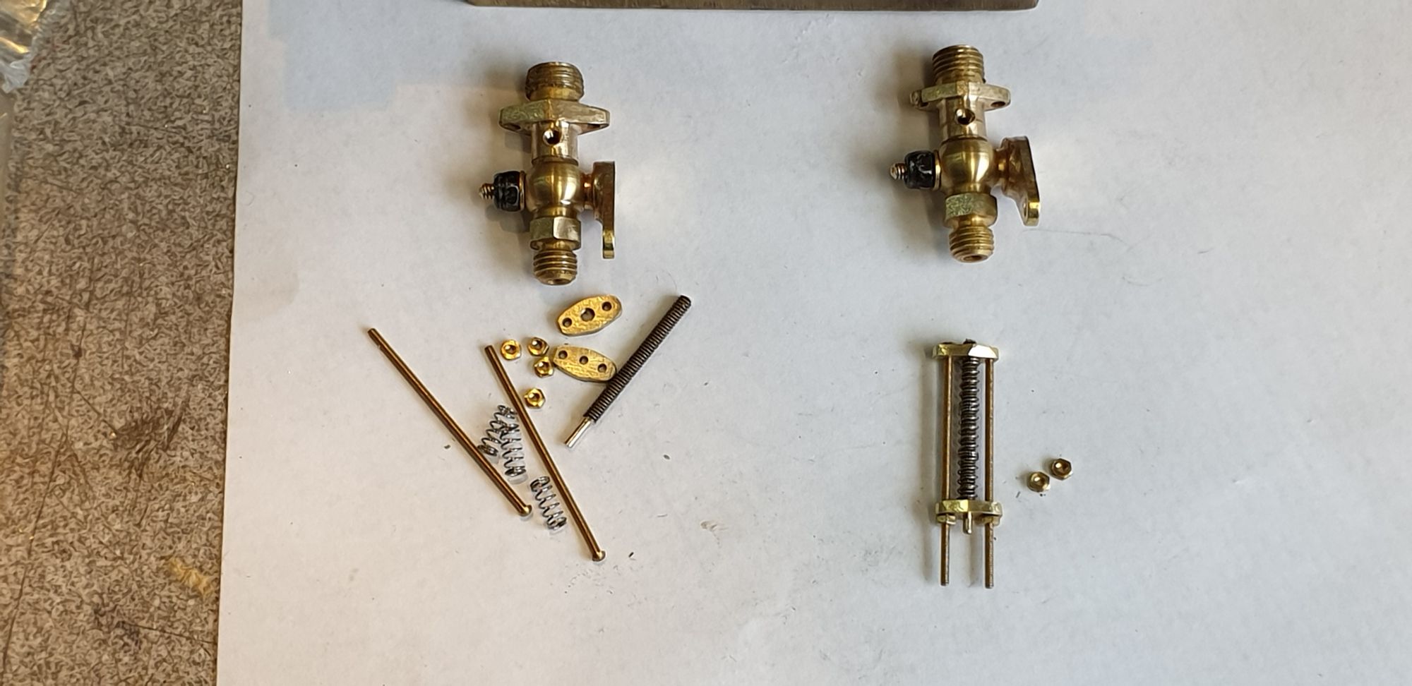
Here I have laid out the various parts involved and also part assembled one of the relief valves to give a clearer look at what is what. The springs are 0.25 mm wire and 5 mm long by 2.2 mm OD, these are a nice fit and once assembled onto the valve they look like one long spring. These parts are very small and a little fiddly to assemble but I have worked out a procedure now and once the cylinders are ready I'll fit them in place. The threaded section of the valve will be secured to the body using Loctite. I was wondering how well this will seal but then thought, why worry, it it leaks it will just look like working relief valves, I'm pretty sure that the Loctite will do the job though...:)
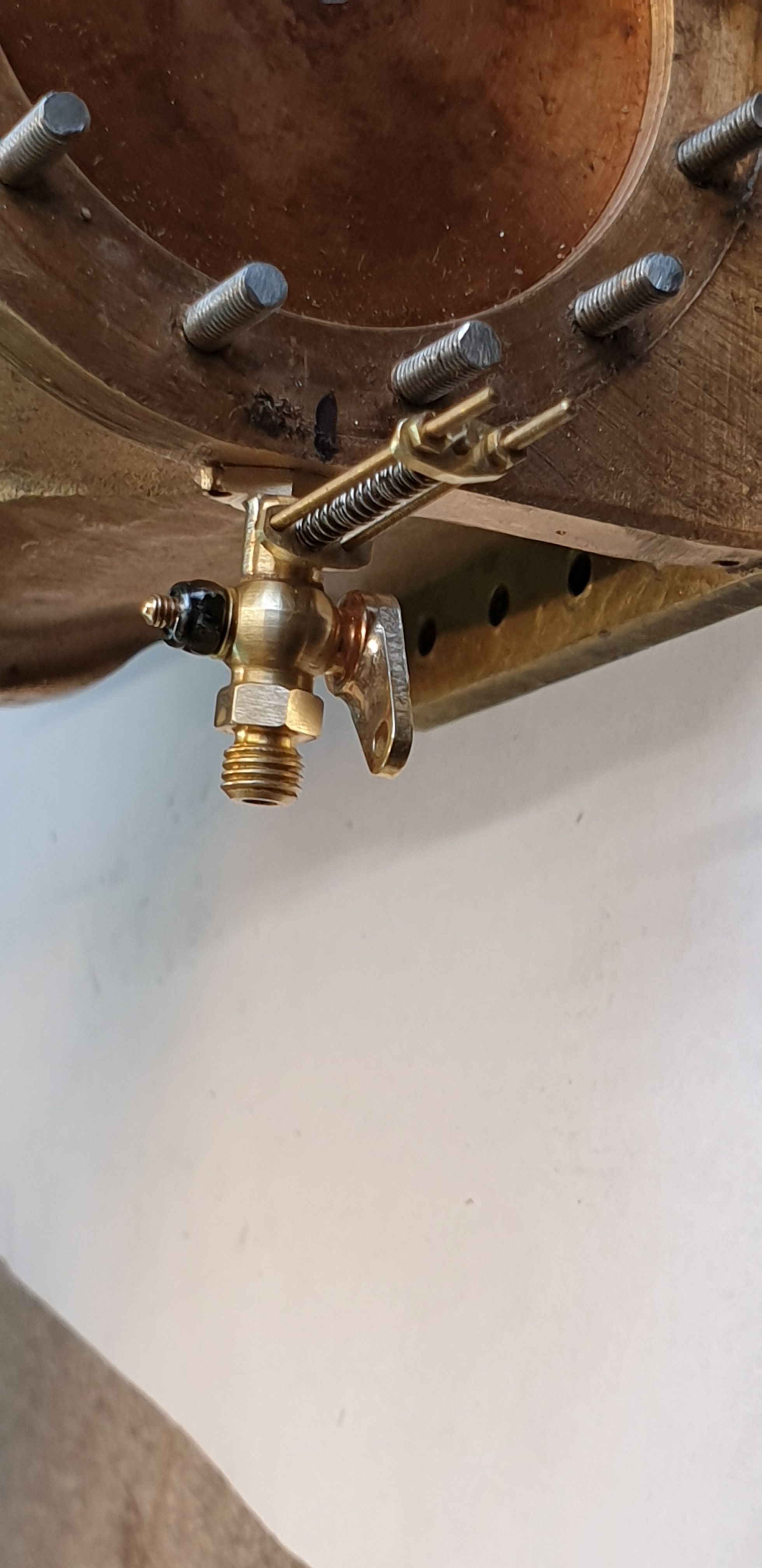
Last picture for this entry, I thought that I'd try one assembly in place to see how it looks, In this close-up I can see that I have a little more profiling to do on the plates, I haven't fitted the dummy 10 BA studs/nuts to hold the body to the cylinder yet and also the 14 BA screws will need their second locknut fitted and then finally cut to length, all in good time...:)
One thing that confused me for a while, if you look at the close-up pictures that I showed last time the relief valve adjusting rods and valve springs look much shorter, this threw me for a while. Also I couldn't work out why one of the valves had the rods bent over, in fact I didn't even realise that it was the rod that I was seeing to begin with. It then dawned on me that perhaps this valve had been damaged and had it's valve assembly knocked accidently. However, on closer inspection and using what I have now learnt about these valves being made redundant once the bigger relief valves had been fitted into the cylinder covers, I'm more in mind of these valves being deliberately bent over or even cut short to hold them permanently closed? This makes complete sense to me but I have not read of this practice anywhere?
Next time around I'll get the cylinders in paint and hopefully permanently fitted to the frames, there's a lot more to do first which I'll cover in detail in the next entry.