
I've been busy over the last few days and getting very close to the final fitting of the cylinders, unless I have forgotten something, of course.
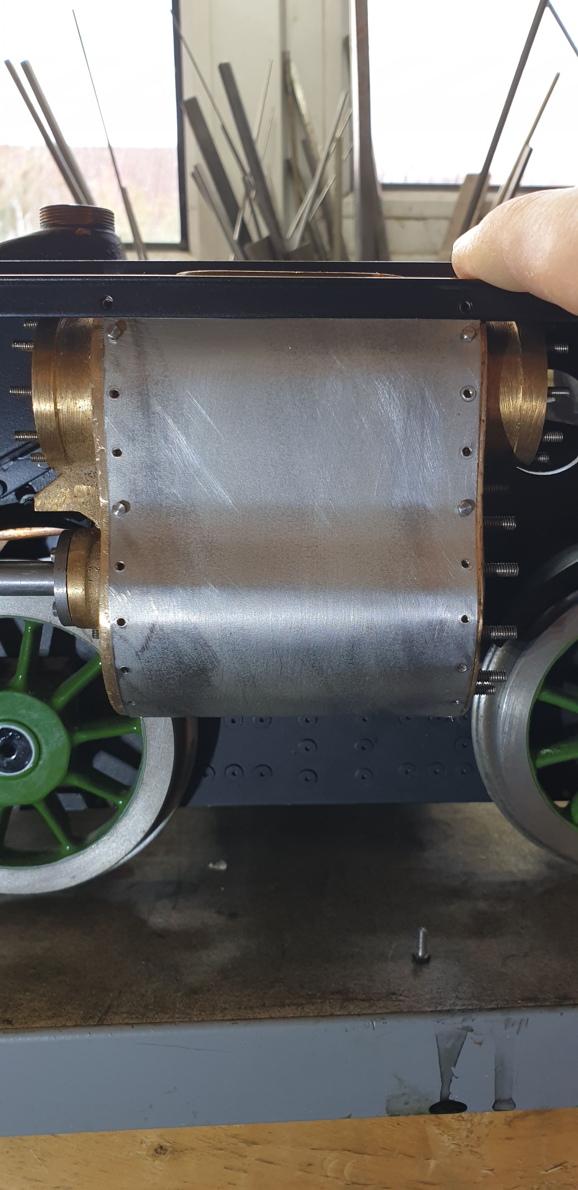
First up was to shape the cladding, this time around from 'Tin' to hopefully give a stronger article and less likely to dent. In the first picture for today I am doing the final 10 BA bolts for the cladding. I shaped the cladding partly by hand and in the 'formit' leaving both ends overlength until I was happy with the fit. Two things to point out here, first, as can be seen I have decided to cut around where the draincocks fit rather than cut a hole and let the draincock hold the the cladding in place in this area. The reason for that is due to the relief valve bodies not having a round mount to help seal the part, I decided it best to have a solid contact with the cylinder itself. The other thing to note is that here I have taken the cladding underneath right up to the flange, this of course would not work as I'd have to remove the cladding to get to the bottom row of mounting bolts which also double up to secure the front bogie. I thought this could be problematic during any future maintenance which required removing the bogie. I have no idea how the full size is fitted here but since it's out of sight I'm happy to remove the offending part.
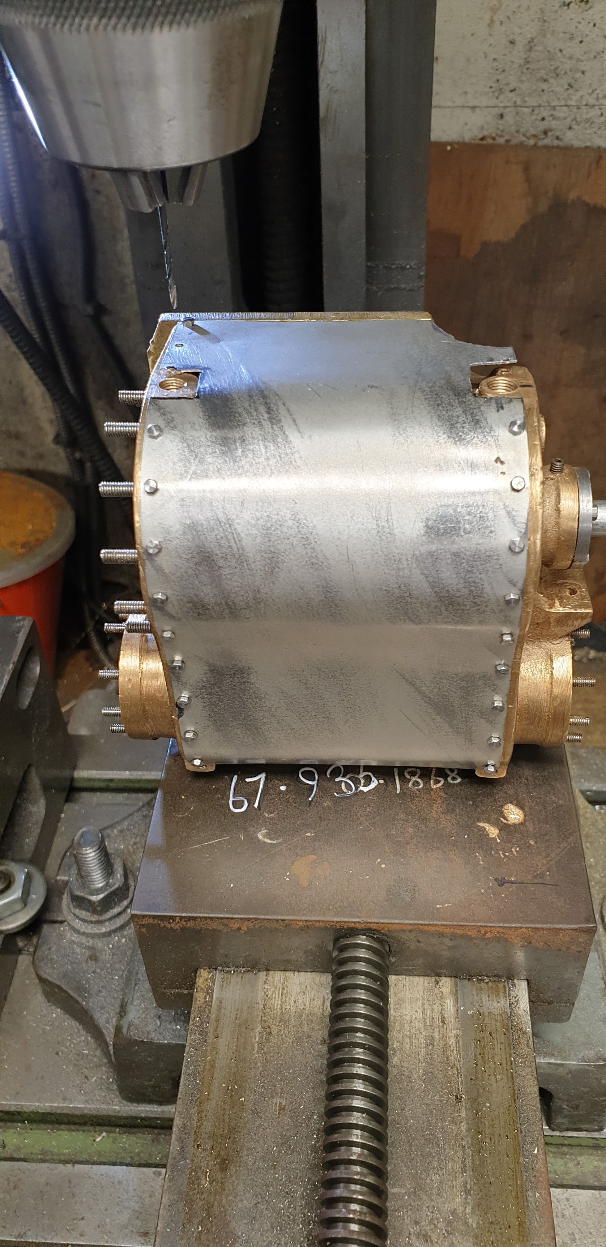
A top better view to show the part that I later cut off, I also repositioned the last two mounting holes to hold the cladding firmly at this end. The black marker pen is where I removed more metal before making good. Note how the casting isn't square in the bottom of this picture, it's good at the front but the back is a different thing altogether, I'm not going to worry about this as it's just the casting and if you look at the full size, well those have their own problems..:)
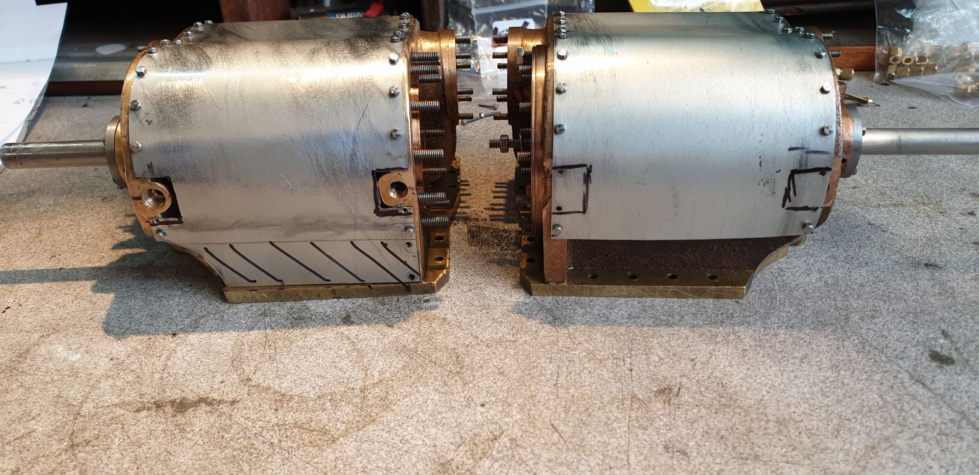
Here we see the underside of both cylinders, now that I had a plan for the first cylinder I then began doing the other one to match.
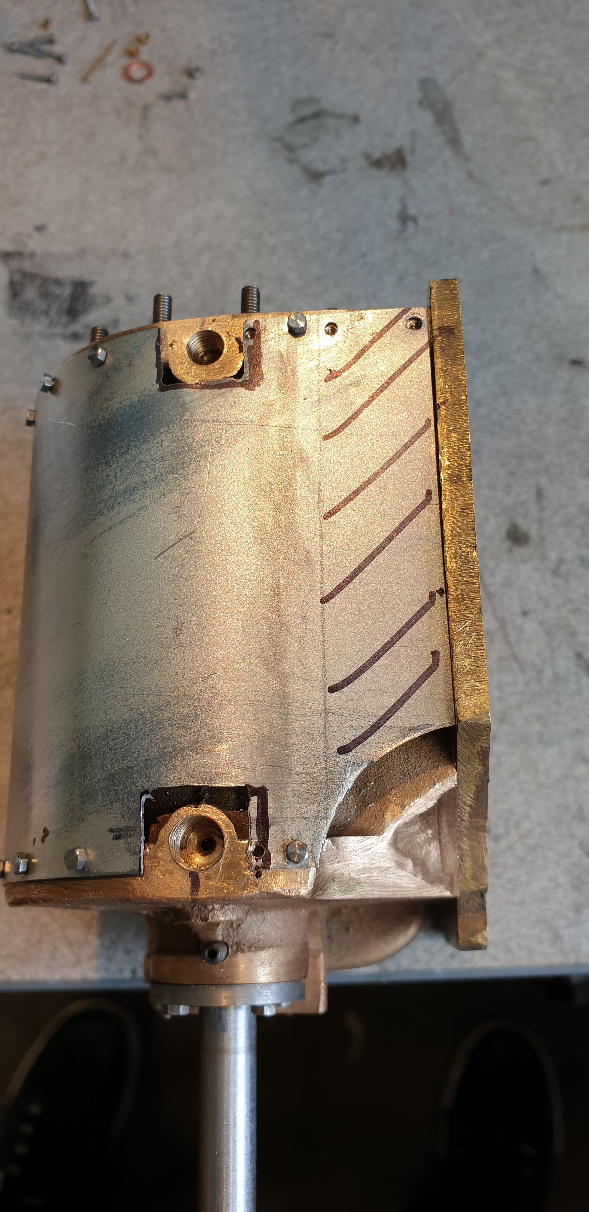
With the cladding now held on with a few bolts and happy with the bottom I then needed to trim the top to get a good fit close to the running board. This picture shows the result, now it looks like it's too far towards the front but this is where the poor casting comes in play. If you look closely, you'll see that the rear face of the casting angles away from the middle, both top and bottom angle out and so I took a position which looked best in the given circumstances and trying to keep the gap at the front similar to full size. The casting for the other cylinder is much better than this one. Talking of 'full size', from what I can tell it looks like the cladding sits in a small recess, this wasn't an option, especially considering the rear of the casting which ruled out attempting it using a router. This and also the fact that where the cutout for the running board fitting bolts are, these are at the same depth as the steam-chest wall, so recessing the 'webs' for the cladding to sit in would mean cutting into the side of the steam-chest. This was why I first chose 10 thou brass as it's very thin but the 13 thou tin look's just as good.

Before painting the cylinders I first fitted each cylinder along with the main running boards and the top running boards to mark out the access area for the main steam-pipes
Next the cylinders were painted in the same 'Eastwoods' radiator satin black as used for the middle cylinder, this is an etching type pf paint which is painted directly onto the metal, only time will tell how well this paint works.
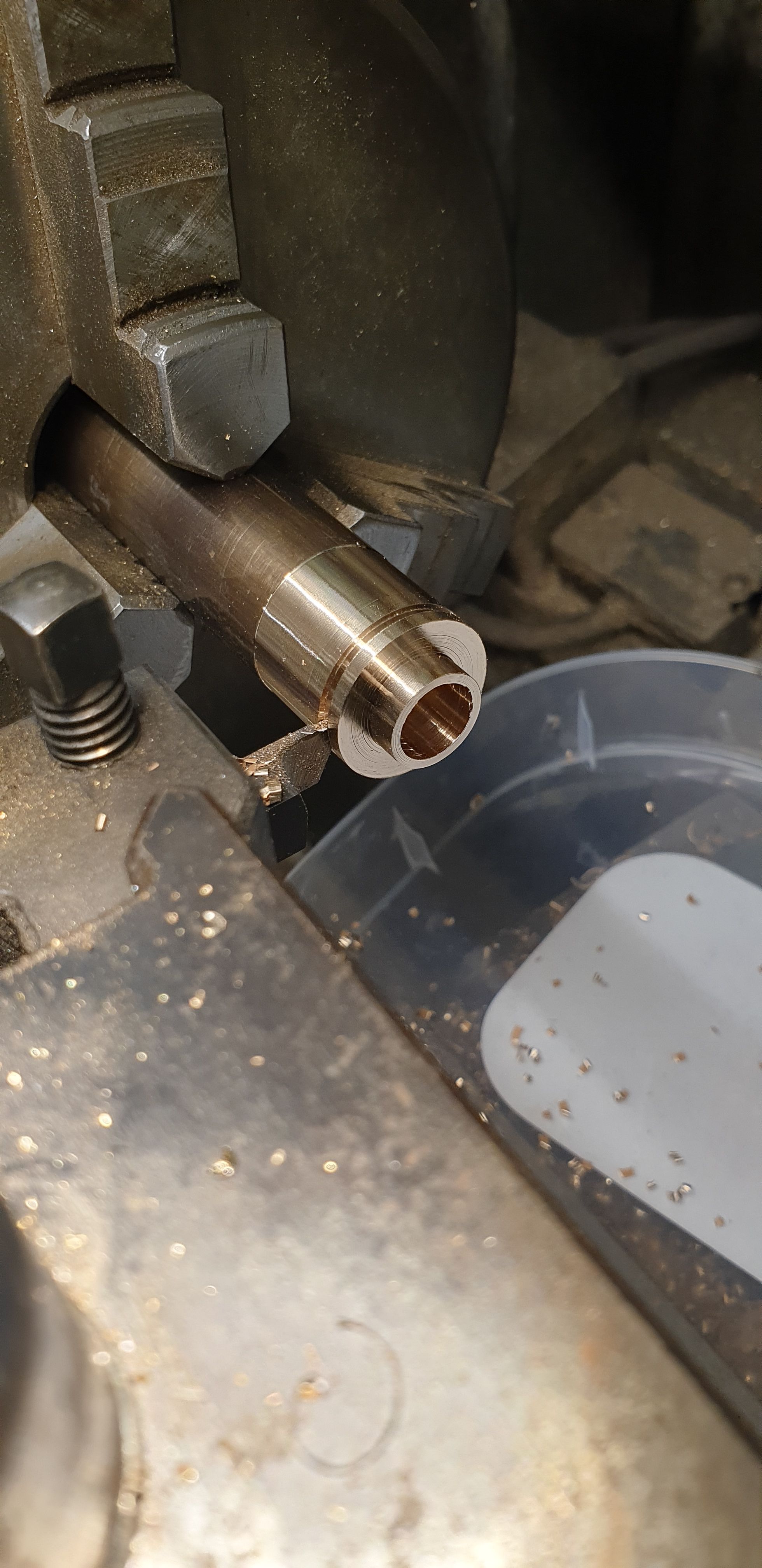
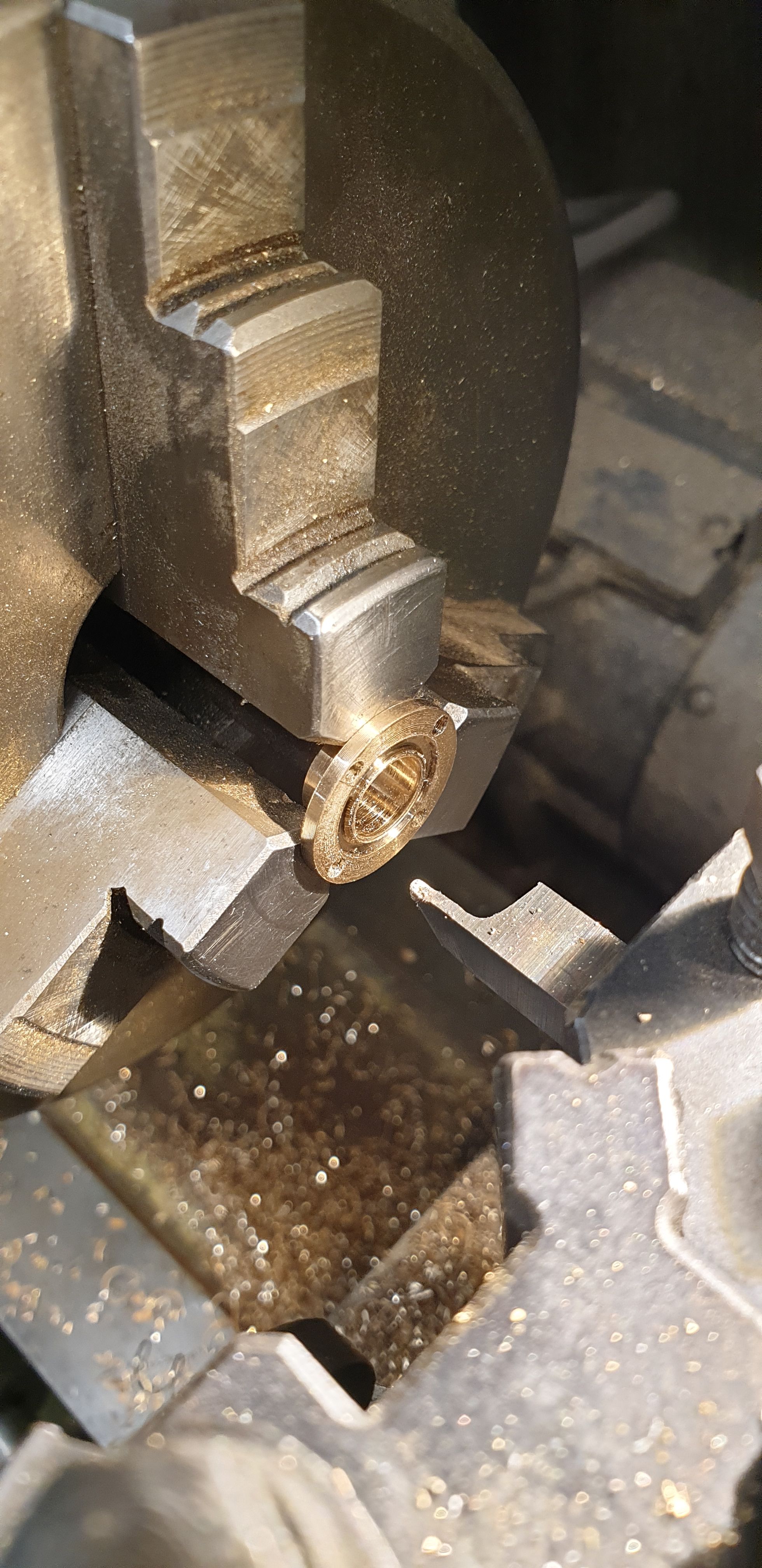
Then I moved onto the steam-pipe flanges, Don has these as plain discs, 3/4 x 3/32, I have kept the 3/4 and close to the 3/32 but have added a spigot for the 3/8th x 22 swg copper pipes to fit into, I see this as both being easier to silver solder together and also a stronger joint. I have made mine from bronze, the picture shows the first flange being parted off.
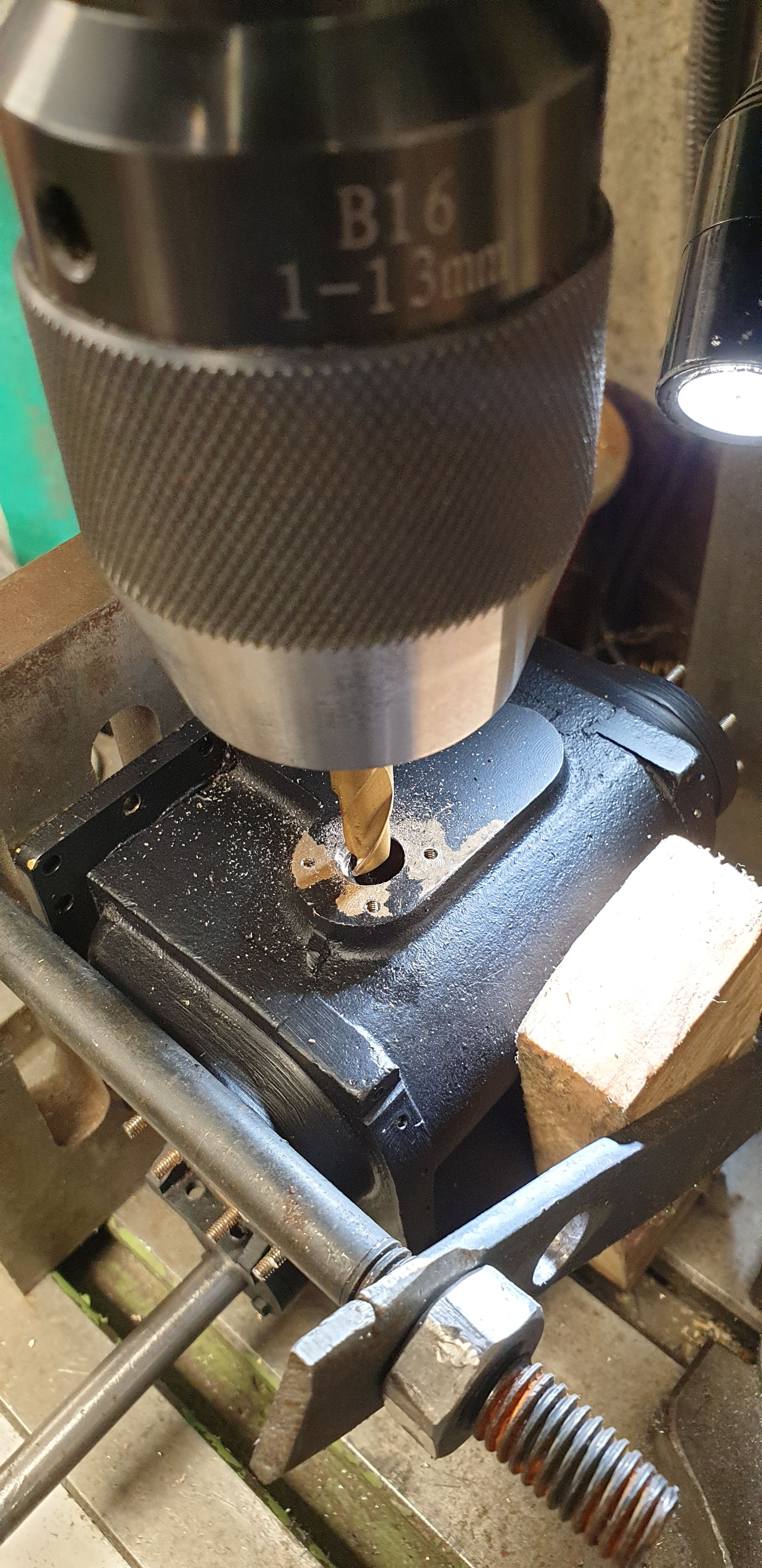
I forgot to take a few pictures but basically these were just the flanges being drilled on the rotary table at 90 degree pitch and those holes then being transferred across to each cylinder, drilled and tapped 8 BA. This next picture shows me opening up the angled hole as shown by Don and making it vertical for a short depth to ensure there is no step that would effect the exhaust flow. At first I got carried away and began drilling a 3/8th hole to match that of the flange, I quickly realised that this would be too big as I hadn't allowed for the wall thickness of the copper tube, I then changed to an 8 mm cutter and finished off with the Dremel and a grinding tool.
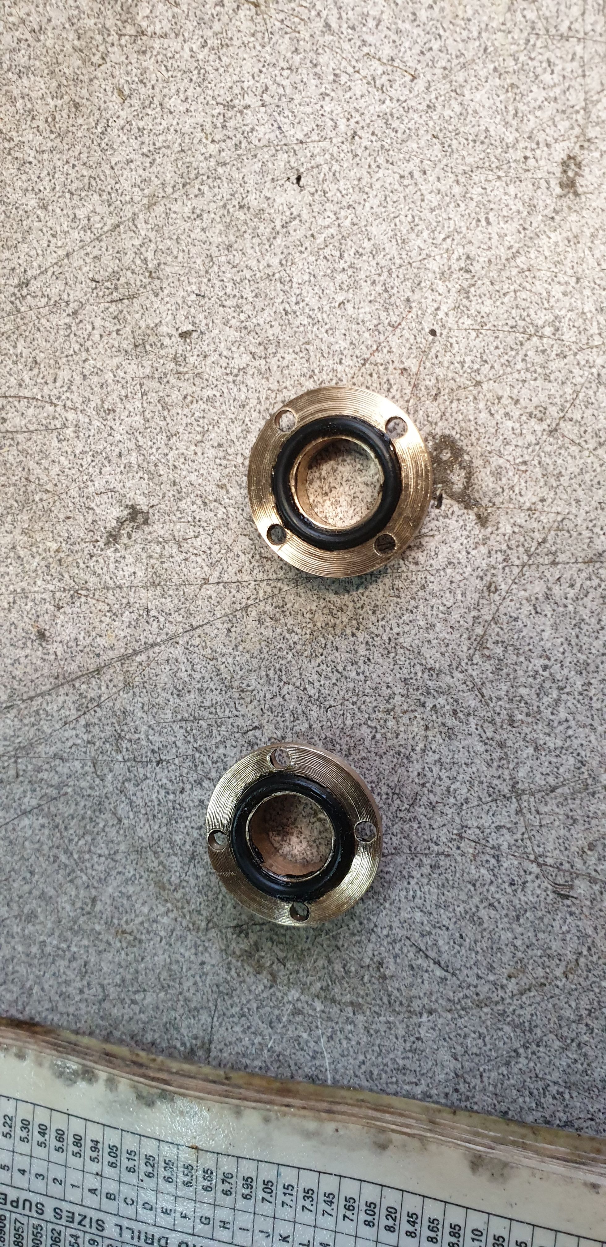
I then returned to the flanges, here I have deviated again and added an 'O' ring rather than rely on a plain gasket, here I have machined the groove for the O ring. When making these I considered ahead of each stage that I was going to fit an O ring, therefore the PCD of the mounting holes and the size/position of the O ring were taken into consideration first.
To make life easier when mounting the flanges to the cylinders I used a small amount of the high temp silicone used for sealing the exhaust outlets to hold the O rings in place.
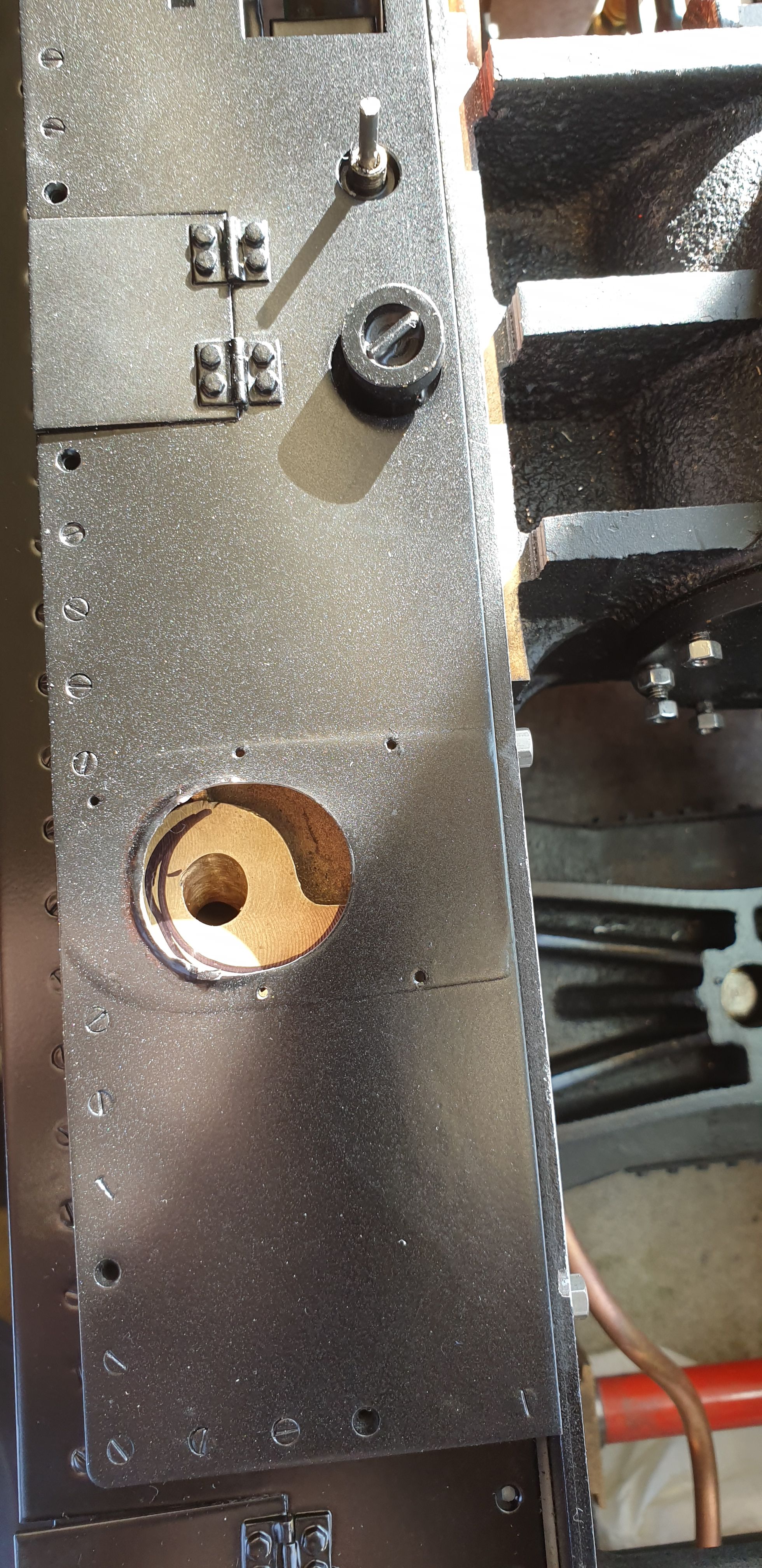
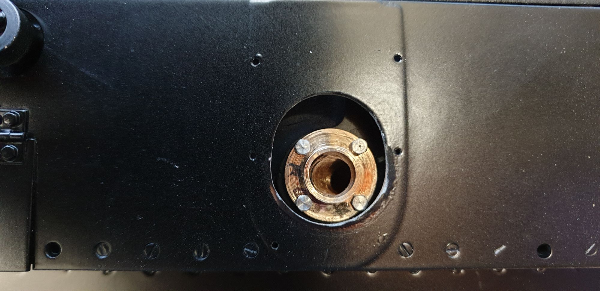
Here's one of the flanges bolted in place and viewed from the top running board opening. As can be seen I have begun opening the hole a little, I decided to do this to give a better access to the bolts if I needed to renew the O rings at any point in the future, doing it this way means that I won't need to remove any of the running boards. You may note that the paint is burnt and the hole (well it will be an oval) isn't symmetrical , I started with a sanding wheel in the Dremel but this was causing the paint to blister, no surprise really. Later I will finish off to the marked pencil line using a file, looks a bit rough at the moment but will look fine once finished. The footprint of the steam pipe cover seen shows how much room I have to play around with here and why I am enlarging the hole for better access. I'm considering changing the bolts for stainless studs/nuts, might be a better idea and easier to line up the flange when fitting during any possible future overhaul.
Last thing to do was to temporarily fit the cylinders, running boards and see if I can get the pistons and valves out while the cylinders are fitted to the frames, as per full size. I took a short video to show this, oh and I even added some audio, lucky you...:)
Over the weekend I'll go through everything again just to double check that I haven't forgotten anything before fitting the cylinders to the frames for the last time. Once that is done I'll make the remaining draincock linkages and shafts and fit the draincocks to the cylinders. Refit the cab and check the draincock operation. The cladding has been painted and put away to harden, once cured I'll add the vermilion lining and fit to the cylinders, there will also be a layer of insulation between the cylinder's and their cladding which will be added at the same time.