

The sum of the parts involved in this design are a little bewildering at times and trying to work out what can be done and in what order is no small task in itself. It's a simple matter of big fat fingers can't fit in tiny spaces and thus I need to make things which one may think could be done later. The draincocks are such a part, just as the brakes and sanders were before them.
Thus Before I can fit the cylinders I needed to make/fit the draincock linkage first, purely because it's easier to get to without the outside cylinders getting in the way. This entry will cover the middle cylinder, now I hold my hands up to an error on my part here which although isn't a disaster it does mean that the draincocks will open in the opposite direction to what they should do. What I had failed to realise when setting the cable position was that the middle cylinder should open in reverse, that is the draincocks open backwards which would then mean the outside cylinders would open forwards as they should. This will become clearer when I get to the outside cylinder, I'm not going to change it now and will live with it as it is.
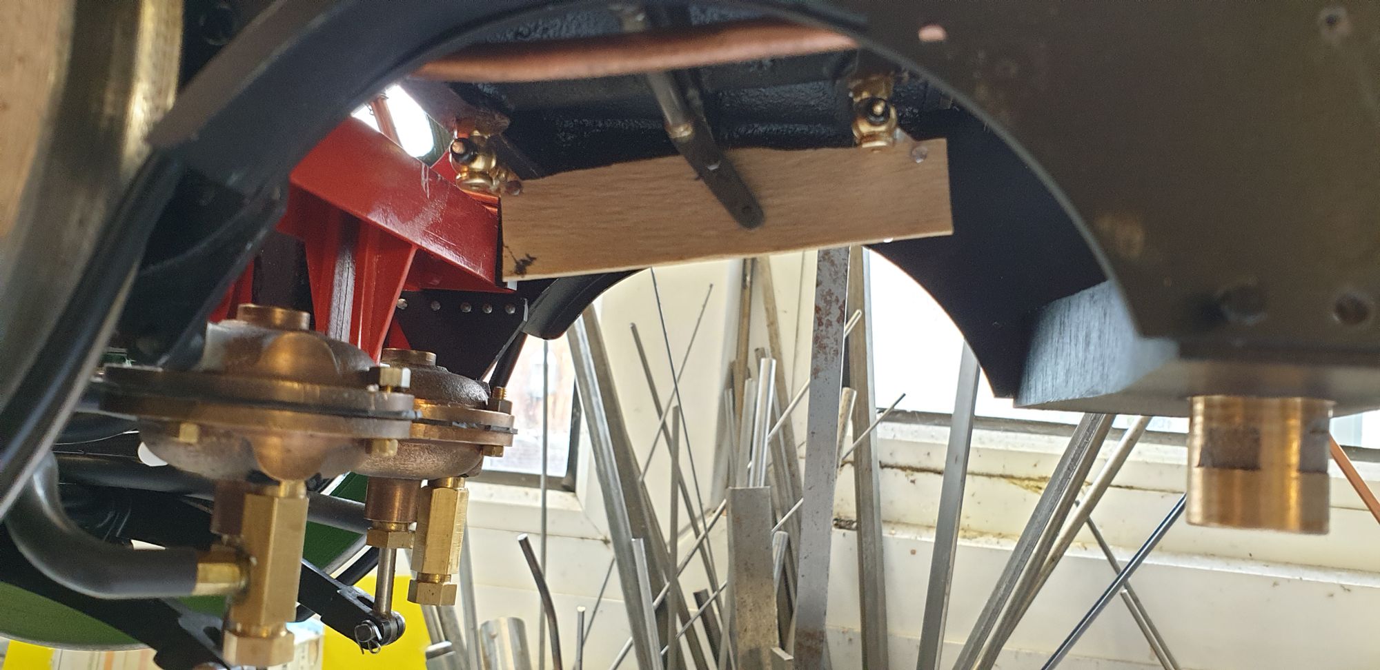
So, my first part to make was the trunnions which fit on the inside of the frames to hold the cross shaft for the outside cylinders. The first picture shows the trunnion blanks in position and the 3/32 cross shaft blank in place to check all was square.
Don mentions that if there's any flex in the shaft that it can be increased to 1/8th, I will stick to 3/32 as I have other plans to both reduce any flex and also to both keep the shaft central and also make it removeable without having to drop the trunnions. BTW, the trunnions share the bottom two forward holes for the cylinder flange mounting.
As stated in the last picture at this stage the trunnions are just blanks, ie not shaped or made to final size yet. This picture shows that I have scribed out on the blank the apporx shape that the trunnion needs to take.
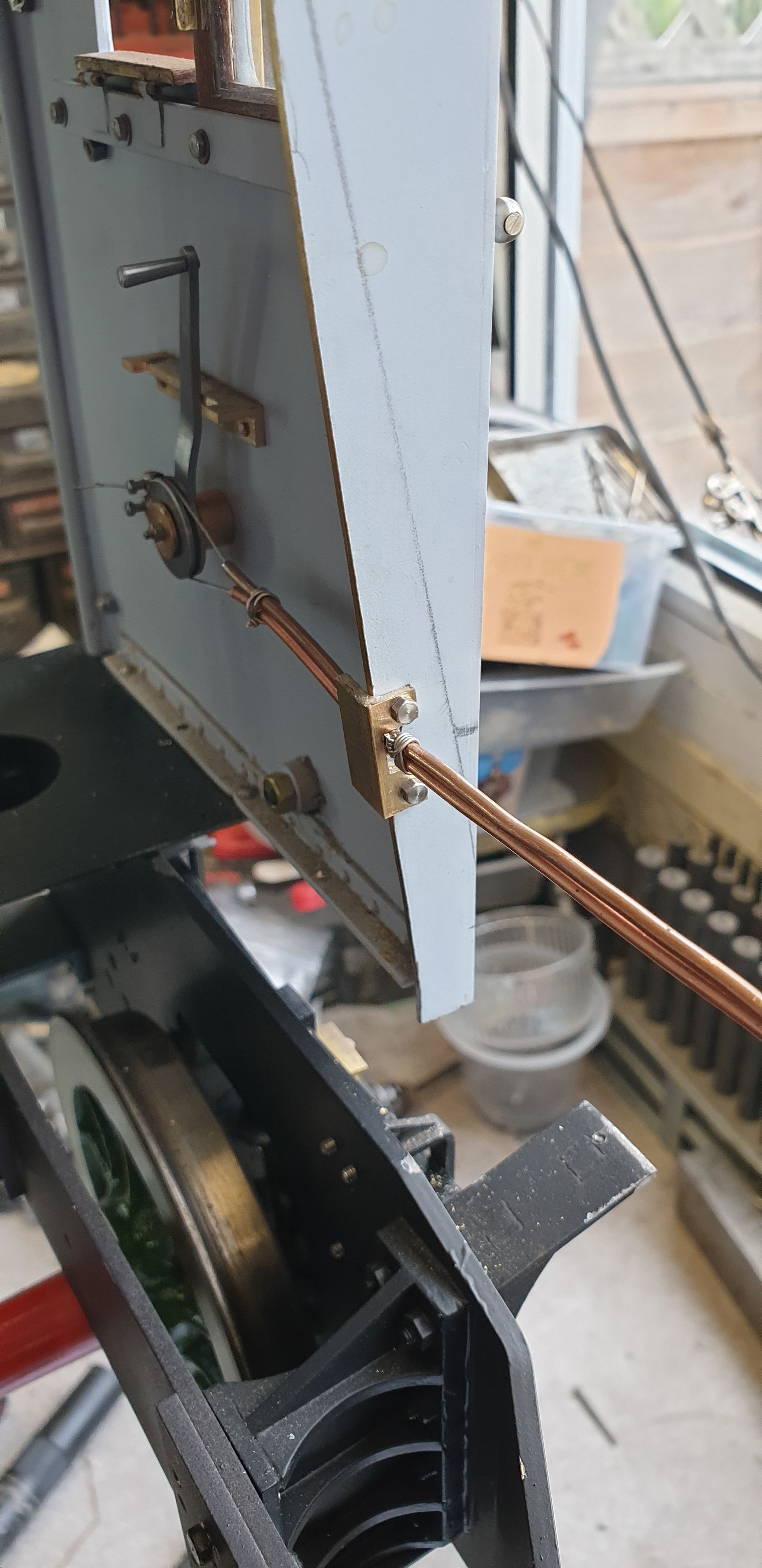
With that done I now moved back to the cable as there were a few bits that needed my attention, first was to stop the outer Bowden cable tubes from being able to slide within their mounting clips. I didn't want to grip the tubes any tighter for obvious reasons and so tried some double sided tape around the tubes and squashed between the body and cap of said clips. This held the tubes very firmly with no movement whatsoever, i was happy with that. Next was to secure the tubes to the cab spectacle plate. The cab was refitted as i need it to operate the draincock mech and also I needed to secure the tubes to it. The picture here shows that I have added a short length of brass angle, bolted to the front of the spectacle plate. I will later need to trim down the inner face but will wait until I know by how much when the boiler is ready to be fitted. The front face will be hidden within the cladding, you can see where the cladding sits by the pencil mark showing it's position.
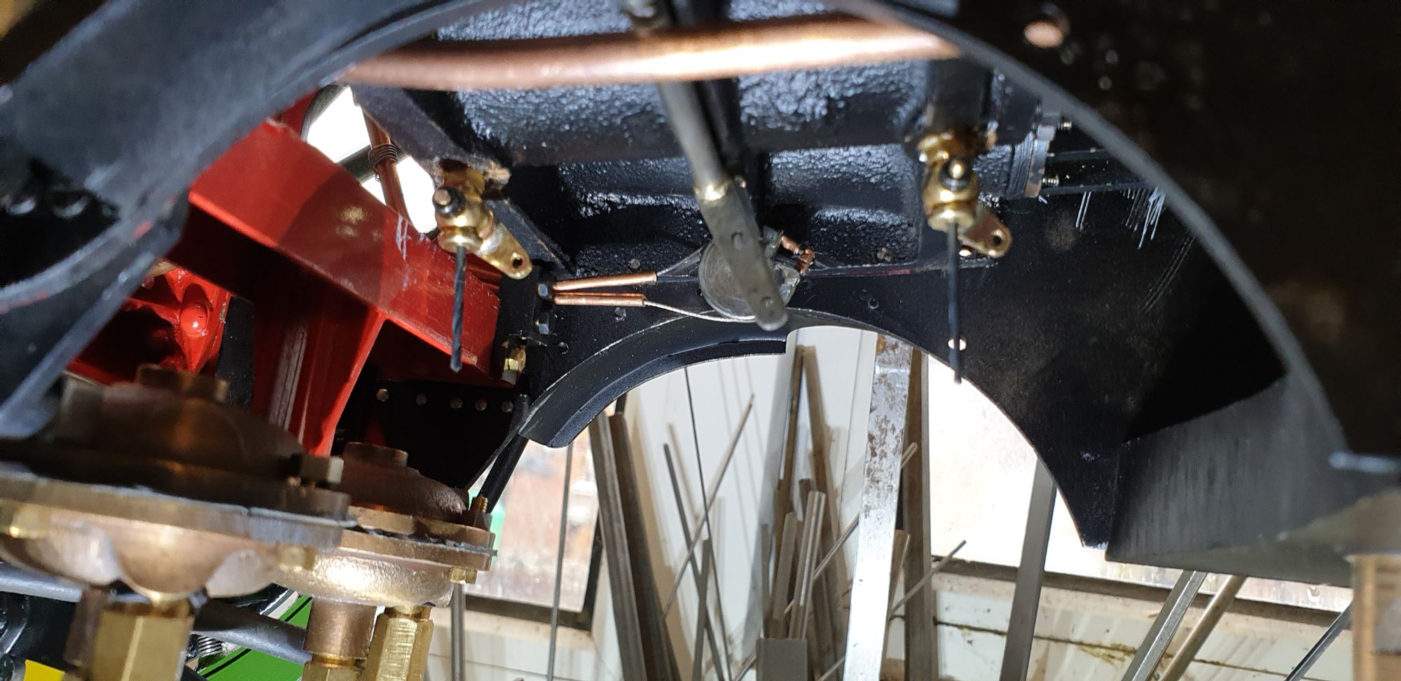
Next job was the linkage on the middle cylinder itself, the first job was to fit the draincocks, you may note that I haven't added the relief valves to these, I think I have more than enough work to do without making those to never be seen...:) Note that I have placed suitably sized drill bit ends into the draincocks to hold them fully open.
I then ensured that the cab handle was also in the open position and using a small section of a wooden tongue depressor I marked out where the holes needed to be.
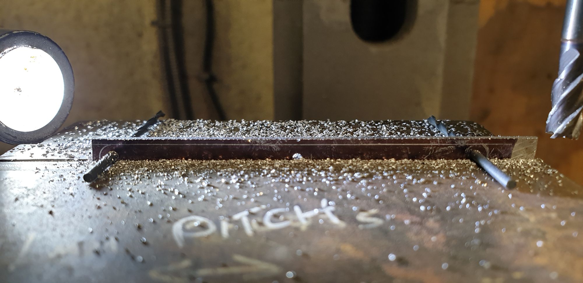
With the holes plotted I transferred them to some 1/16th thick steel plate and first drilled the holes and then machined to size, here we see one of the edges being machined using drill bits through the two outer holes to keep things level.
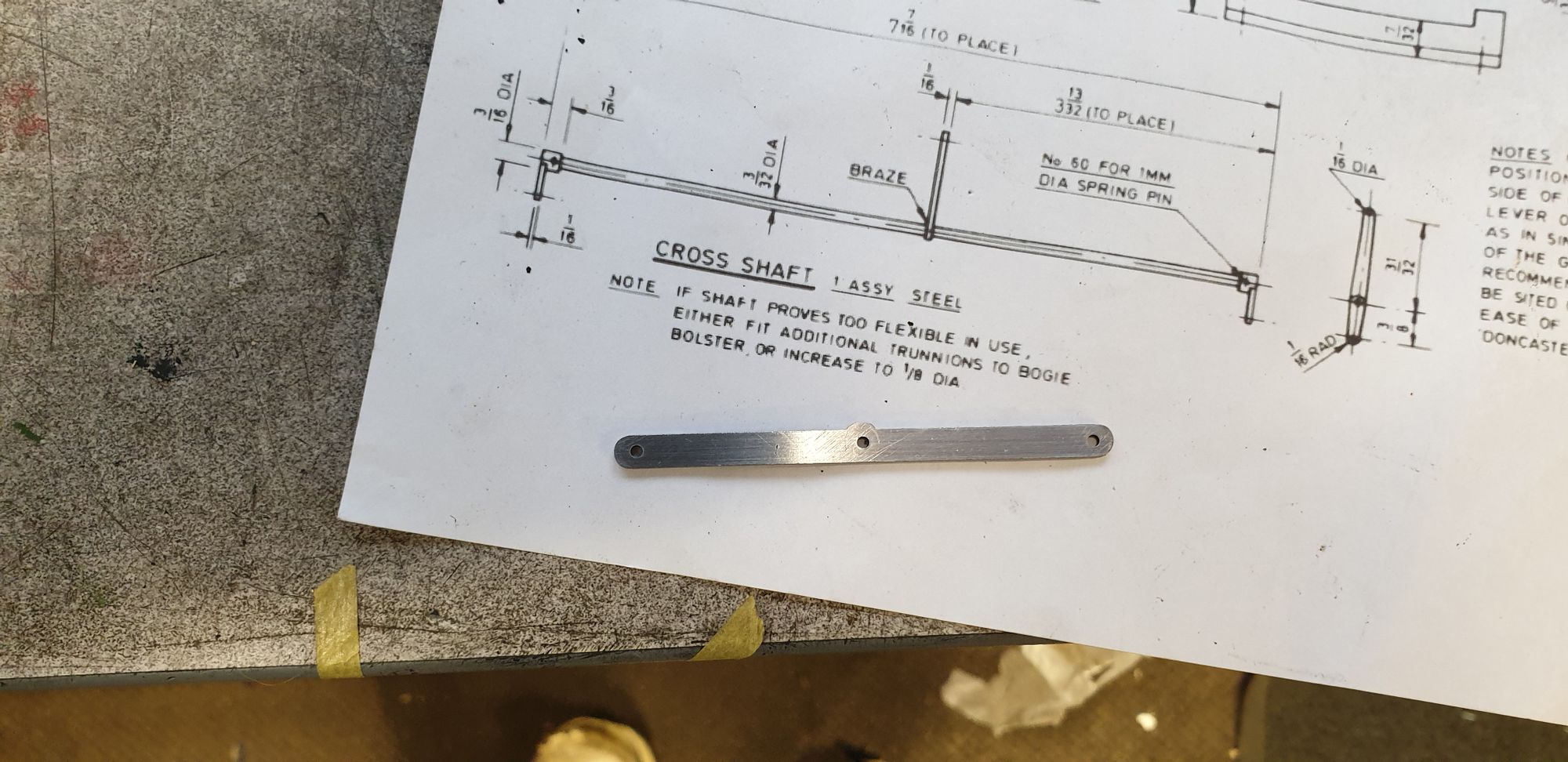
Here's the finished link and also the outside cylinder cross shaft drawing.
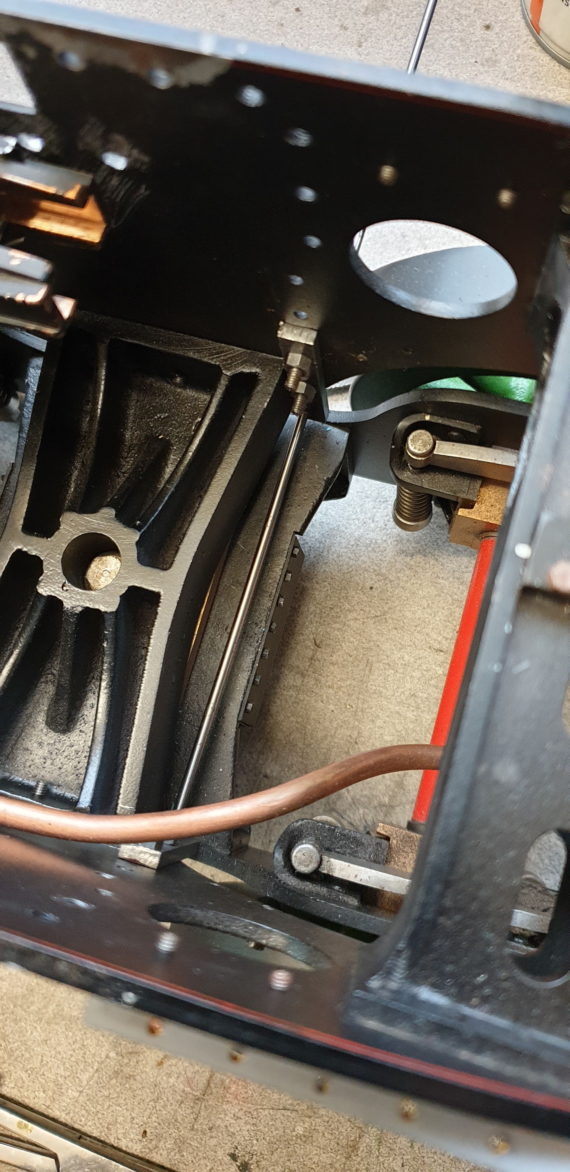
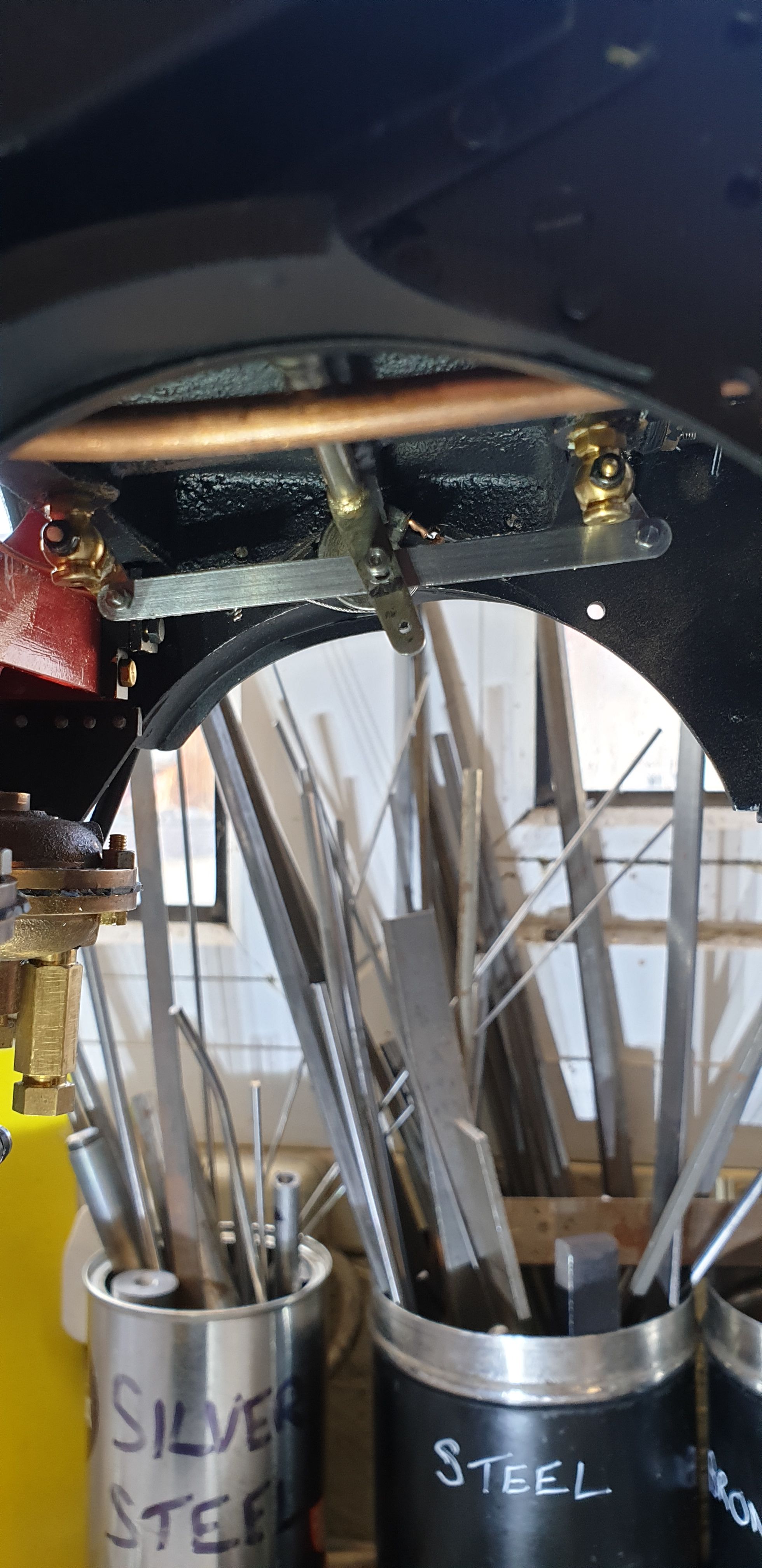
And here's the link mounted in place, I will use 10 BA bolts/nuts for this, using two nuts to lock together. The lower hole seen on the middle cylinder cross shaft arm is for the link that goes to the outside cylinder cross shaft arm. The copper pipe seen running across, is the main vacuum pipe going to the front buffer stand pipe. It's getting very crowded under here and fitting the 10 BA bolts wasn't easy. When I first fitted this link I found it was very stiff to close the draincocks, too stiff to be sure that this wouldn't become a problem in the future but was fine past the closed positioned. This was cured with me elongating the oval hole in the cross shaft hole a little as it wasn't long enough for the job in hand.
I have taken this video to give a little more info on the Bowden cable route and also to show the system working.
Next entry I'll hopefully cover the final parts of the draincock linkage to the outside cylinders. I have a few bits to do first, one of which is to do the lining on the cylinder cladding and then fit them along with their insulation. Of course, the outside cylinders will finally need to be fitted too.