
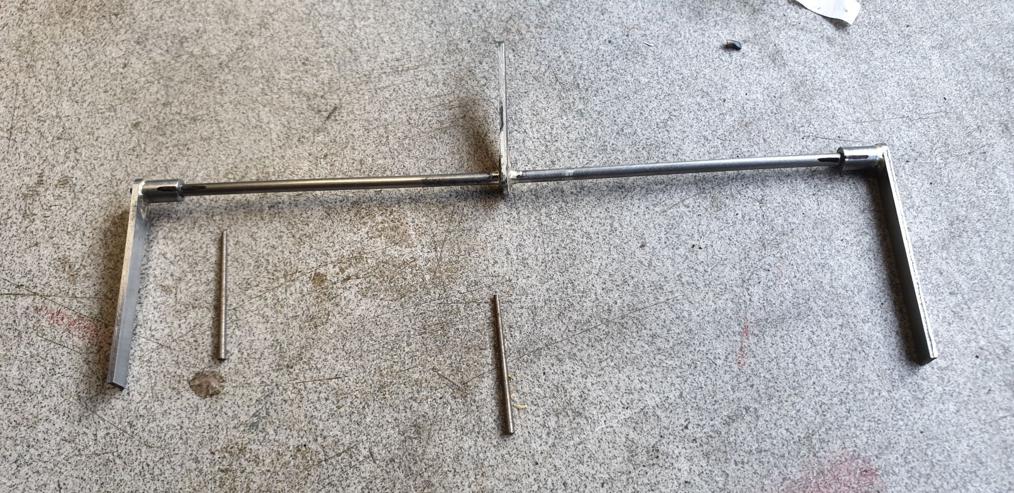
Last time I had made a start on the outside cylinder cross shaft and showed the trunnion positions. I then made the shaft, silver soldering it's arm in the middle and making the end arms to connect to the outside draincock linkage. Here's the shaft in an early stage, the arms will be bent to meet the draincock links and shaped to look something like the close up photo's shown of the prototype. I'll show more details on this as we progress. The arms will be secured with 1/16 taper pins.
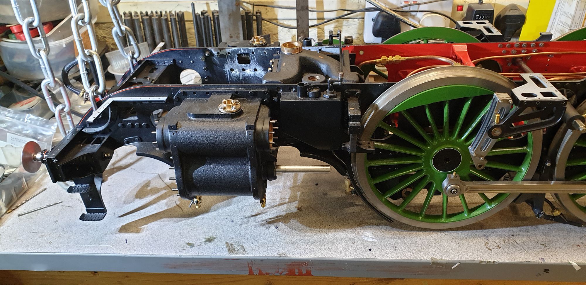
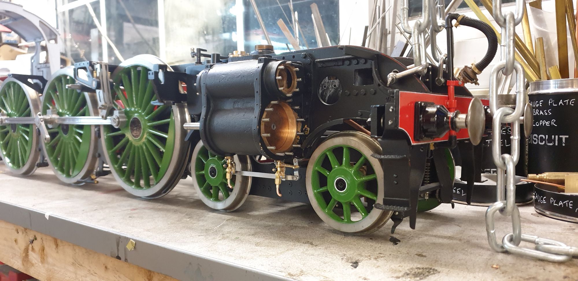
Before I could go any further with the draincocks I needed to fit the outside cylinders permanently to the frames. This took much longer than one would think, some of these 6BA bolts are very difficult to get too, not helped by the fact that I chose to fit studs for the piston covers. I found that for the bolts closest to the steam chest exhaust chambers I had to put the bolts in from inside the frames and secure with small size 6BA full nuts on the outside as there was no way of getting a bolt into the hole from the outside. This all took some time but I got there in the end, all bolts/nuts have had a coat of thread sealant applied to hopefully stop them from coming loose during running. Once I had done this all of the bolt heads were touched in with satin black paint to finish. This picture shows for the first time that 4472 now has all 3 of her cylinders fitted.
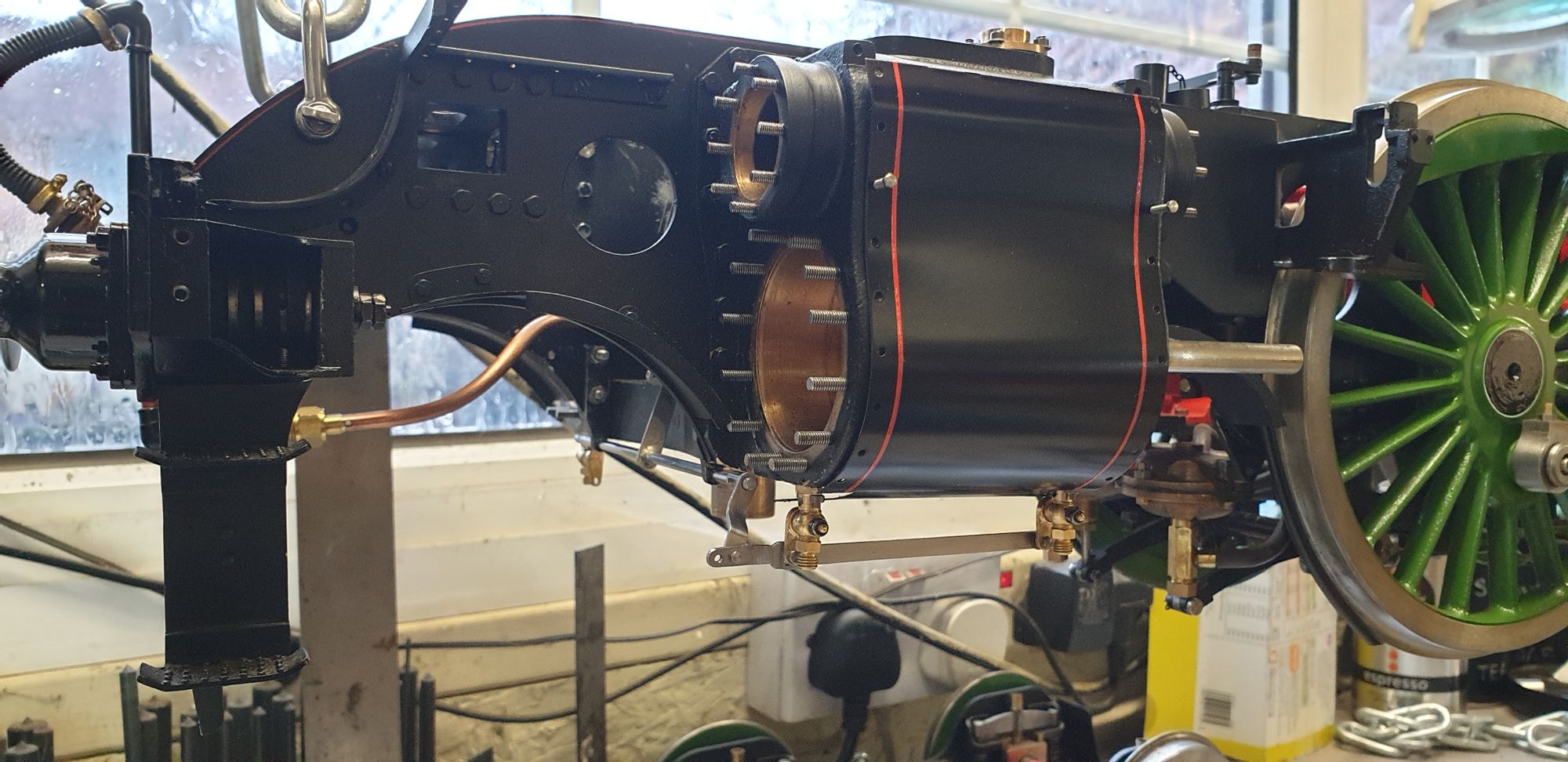
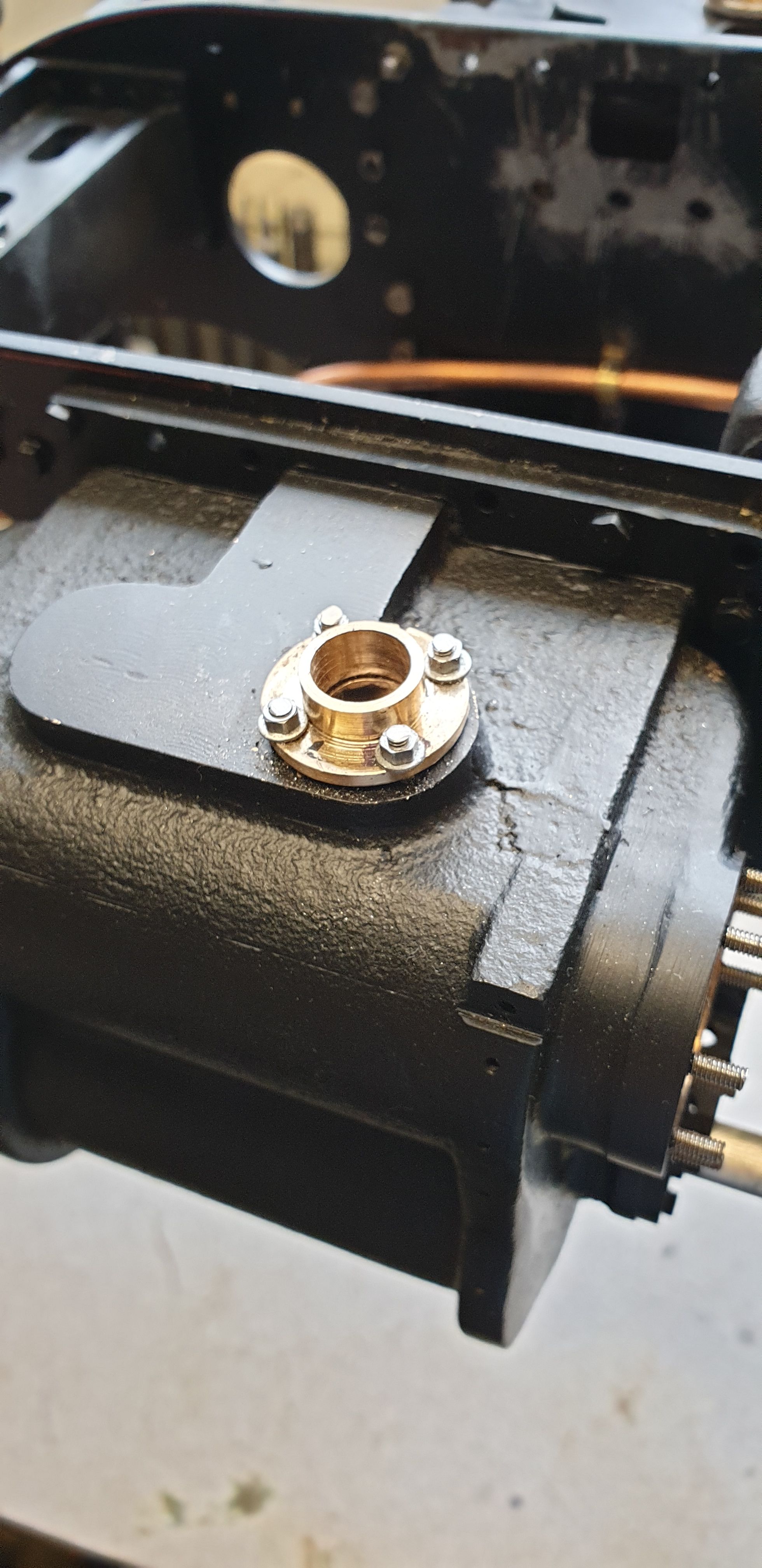
Before continuing with the draincocks I removed the main steam pipe flanges and cut and fitted 8 BA studding in place of the bolts. My reason for this was in reducing any risk of damage which might occur to the threads in the bronze cylinder with multiple screwing/unscrewing during future maintenance. A close up of one of the main pipe flanges, I'll make the pipes themselves later.
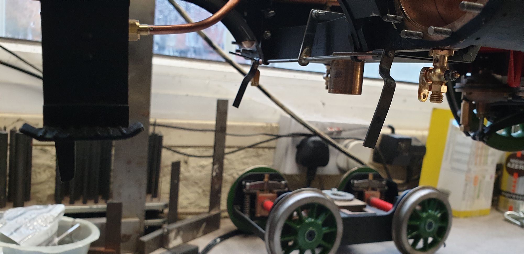
Next I moved back to getting on with the draincock linkage, here the cross shaft is temporarily fitted for me to fabricate the end arms so that they line up. Photos of the full size show me that the arm has a dogleg and that the pivot point for the link is below the draincock arm hole. To follow suit I have made my arms in a similar fashion but of course they are made to fit what's there and thus sizes will differ a little. You may note in the photo that I have made two short copper sleeves to fit between the arms and the trunnions. The reason for these is two fold, first they hold the arm central for the long link from the middle cylinder to connect but also they make it very easy to remove the cross shaft without needing to remove the trunnions too. Makes life much easier especially for when fabricating the end arms to fit. In this picture the arms are very much oversize and still need profiling. You can also see the taper pins that secure them still needing to be cut to length, I left that till last as it makes pulling them out to remove and then work on each arm much easier.
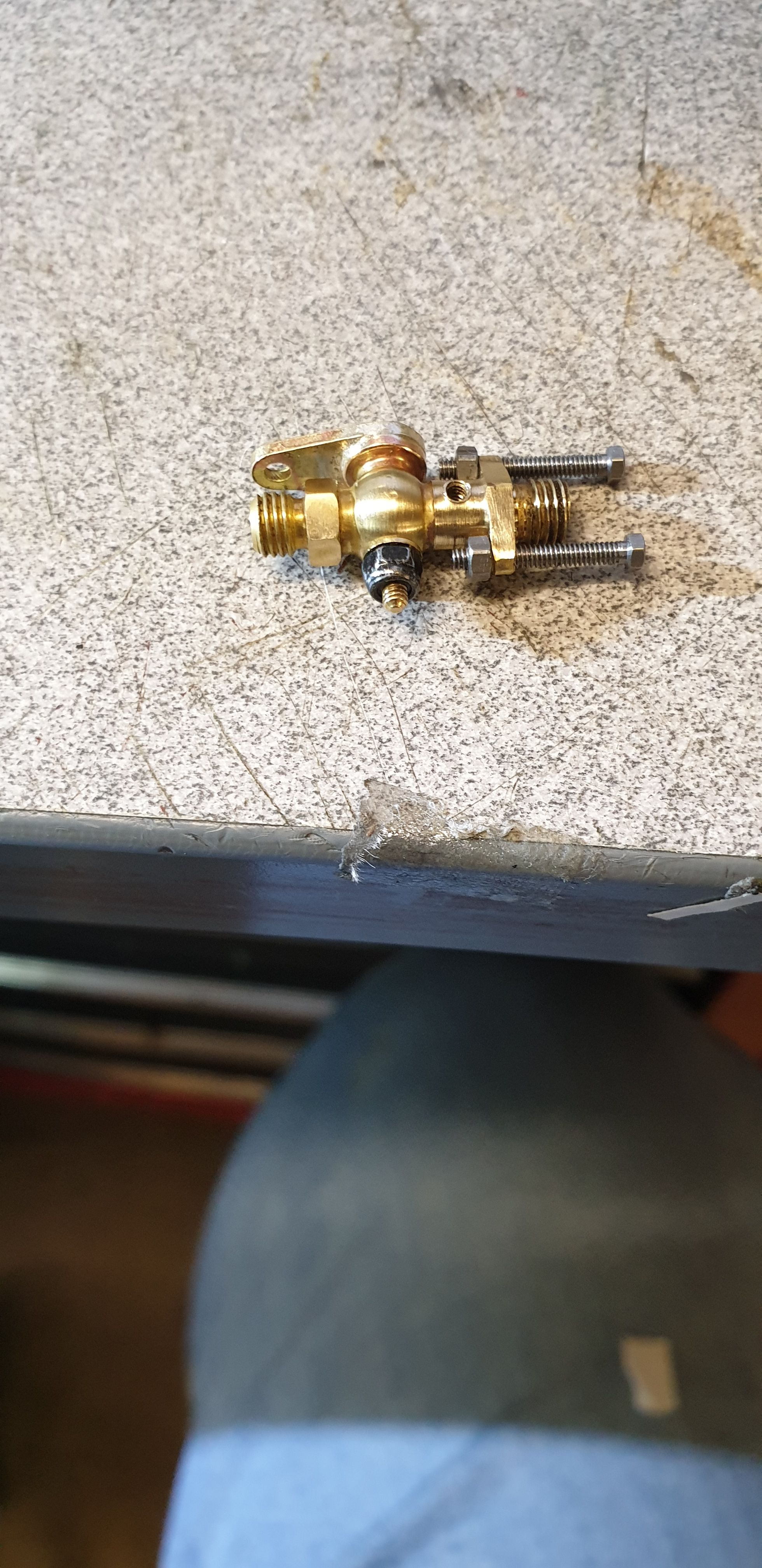
With the cross shaft and it's end arm blanks ready for the next stage I then needed to fit the draincocks to the cylinders properly. Before doing so I needed to fit the dummy studs/nuts that hold the relief valve body to the cylinder, here you can see one of the draincocks having had the dummy studs fitted awaiting the ends to be cut off. My approach here was to drill/tap the flange holes 10 BA, screw in a bolt and then screw on a nut, the nut was then locked against the flange and the end of the bolt cut off and filed flat, a little overscale when see alone but blend in nicely when fitted to the cylinders. I will probably leave the fitting of the relief valves until much later to reduce the risk of damaging them during the rest of the build. One thing that I did check before fitting the draincocks was that the cutouts in the cladding were large enough to allow me to fit the cladding with the draincocks in place, this was successful. I used Loctite 567 to seal the draincock threads.
Now when I got to this stage I did a 'U-turn' on the cross-shaft, I wasn't happy with it's rigidity and decided before I went any further to go for Don's suggested upgrade and have a 1/8 cross-shaft instead of the 3/32 one that I started with. When trying to build a scale model it will always be a case of compromise where needed, I decided that this was such a situation, for the simple reason that i wasn't happy with the small twist that was evident in the cross-shaft when operating the linkage.
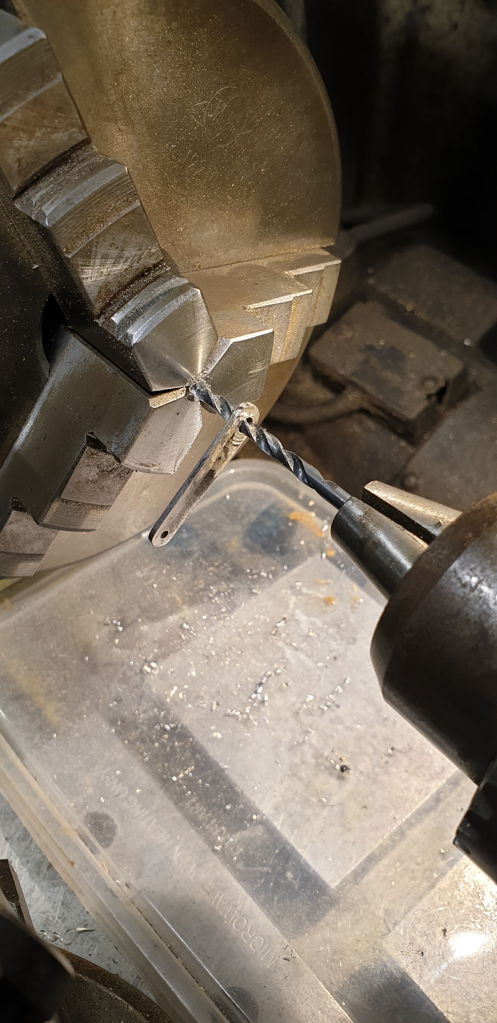
So, it was not back to the drawing board but the aim was in making use of some of the parts already made but this time to fit over the thicker shaft. There was more than enough metal on the 3 arms that fit onto the shaft, so my first job was to modify these to fit 1/8 bar. The ends were plain boring out from 3/32 to 1/8 on the lathe. The middle arm is silver soldered to the shaft so needs removing but rather than de-solder and then drill out I thought it better to cut one end of the shaft off, hold the other end in the 3 jaw and drill straight through, this ensured that the new hole was central and made the job very easy and quick. I'll just show the final picture of when the 1/8 drill detached the arm from the old shaft, I think you can get the idea of what else was done before this stage, ie cut the shaft, machine the rough edge flat, centre drill and then open up with the 1/8 drill bit.
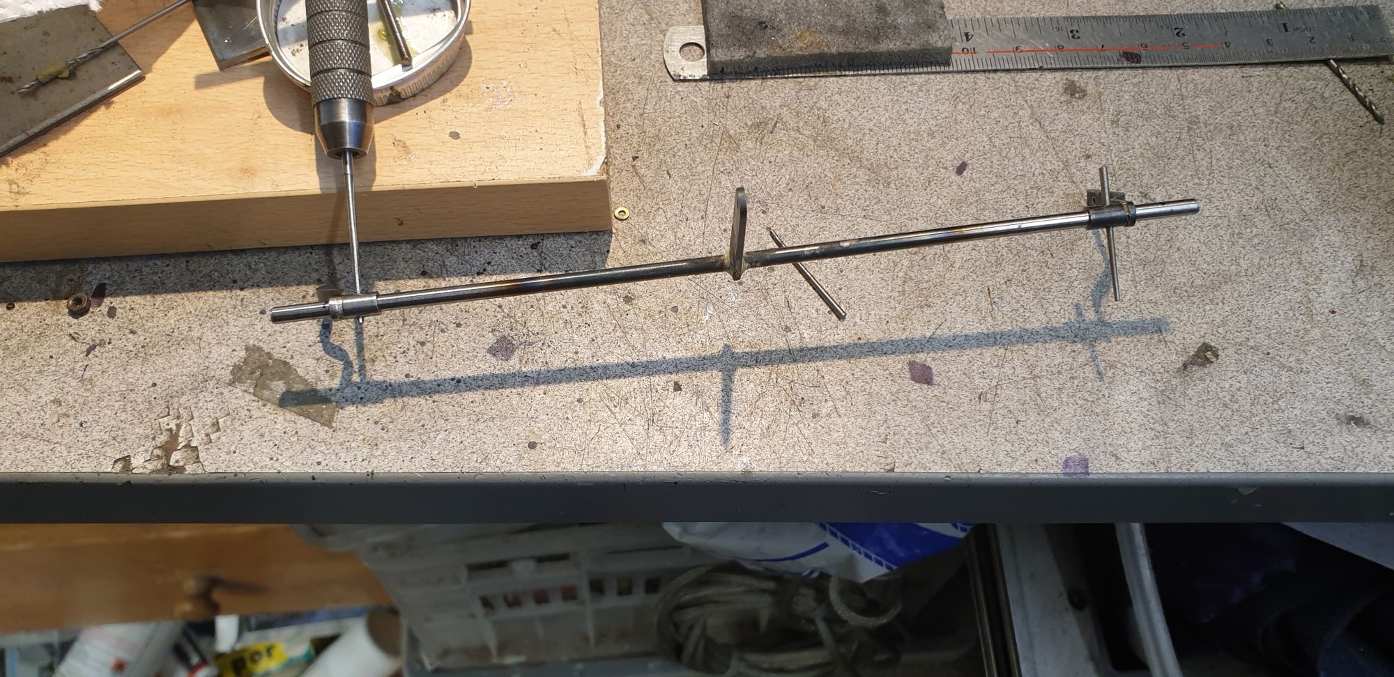
Here's the new shaft in the process of having the taper holes reamed with a 1/16 taper reamer, I lost my old one so had to order a new reamer from Tracy tools Friday afternoon, it arrived first thing Saturday morning, very impressed with the service. As can be seen the shaft is over length in this photo, cut later. One other thing to point out, during the trial and error stage of setting up the linkage to work smoothly, I found it better to clock the arms further in relation to the center arm, this was a simple task of refluxing and heating the arm and clocking it to where it worked best.
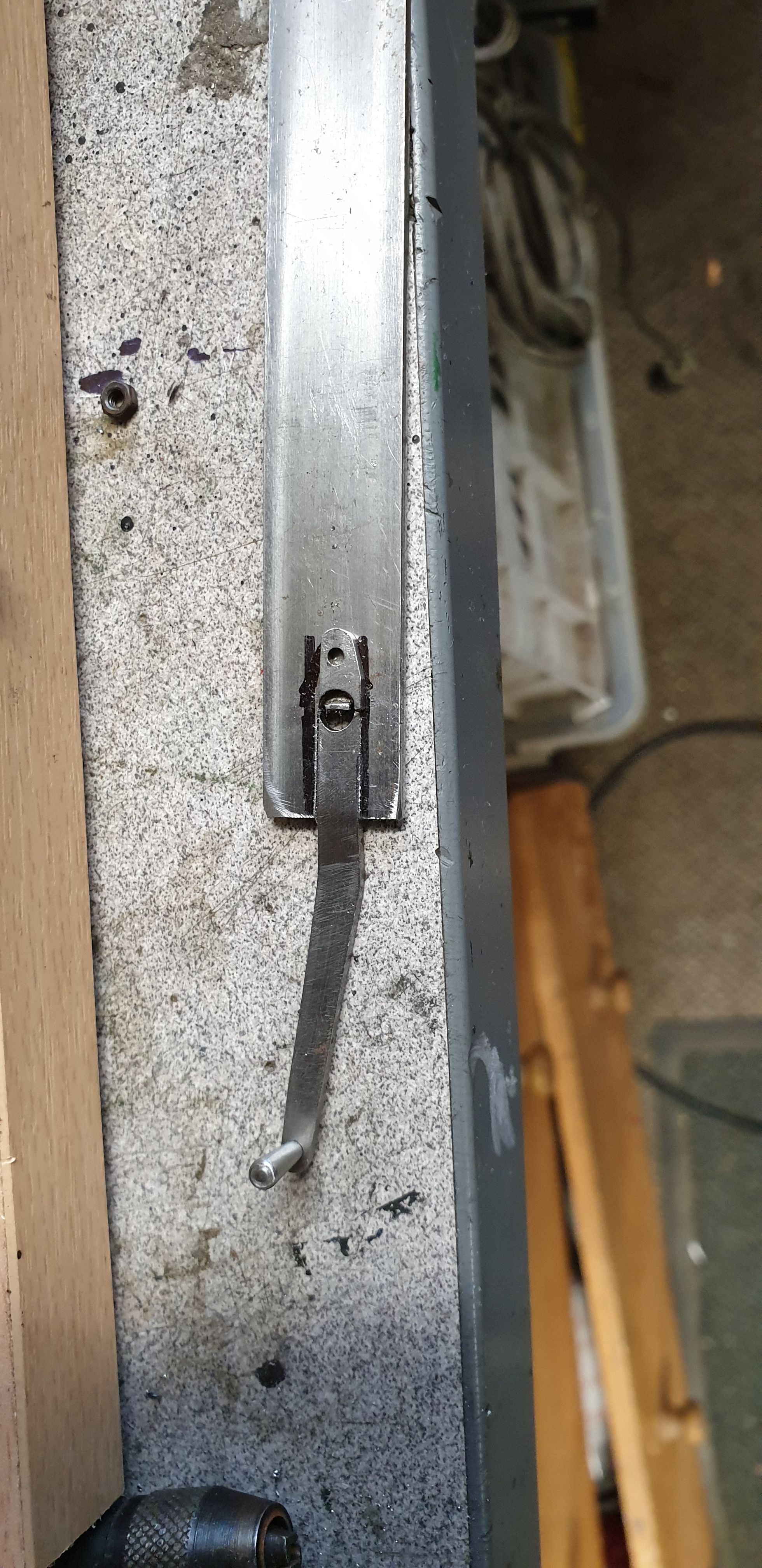
I made another change too, during the testing I found that the handle wasn't strong enough enough for the job in hand, this didn't surprise me as I had left next to no metal around the central 5/32 hole. Not wanting to remake the whole thing I got a piece of steel the same thickness from the offcut box and cut a slot in it for the arm to slide into, it was a very tight fit. The part of the arm below the 5/32 hole had snapped off and so to keep things in line, after the handle had been silver soldered into the slot in the steel offcut I loctite'd the broken part on top of the new steel as a template. I checked the drawing for the hole distances which was 7/32 and drilled the 1.8 mm hole for a 10 BA bolt to pass through in its correct position. Alas i forgot to take a photo of the finished arm but it's now much stronger than before and won't break again no matter how heavy handed I may get.
And this is where we are with the various parts assembled ready to test, as can be seen I have also found time to paint the cylinder cladding and line it with vermilion red. I have only held it here with two temporary 10 BA bolts, I have cut 38 of these bolts down to size, approx 3 mm long and have painted them and left to harden, when the cladding is fitted i'll also add insulation behind it for better heat retention. For now, I will remove the cladding and store it away with all of the other painted parts until ready for fitting. I think I've already mentioned, that I'll also leave the relief valves off for now too. The link across the draincocks to the control arm needs the end hole cut of and profiled, I was playing with various setups until happy with how the linkage/Bowden cable worked. If I remember I'll show this link in more detail when I do the other side as it's not just a straight link with 3 holes in it.

Lastly another video to better describe what I have been up too. As well as the draincock linkage I have also been busy catching up with small jobs that had been left till later, I'm very bad at doing that..:) These included removing another steel leave from the trailing axle spring in return for a Tufnel version in its place. I have modified this leave spring a number of times now as the loco weight increases and as I make adjustments to the springing, some may recall that when I first built these springs they could support more than 100lb in weight, far too much and resulted in the rear of the loco sitting higher than it should, something I had left until the boiler had been test fitted. I think that I have it right now. Other jobs involved making up 6 silver steel pins to connect the main axle spring buckle to the swivel pin on the bottom of the axle box, this had been held just with some small bolts/nuts until now which of course meant the axles weren't actually sprung as there was a lot of play in the joint, the new pins are tight fits into the relevant holes. Don noted and I have since had confirmed that there is a shield that goes around these pins to help hold them in place, I still need to look at this, currently I'm thinking of using some shaped spring steel which can be a 'snap' fit over the swivel pin, I'll look at this later, yes another of those to do list jobs. While working on the springs I also took a closer look at the chassis running height and it's lever which as already pointed out was sitting high at the rear. The fornt was also sitting low and so I have turned up a washer to fit between bogie yoke and bogie, in fact I now have two, not as many as full size though, I recall seeing more than this in photos.
Ok... enough rambling, here's the video..
I have now fabricated the R/H draincock linkage and made the drop pipes, I'll shorten these a little later to be closer to the prototype, the nuts are a little large which adds to the oversized look so I'll also shorten these. I'm pleased with how they look compared to full size, you'll note that I have only placed one relief valve roughly in position for effect. I'll leave these off until final assembly as they can't be fitted until the cladding is in place. I may also thin down the main link between the two draincocks to be closer to scale, if so I'll only do this on the outside cylinders, the middle was deliberately made larger as it's not as easily accessible once the model is completed and can't be seen.
I am also going to add ferrules to the cab end of the Bowden cable (the front is already held by ferrules) to remove the possibility of the cable slipping while operating all three of the cylinder draincocks, this is something that I noted during setting up and ironing out restricted areas until it operated smoothly, better safe than sorry. On this note, I changed one of the cables as it had become a little frayed on the cab end, this was a worthwhile exercise as it proved that the cables can be easily changed in service.
So on final assembly, the cables will be set and held by the two 10 BA bolts and then have ferrules attached to ensure the cables can't slip. I won't do this yet as the cab needs to be removed again which means disassembling the handle which may change the tautness of the cables, so this will be another of those many final jobs to be done. A picture to show how things are looking....
With the adjustments to the rear cartazzi springing and the bogie spacing the chassis is now nearly sitting level (down a fraction at the front) and a little high which bodes well for when the boiler is fitted.