Continuing with the various parts to fit to the cylinders, this time we have the 6 relief valves. I have followed Don's overall dimensions but added extra detail and made them fully working and easily adjustable to what I feel is perhaps close to how the full size work. I have no works drawings for these so the innards are to my own design.
I'll begin with a picture of the prototype, this is yet another of those pictures which I took at York in 2016. Hopefully me representation will look close to this although I have cheated a little on the end cap leaving off the thin steel plate in place with a bronze piece, I may add the thin steel plate later, we'll see.
I'll also show Don's drawing which is pretty good and his dimensions certainly seem to work although it seems to have left off the holed base? something I discovered later. I decided to ignore this as it's hidden under the cover and wouldn't work with the design in hand. Also, Don doesn't show or mention the small tabs with the bolts through them, probably to further simplify the part in hand?
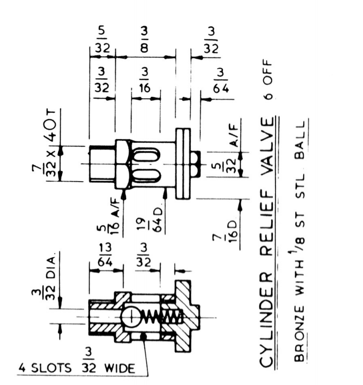
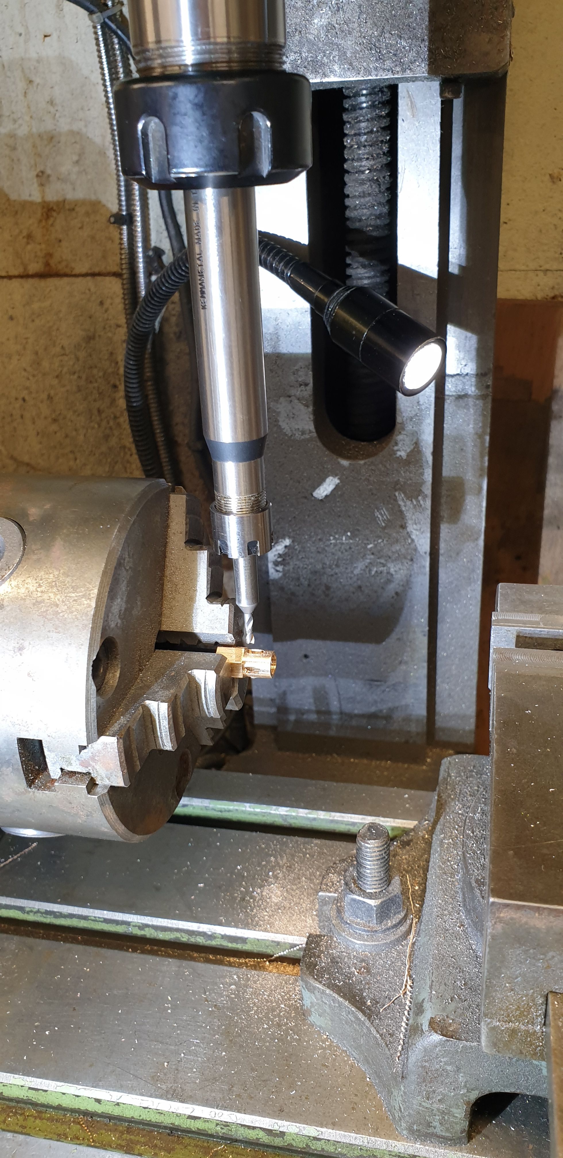
I haven't taken pictures of the turning operations which is all basic stuff, but will describe how I tackled the body section. The part begins life as some 7/16 bronze hex, Don starts at the 7/32 x 40 threaded end and then fits that to an adaptor held in the chuck, similar to how I did the draincocks. I started the other end, turning down the middle section to 19/64, drilling the centre at 2.3 mm, deep enough so that when parted the hole was right through and then machined the chamber using a 3/16 end mill. Last operation this end was to cut a 7/32 x 40 thread into the chamber for me to thread the end caps when ready. Don makes no mention of what he did here, the drawing looks like there's a short thread but no note of such in his words. I then parted off the body and moved on to the next body from the length of hex stick. I continued until I had all 6 bodies. At this point I then moved over to the rotary table and tackled the 4 equidistant 3/32 x 3/16 slots. Don's drawing is misleading here as his drawing does not show equidistant slots unless perhaps there are more than 4?, there are only 4 on the prototype and thus perhaps just an error in how they are drawn? I noted from the photo of the prototype the orientation of the slots, that being two on the flat section of the hex with the other two being on the corner. This can be seen in the photo above but not on the drawing which as pointed out, is incorrect. Here's my setup on the rotary table, using an ER11 collet chuck held within an ER25 collet chuck to give me the clearance required to get close up to the hex. Note, that each part was parted overlength to give me more to hold on to. This worked out surprisingly well.
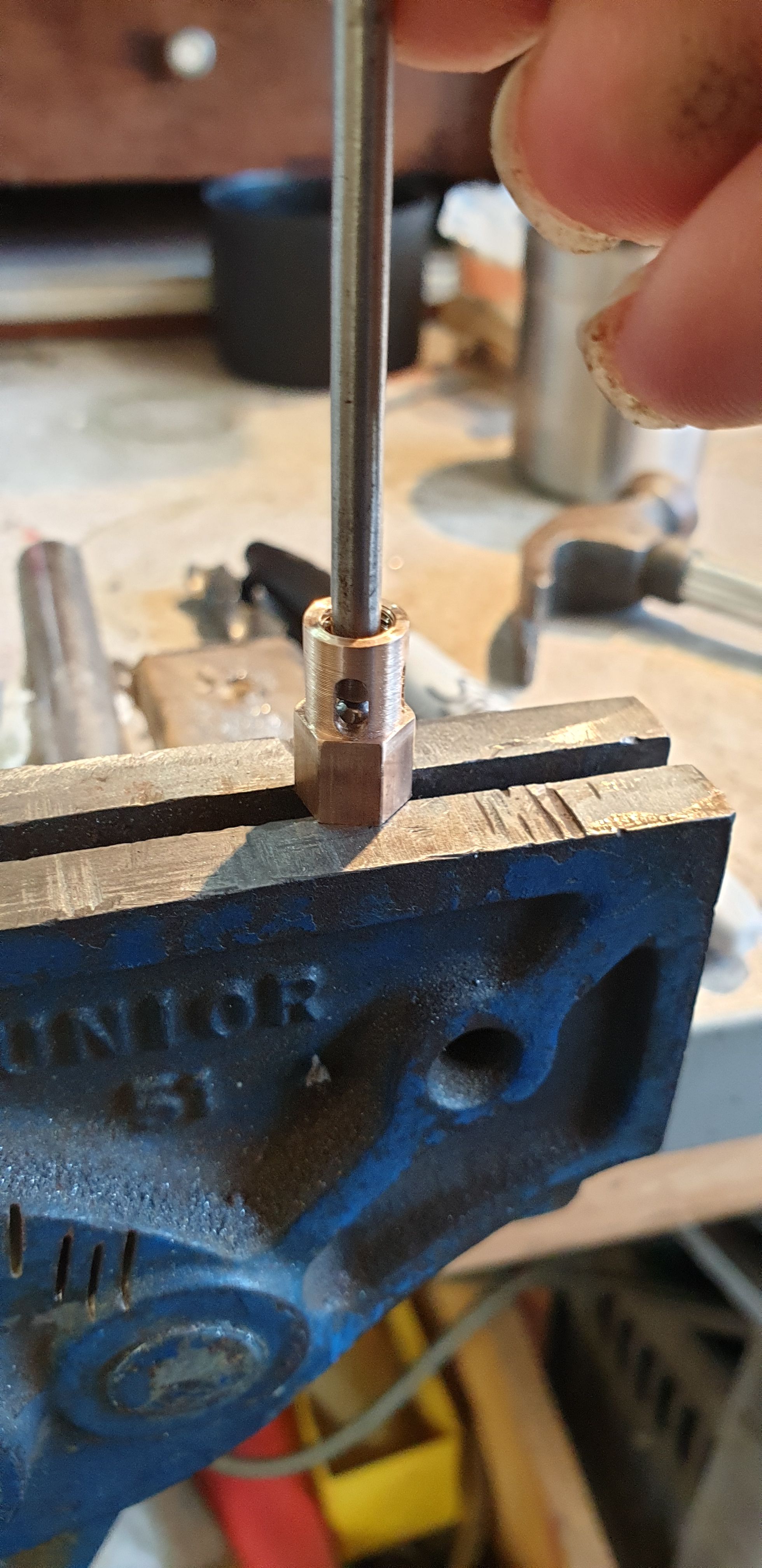
Before returning to the lathe to machine the opposite end I first seated the stainless ball using a sacrificial 5/32 ball for the job. Don shows a 1/8 ball with a very much undersized stainless spring, in fact he adds that if the spring bends during operation to fit a short length of stainless bar through the end cap to help keep it straight? Well, I have gone a different route, first off, that 1/8 spring is far to narrow when compared to full size where it's clear to see that it's a snug fit within the body? Therefore, as stated the ball has been increased to 5/32 and used a larger sized stainless spring to look more the part. More on this later, here's a picture of one of the bodies having it's seat applied via the traditional sharp tap against a sacrificial ball of the required size. Of course, I had to use a drift to get access to the ball. As I did this to each body I checked that the ball sealed by trying to blow and suck through it, I couldn't get it to leak, we shall see how it does under 110 PSI?
Each body in turn was returned to the lathe to have the hex section reduced to 3/32 in length and the 7/32 x 40 threaded spigot cut at 5/32 length . Here are the 6 bodies with one of them screwed into a cylinder cover. I did mess up on one body, not enough to effect it's operation but I did manage to mark it when not holding it properly in the chuck, well to be honest I forgot to tighten it fully...Don't worry, it won't be seen, this valve is now consigned to be fitted to the middle cylinder. I next took a little of each threaded length so that it didn't stick proud of the cover internally. (please forgive the quality)
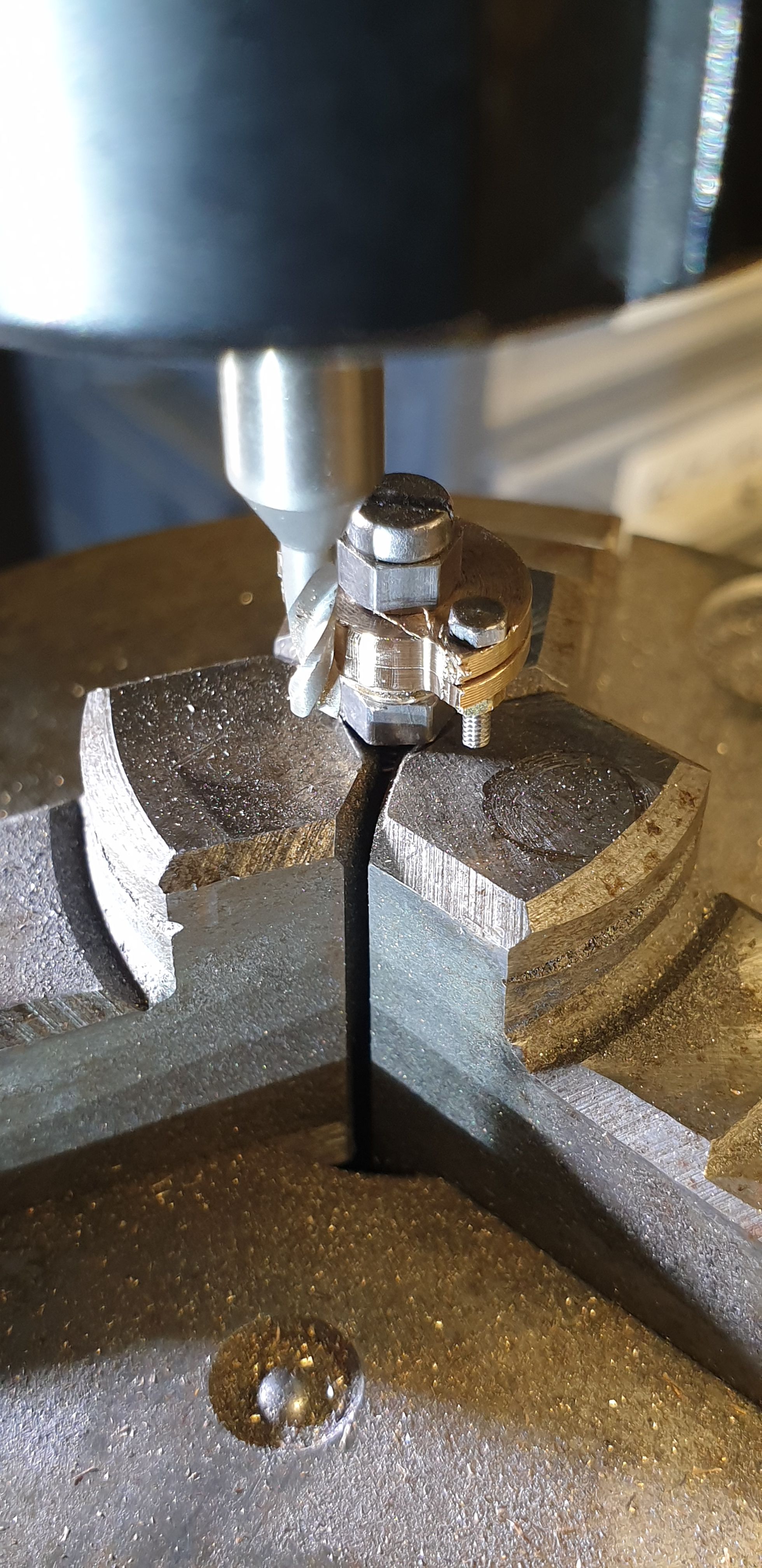
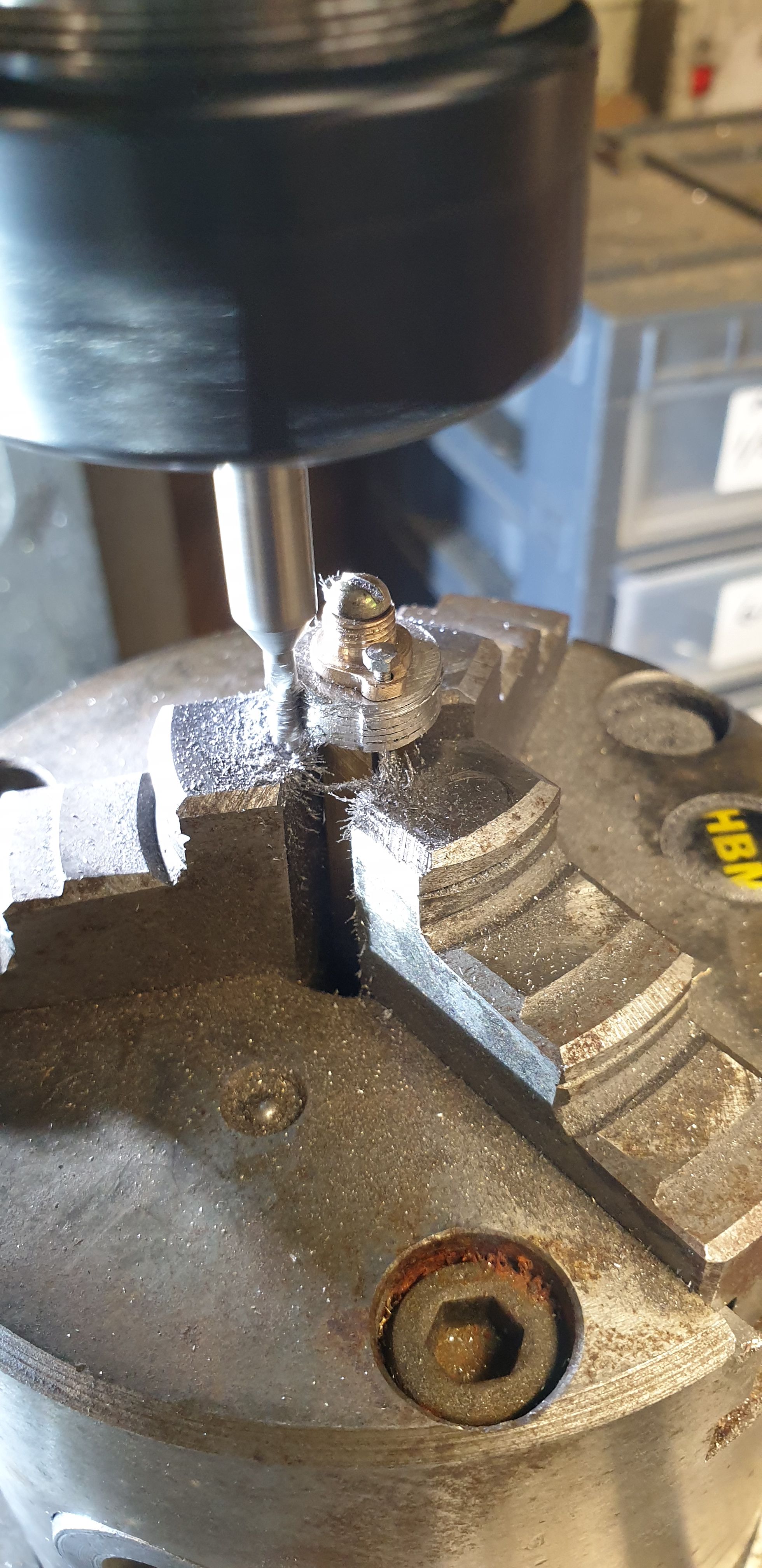
I only have one picture for the end cap construction which shows the cab being profiled on the rotary table. I'll explain what's going on after this picture. BTW, that massive bolt in this zoomed in picture is a 6 BA cheesehead, should give an idea of just how small these parts really are.
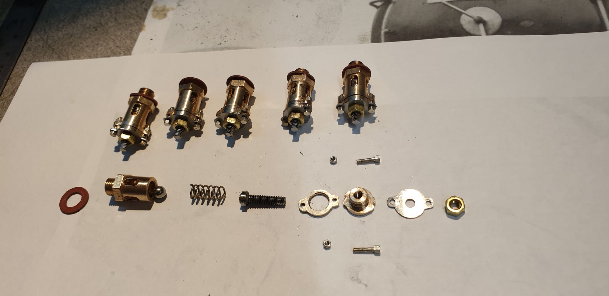
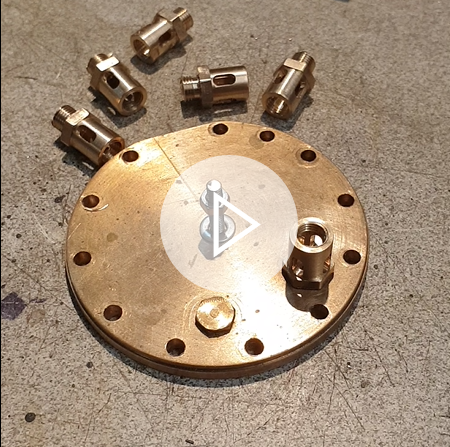
Ok, so a little more on what's going on and on my design for making these easily adjustable. I took this picture during assembling/finishing the 'kit of parts' which shows the caps and the internals. First thing to state is that I took the decision to make the body without the end flange to simplify the body, same as Don has drawn. So the cap was going to include the body flange, now when machining the covers I had two things to consider, first was that I couldn't get the die close enough to the flange for a tight seal against the body and also that in making the cap as one piece, once profiled with the tabs I then needed to consider how I was going to scribe a line around its middle to represent the joint between cap and body? I found a way to kill both birds with one stone, I'd make the caps in two parts, this would give me the join line and if I increased the hole through the inner section, it could slide over the part that wasn't threaded... I hope that makes sense, the final picture at the end of this entry should help with this. This next picture though shows that the two valves closest to camera are nearly there with there caps fitted with the others just needing to have the tabs filed to shape. Now these caps are drilled/tapped 6 BA for the internal adjuster to screw into. You can see these in their early stages on the right of the picture, the left end has a machined step cap for the end of the spring to engage with. The idea being that this part screws in from the inside before the cap is fitted, the large brass nut (as seen in full size) screws on from the outside of the cap leaving a length of thread extended. I can then release the nut and thread in the part to increase/decrease pressure on the spring to adjust accordingly. Once all have been set at the required pressure I will cut the threads off just leaving enough to get hold off for any further adjustment that may be required in the future. I'll probably file two flats on this to get a better grip. The end result should be a relief valve which looks the part with only the short rod sticking out of the nut to say different.
At this stage I took another look at the 'steel plates' As stated i was going to leave these off but what I hadn't realised at the time was that there is a void between plate and flange. So, if I was going to fit the plates I would need to remove the tabs on the cap keeping those on the collar behind to give the overall impression of full size. The problem here would be that once the tabs had been removed I wouldn't be able to fully tighten the end caps without marking them, I could have silver soldered the collar to the cap but didn't want to involve heat at this late stage of the game, especially with the threads being so close. I therefore turned off the tabs but leaving just a short section with part of the bolt hole still evident so that i can tighten with a C spanner that I'll make later. The short section of tab won't really be noticeable as the bolt sits above it, this will become clearer once I have finished the valves. To make the plates I used some 0.5 mm stainless steel sheet, actually it's a left over from a new cooker hood ducting fitted last year. I kept it to have a go at spinning the cylinder covers, we shall see how that works out later. I began with roughing them out using one of the caps as a template, as can e seen I have bonded 6 small sections of plate together for machining, for this I used a Loctite retainer.
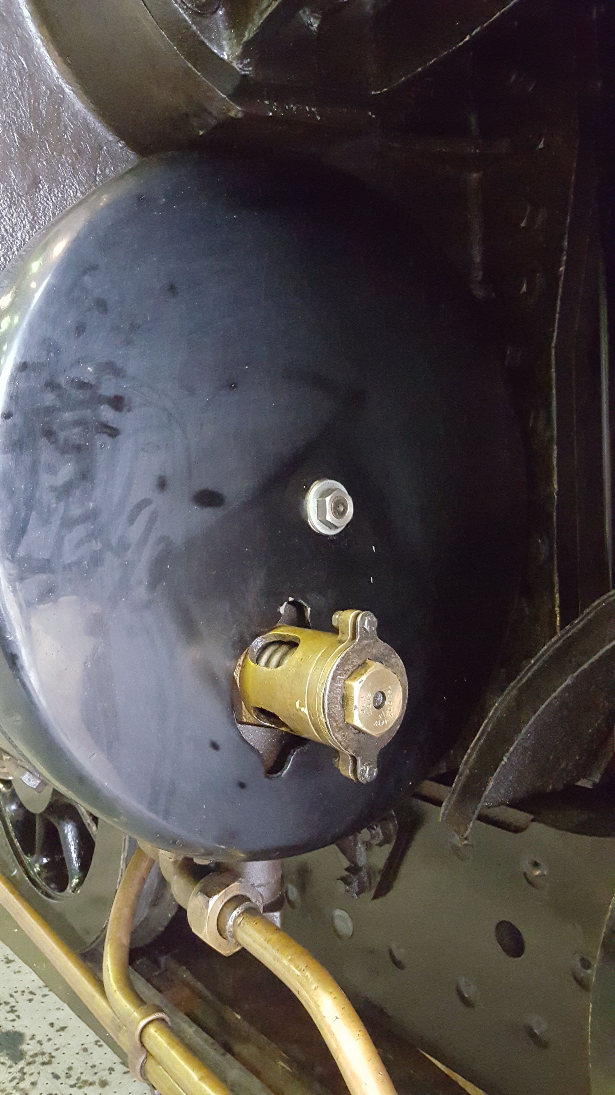
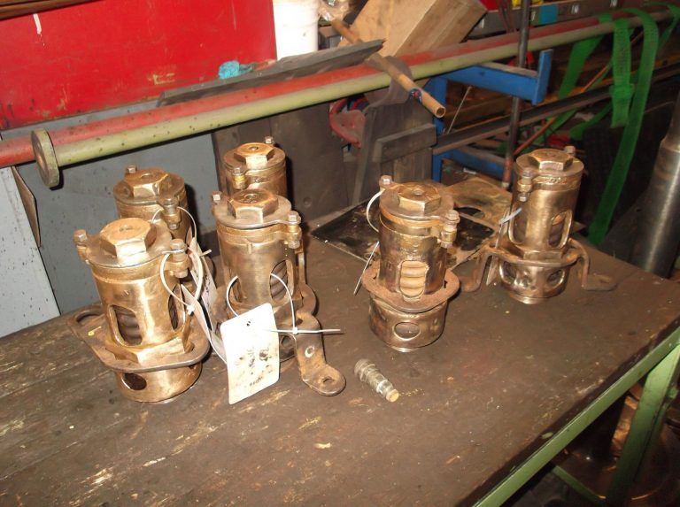
Here is a picture of the valves fitted to SNG to show what I'm trying to achieve, as stated earlier the lower section is not on the model and would not be seen with the cover fitted. Picture is from the SNG overhaul pages.
And here's another showing that these valves are set the same way in full size as in miniature.
And here's a video showing one of my own valves being set, it's a bit long winded as i took a few goes to get the pressure right, the other 5 were much quicker. I actually took a video prior to this one but had forgotten to fit a washer between valve and pump adaptor so i scrubbed that one. This one is basically the same thing. I think I best invest in a tripod for the phone if I'm going to keep doing these videos..:)
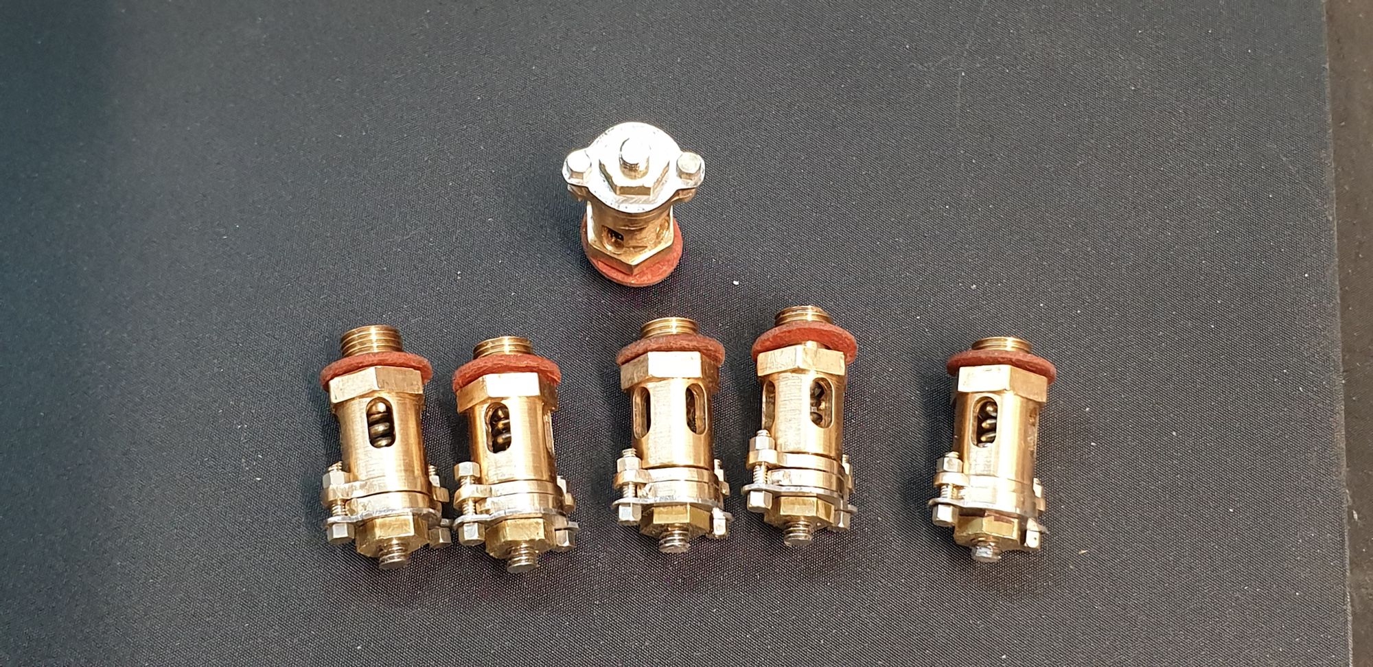
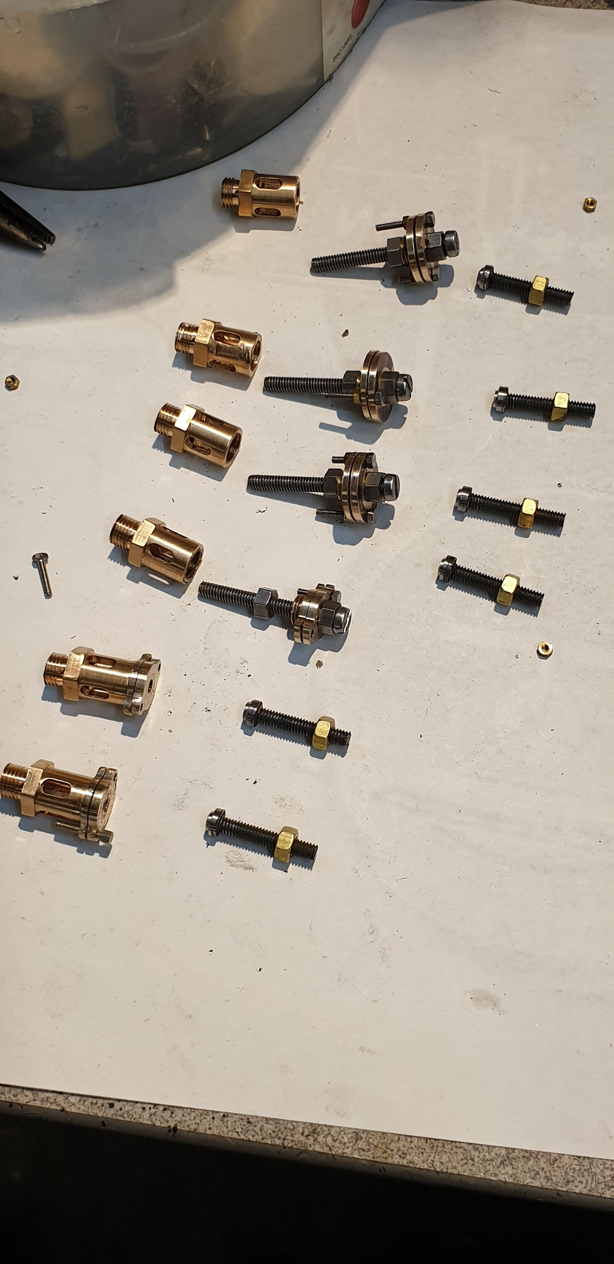
Last picture for this entry shows 5 of the valves now assembled and set at 110 PSI, I have left one disassembled to show it's 'sum of parts'. Note that I have shortened the adjusting screw and filed some flat on them for a 10BA spanner to fit. I will probably make these smaller to tidy them up as they seem more than strong enough for adjusting, much easier than the video might suggest using just pliers. I think the parts are self explanatory, the small bolts/nuts are 1.4 mm. I will recheck the valves before final fitting, I left one at 110 PSI setting for an hour without any pressure loss, another had a slight weep and lost about 5 PSI.

In the next entry I hope to fit the 3 rear relief valves and also the upper sliding bars, I have a number of bolts and castellated nuts to make for these first.
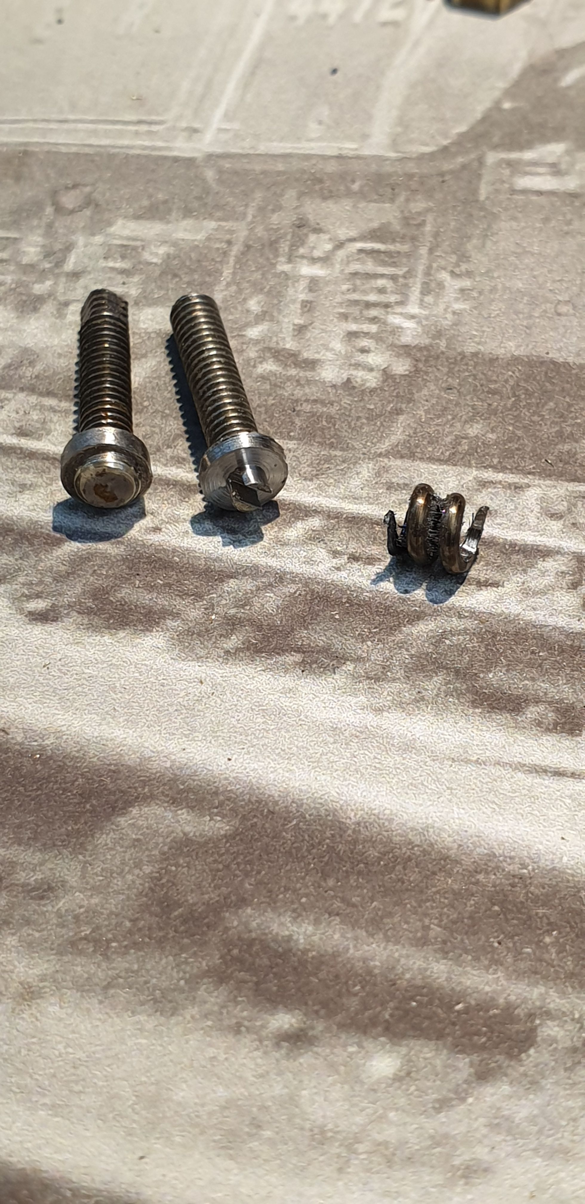
Edit: An addition on the valves, I noted before that i would revisit the adjusting screws to shorten them a little and make them look closer to the prototype. This I have done, a few things have changed, The brass nut has now been machined from larger HEX bar and reduced in height, I have changed the adjusting screws, for these i have used stainless cheesehead screws which have had their heads machined down in dia and i have also reduced the thickness of the end cap that the springs engage with. I have also changed the springs to shorter and thicker wire size, increasing wire from 0.5 mm to 1 mm. I did this as I found that after a long period of holding pressure that the spring would weaken a little, the new spring is much stronger.
Here's a picture of the new adjuster screw vs the old, new being on the right, one of the new springs is also in view.
And a picture showing all 6 re-assembled and tested, I am much happier with this set-up.