
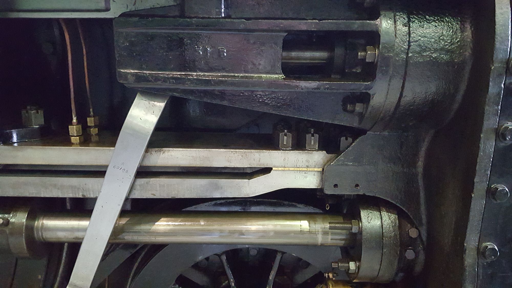
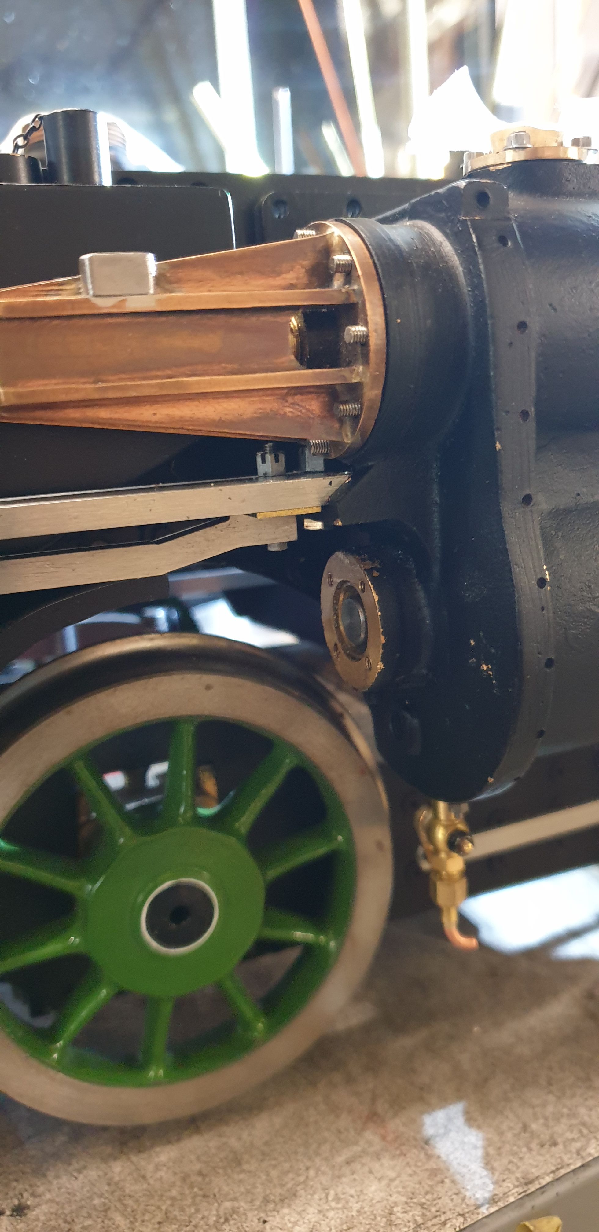
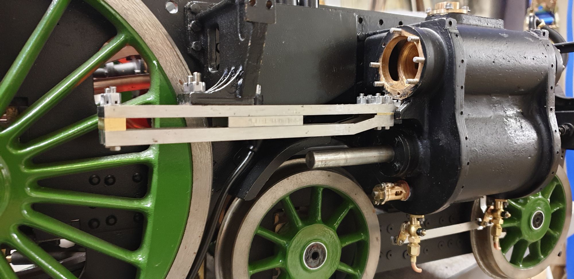
Most of the parts for the slide bars were made some time ago and have already been covered, this entry is the final stages and fitting to the chassis. Before I could do this I had a few castellated nuts to make in two different sizes. Now if following the drawing these are for 6BA bolts, I wasn't happy with the fit in the bars, that is there was a little movement even though the holes were drilled according to drawing. I have therefore increased the bolt size to 3mm, I had to open the holes a little but could now make them a close fit for the stainless steel bolts that I have selected. As for the nut hex sizes, I have chosen those that look close to the prototype, talking of which, here's a couple of close up photos which I took at York 2016. The first the 6 bolts/nuts at the front, two to hold the top bar to the cylinder and 4 slightly smaller bolts to hold the two lower bars to the top bar. Note how close the valve cover is to the castellated nuts and also the small step in the top bar for clearance of the cylinder mounting nuts, something that is not on Don's drawing and as you'll see when we get to it, something that is required on the model too.
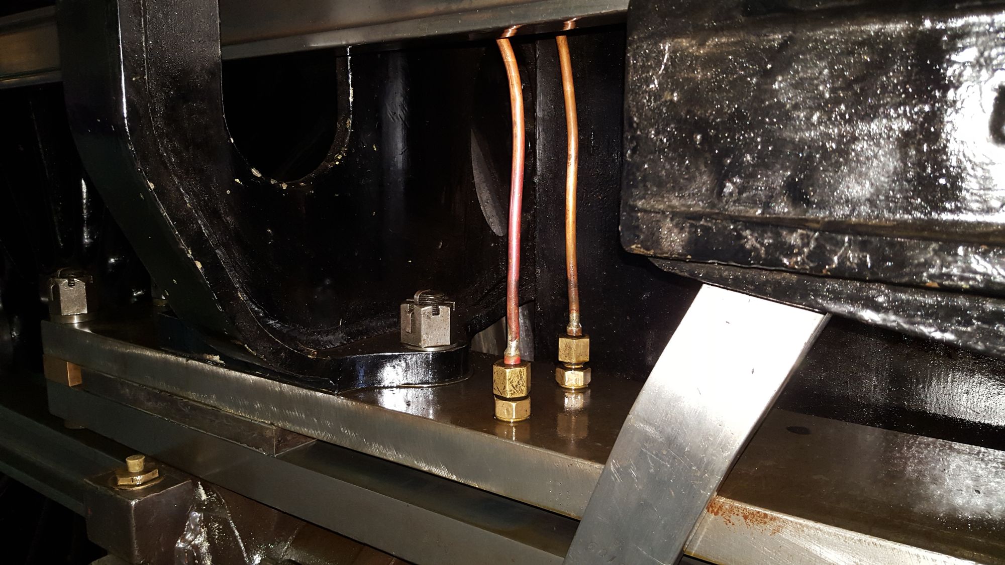
This picture shows the bolts that attach the rear of the slide bar to the outside motion bracket. There are 3 bolts for the motion bracket and two smaller bolts at the very rear to hold the lower bars. Something else to note is the oil feeds, I will probably have two feeds like this but they will attach to a cross piece oil pot that screws into a central 5/32 x 40T hole, so there will be the one oil hole in the top bar but it will look close to the prototype in general, this will be covered much later.
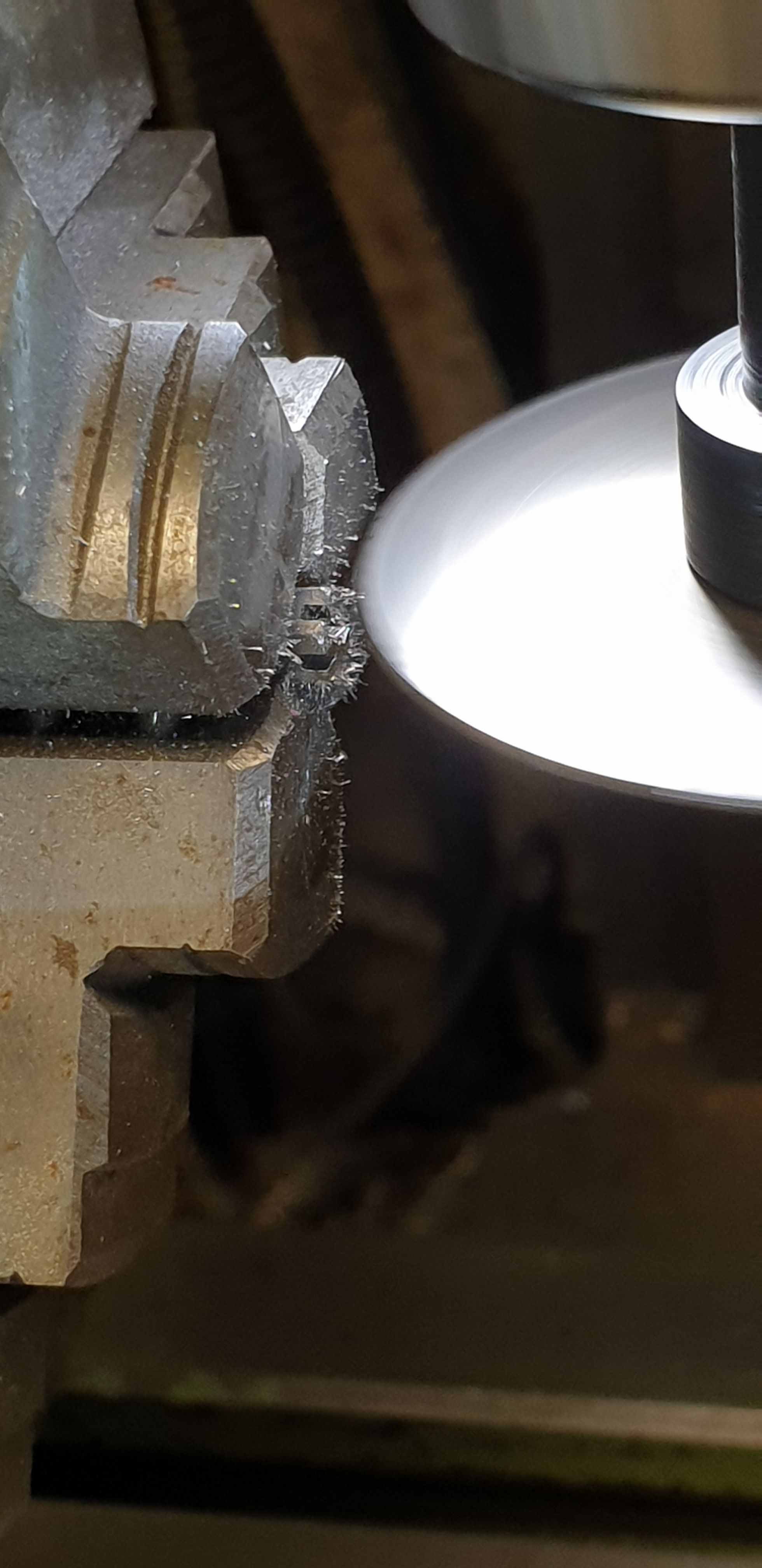
Ok, so those pesky nuts, to begin with these were basic turning on the lathe, as stated I have used two different size hex bar and one is drilled/tapped 3 mm and the other is 8BA. As for the length of each nut, I judged this from the photo's although also considering that I need to fit the things. One nut I later modified, again, this will become clear soon. With the nut blanks ready I then used a slit saw to form the castellation, as the nuts were all cut to length first this was a little tricky but still doable. To get each nut square in the chuck I used a small bolt to help align with the centre of the chuck, once the jaws were touching I checked that each nut could be slide in and out and looked parallel before tightening and cutting, simple but it worked. The picture shows one of the smaller nuts being aligned in the rotary table chuck.
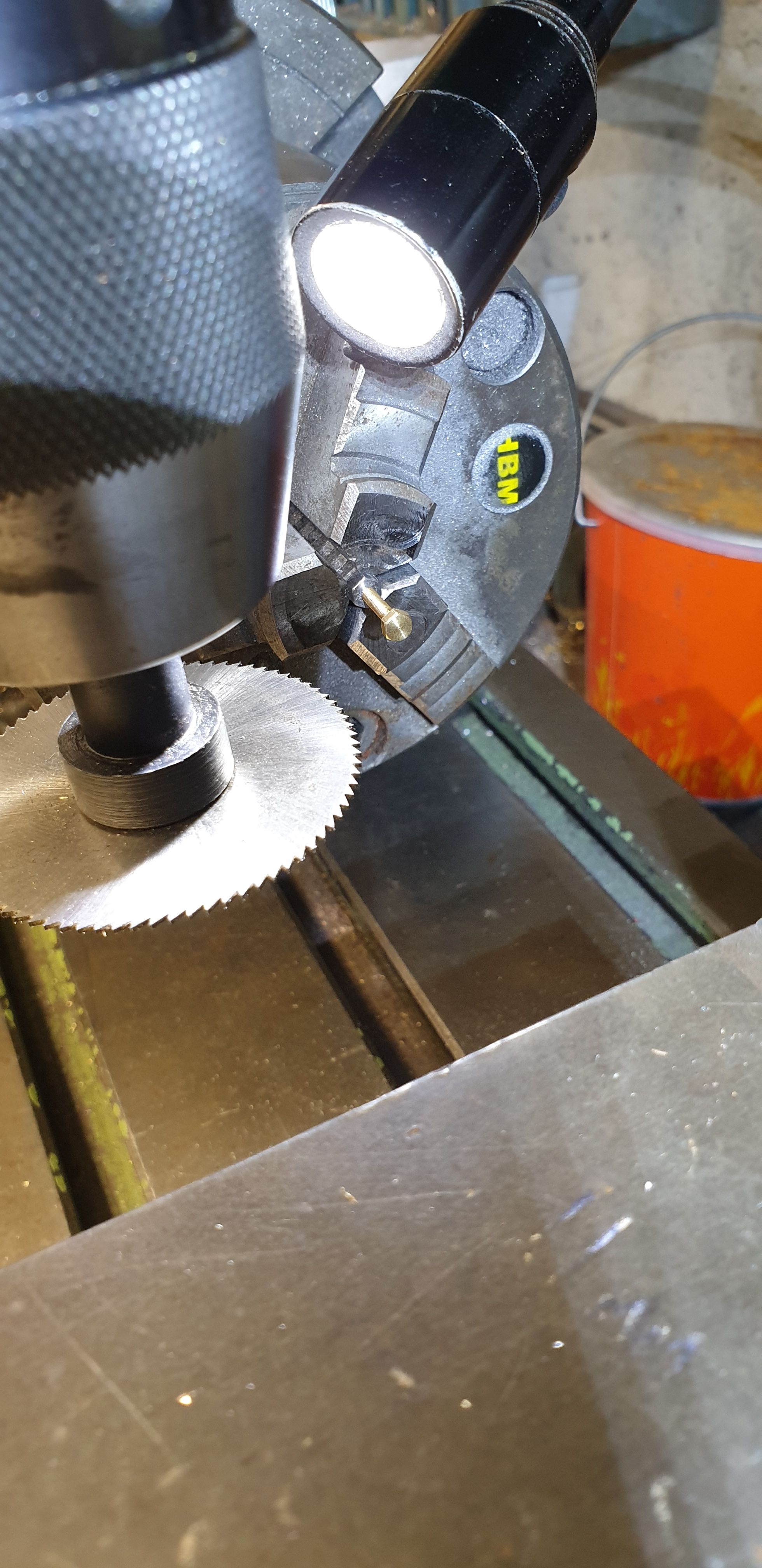
Before cutting I set the chuck so that when at zero on the dial the hex was upright in the jaws, that is the points of the hex were top and bottom giving me the flat edge AF to cut. Once happy that the disk was central it was a simple 3 cuts at 60 degree intervals to achieve the castellation.
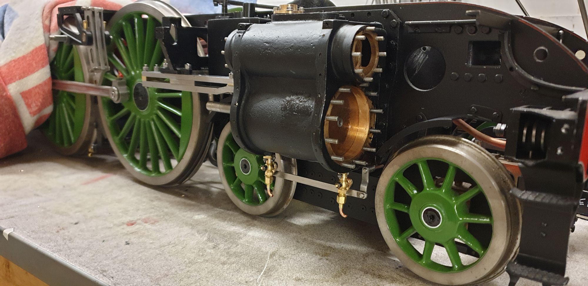
On to fitting the slide bars, here is the middle cylinder which was an easy job in comparison to the outside cylinders, actually, I still have the left hand slide bar to fit but all of the parts are made and I should get in done in the next couple of days.
Changes made were of course the holes being opened up to 3 mm, in this case though, only the rear hole. For the front two they have been opened up to 4 mm and a 4 mm thread has been tapped into the cylinder mounting lug. This makes life much easier, note also that I have deviated away from scale bolts here and used 4 mm button head hex with the heads turned down a little. Ok, not prototypical but it does make life easier or perhaps even possible to work on this easier in the future.
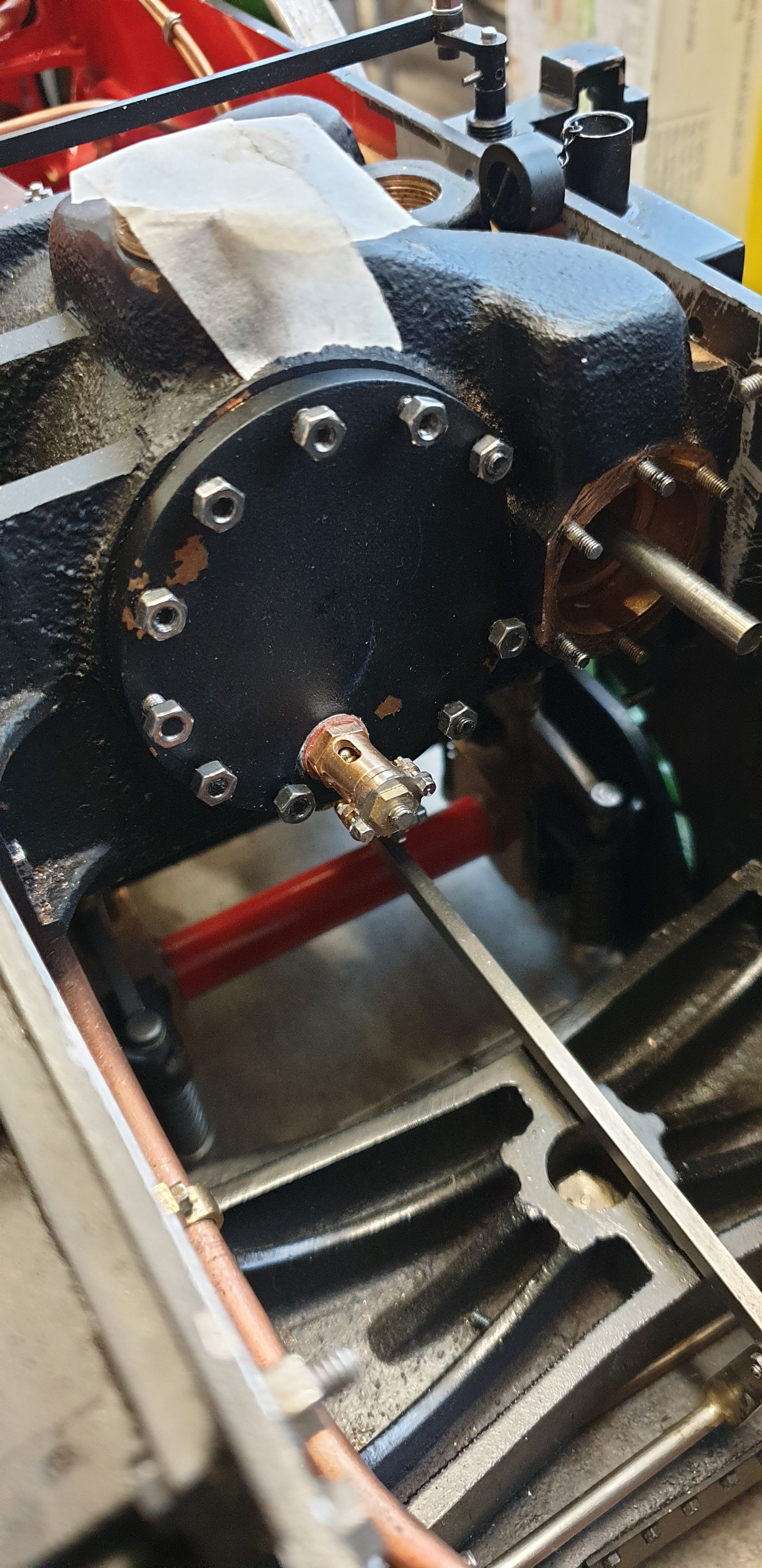
And here the first relief valve is fitted, in this case the rear valve for the middle cylinder, yes you can just about see it hidden in the depths of the frames.
While at it I also fitted the front valve, the cover won't be properly fitted until the pistons are connected to the crossheads/connecting rods and the stroke can be checked.
Now for the fun and games, fitting this outside slide bar took time, a lot of it, the joys of building to scale...:)
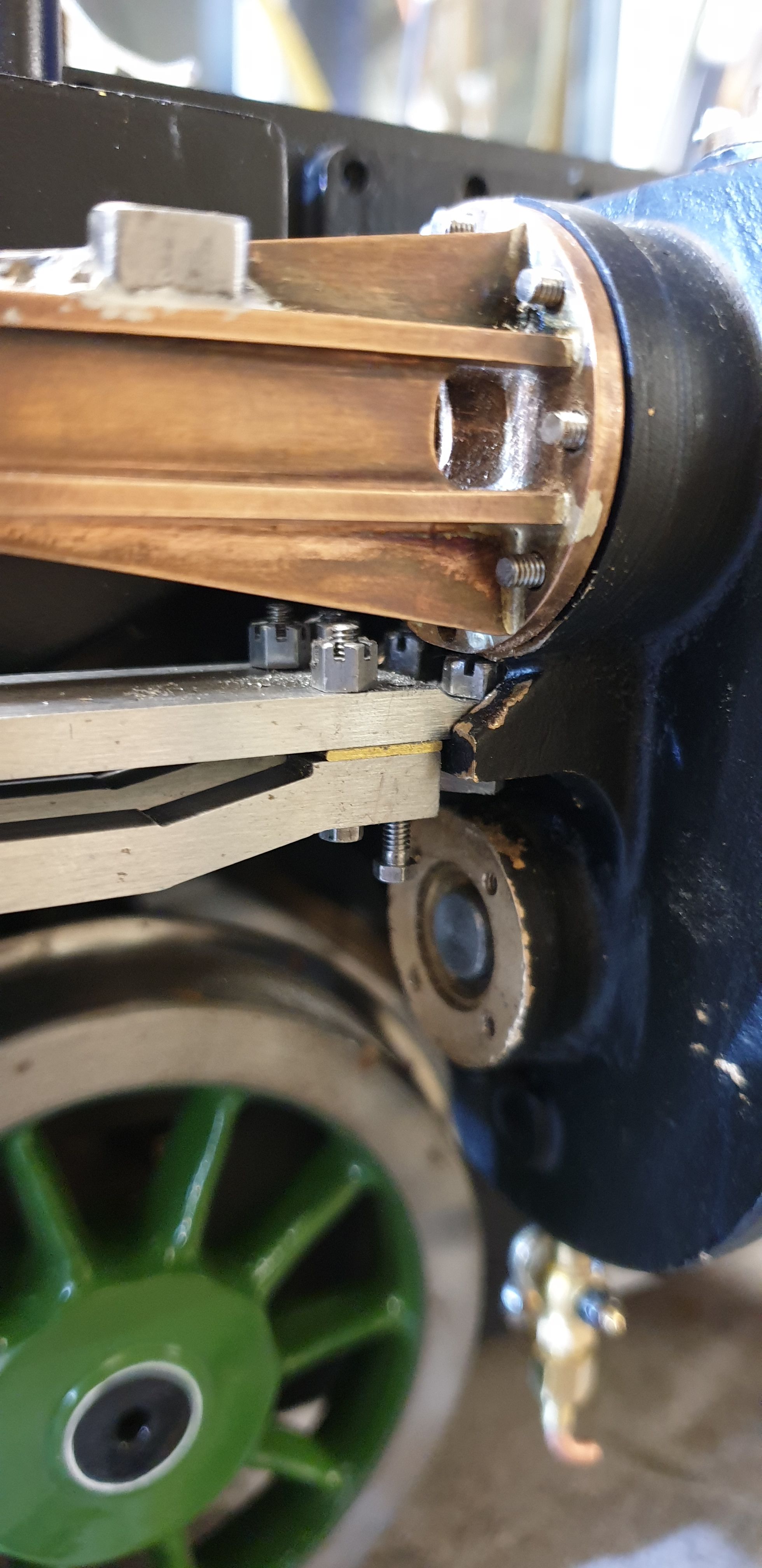
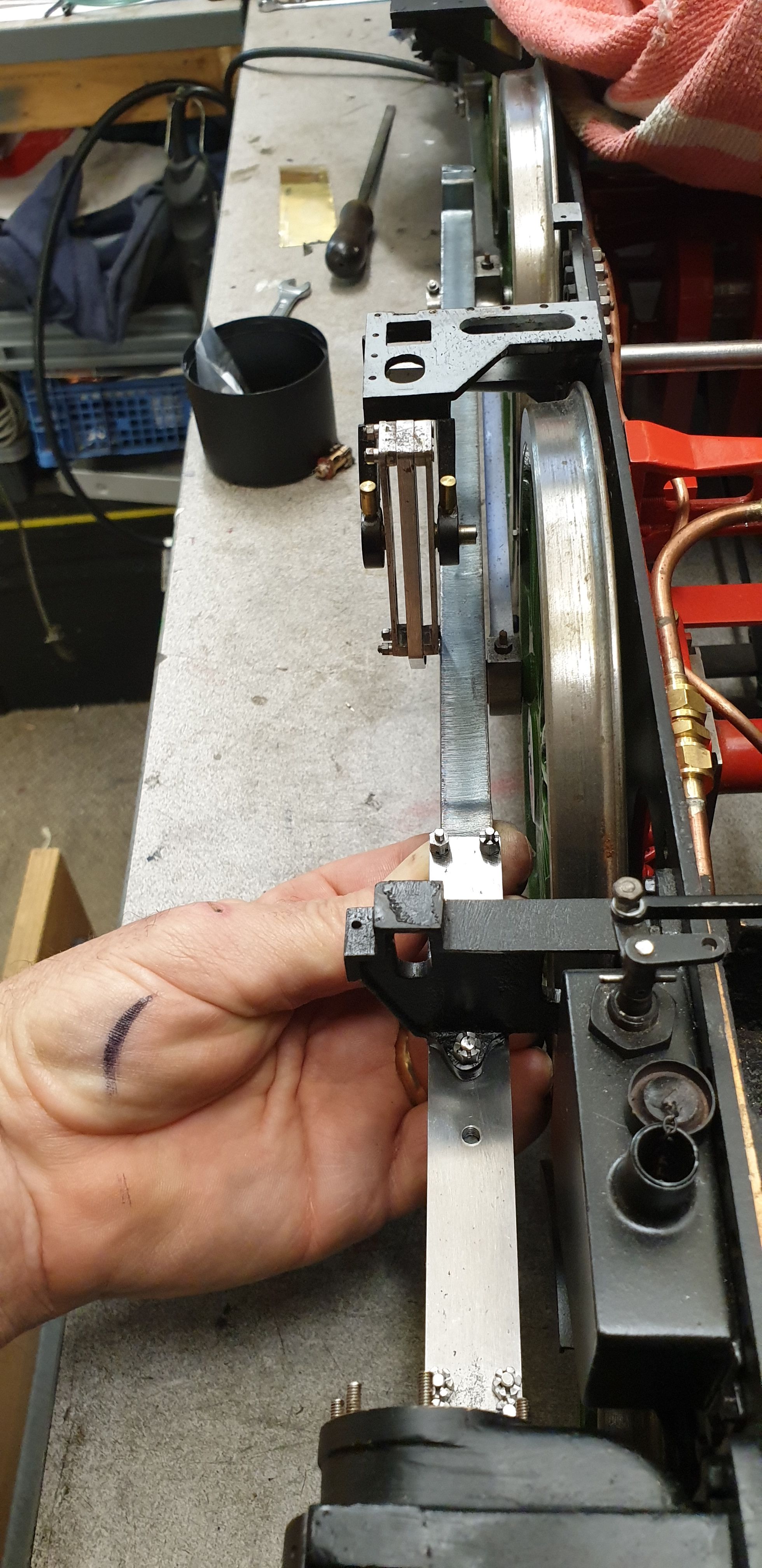
This picture shows the first attempt of fitting the slide bar, something that I had forgotten here even though I did make a note when making the bars themselves was that there would need to be a step on the top bar to be able to fit under the steam chest, well not the bar itself but the nuts that secure it down. You can see how close things are looking here and that the nut which will fit under the steam chest can't do so with the bar as it is. Me not remembering this meant that I had to remove the bars again and machine the step, I did both side2 L and R at the same time.
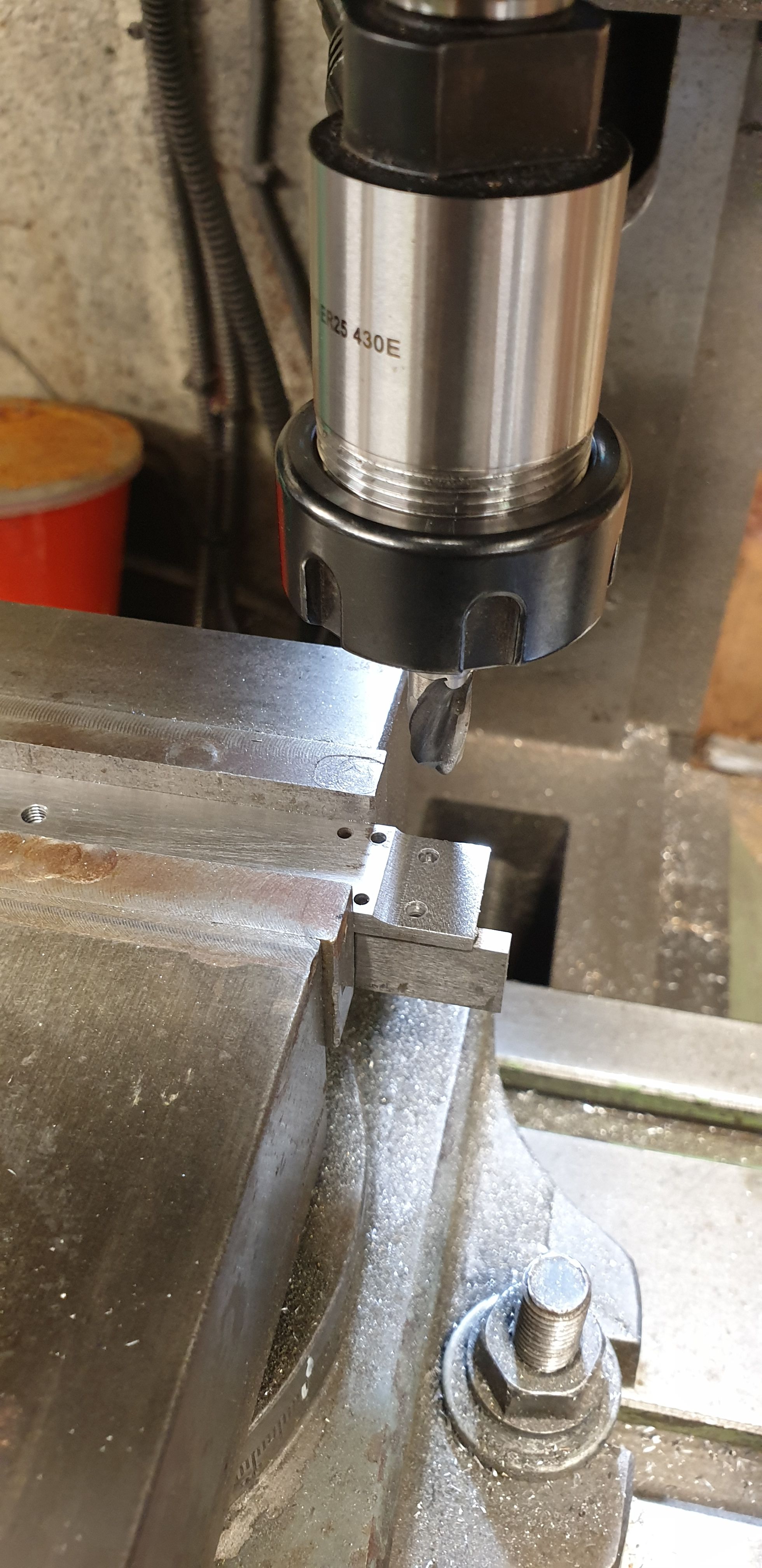
And so, back to the mill to remove some metal, I chose to use a ball nose cutter which a reasonably large radius, this was to give a little more clearance for the spanner to hold the nuts, this is something that later I was very glad I had done.
Another change in design, I believe that Don had stated to use 8BA bolts for the valve guide covers? I decided to use studs as on the prototype. However, the lowest stud wouldn't work or should I say it's hard enough to assemble these parts without a stud making life even more difficult. Therefore, I removed the offending stud and will use a bolt, I have put a temporary bolt in place to show what I am talking about. This bolt is more or less above the outside bolt hole.
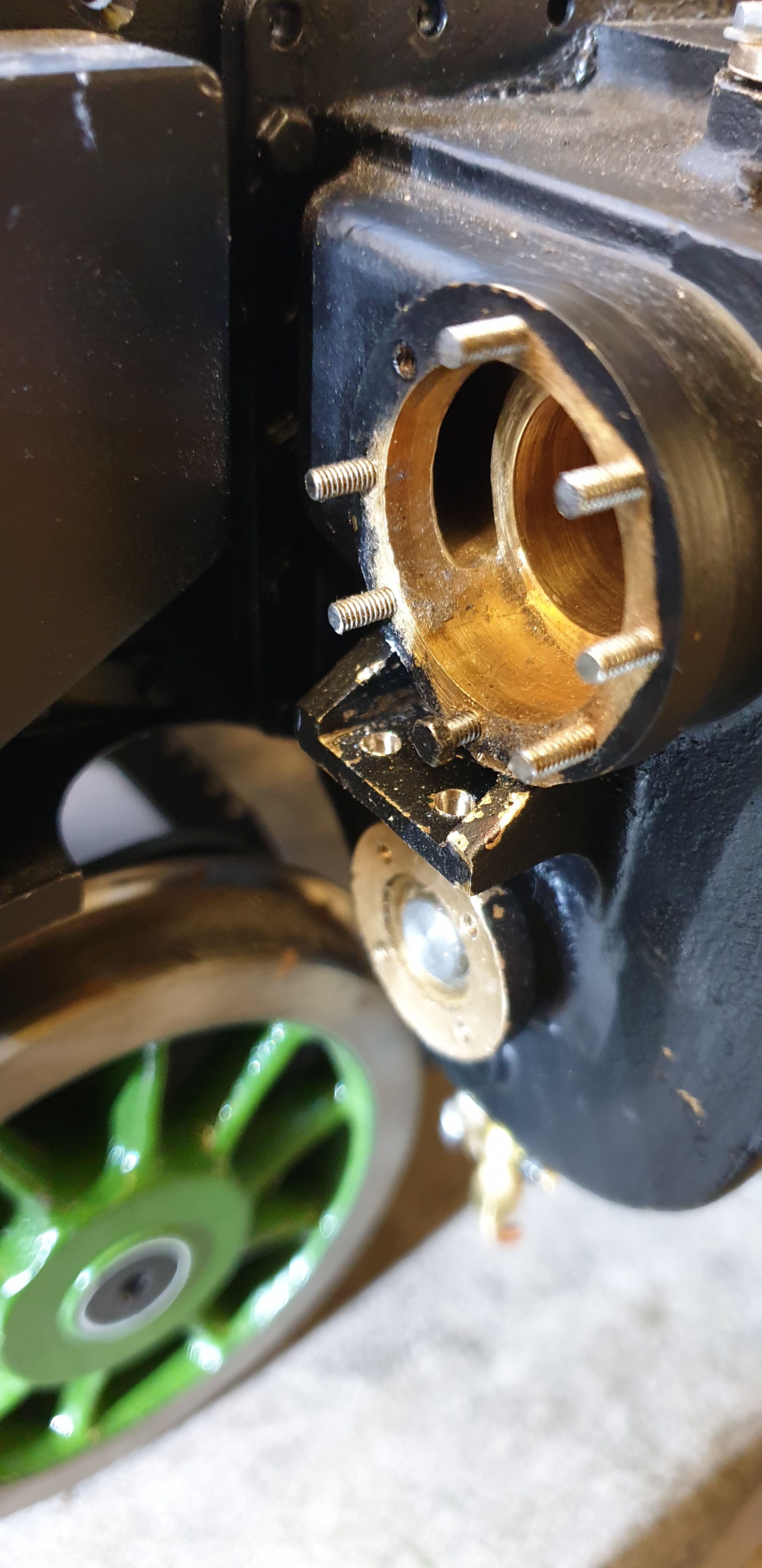
Here you can see how close these parts are and they can only be assembled in a particular order. Note that the leading bar bolt has been pulled down with the nut removed, like this the guide cover can be fitted, the 8BA bolt that replaces the stud can then be fitted to the bottom of the cover and lastly the leading bar bolt can be fitted... thank god these parts don't need to be touched often. Also to note is the nut that had to be shortened to get it to fit, it just fits. It's all pretty tight under there and if I had realised just how close before I may have machined the steam chest a little shorter to give more clearance. Anyway, it does all fit and it is fitted..:)
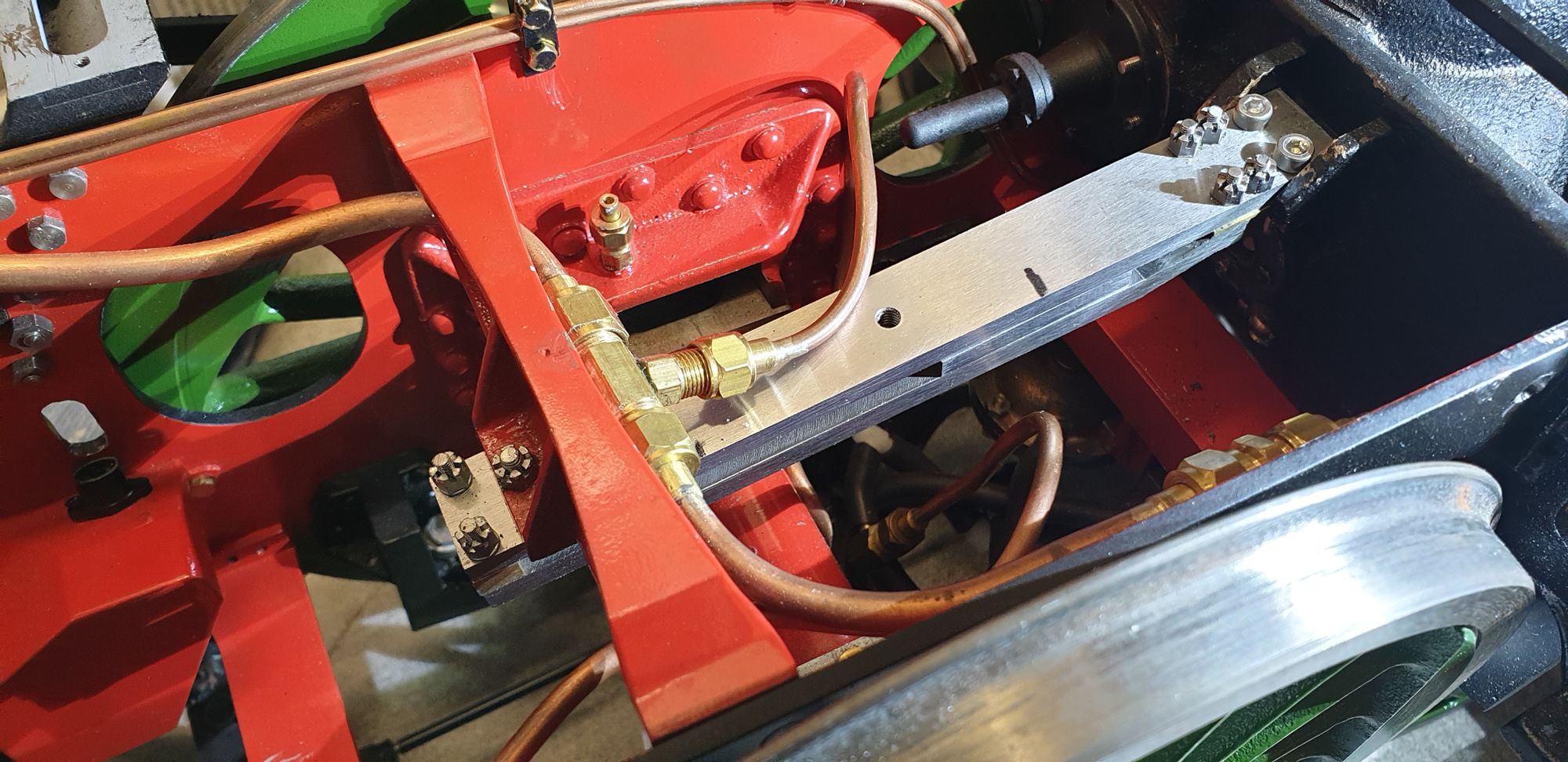
A rear quarter view of the R/H slide bar, note that the rear relief valve has also been fitted, I am using loctite suitable ( IIRC 567) for steam to seal these as I go, I'll also seal all of the pipework in the next few days before I forget. I have also touched in the paint were needed.
With the slide bar fitted I did a quick eyeball using the connecting rod blank to check on alignment, things are coming together and of course, the rod will be much narrower once machined to size.
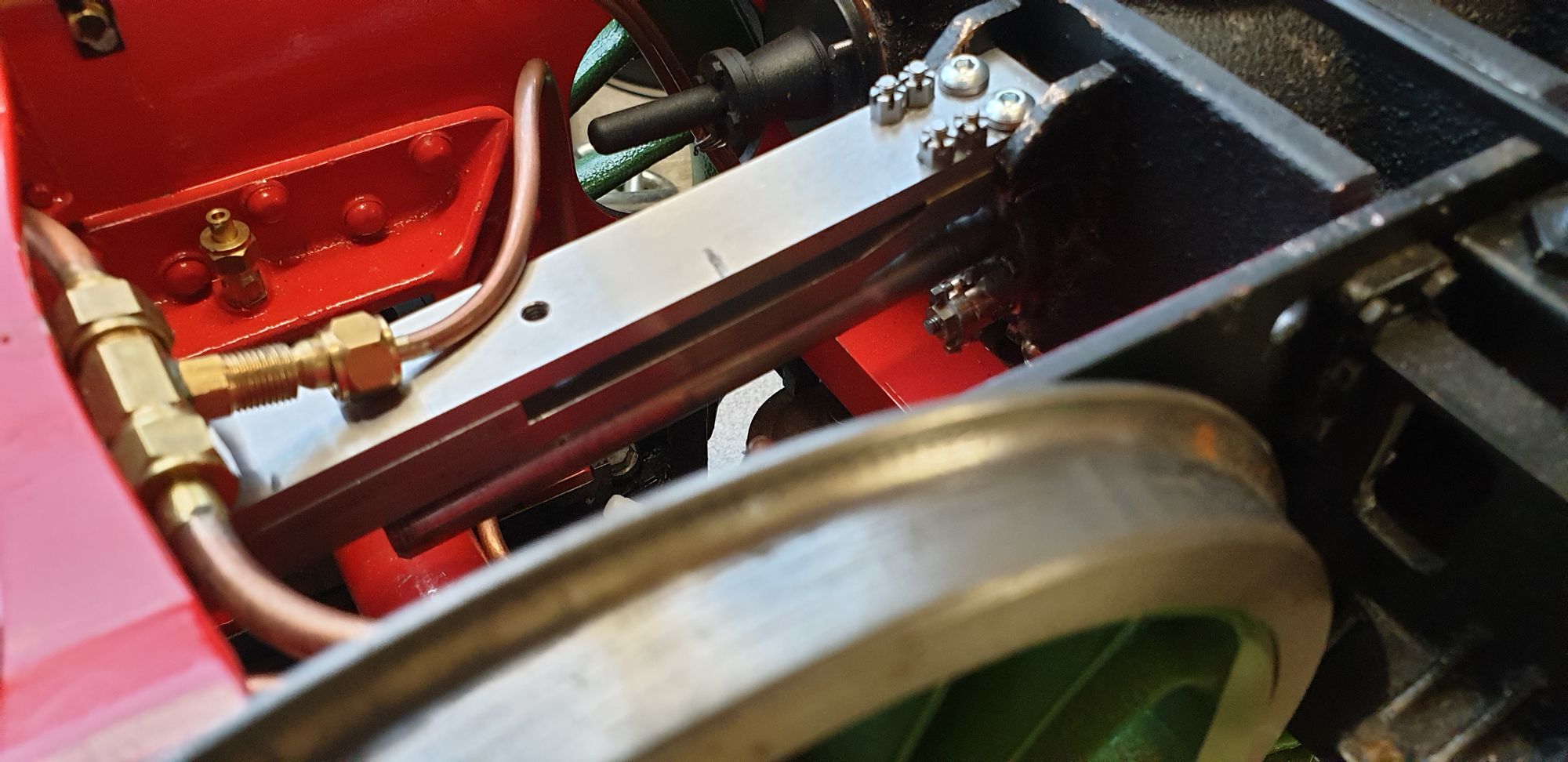
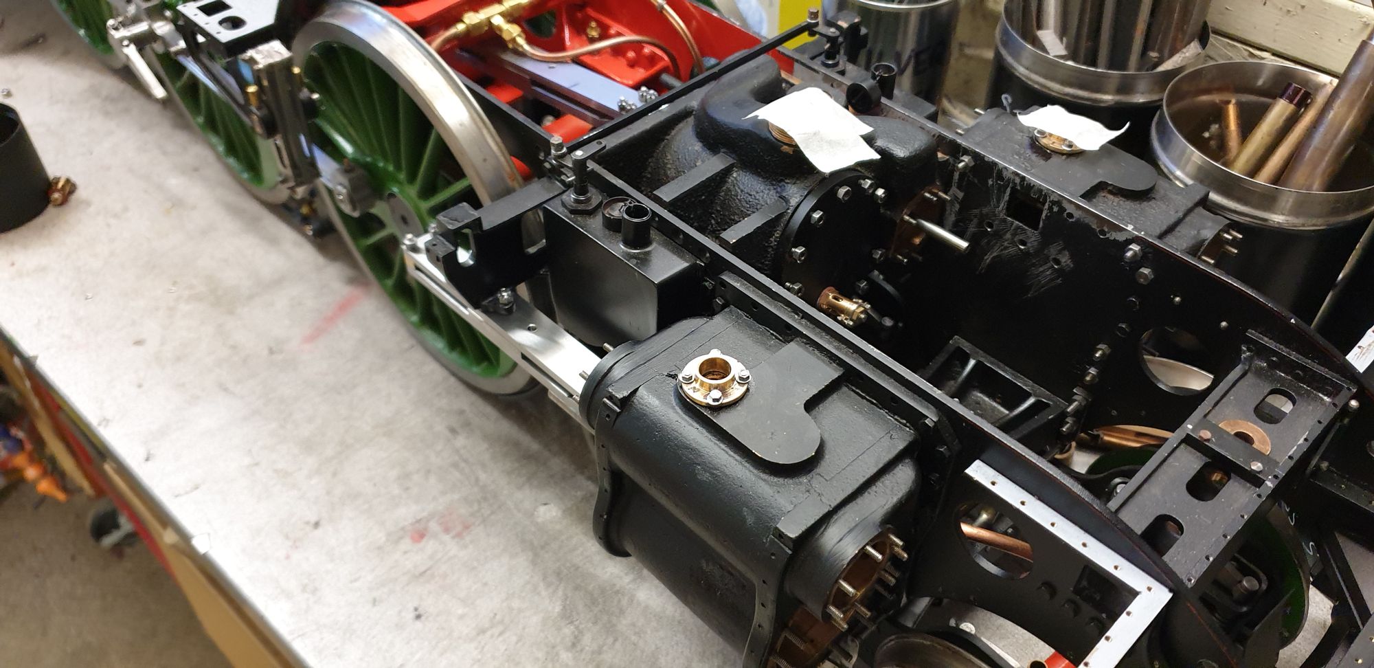
A view from above to show middle and R/H slide bars
And for the last picture for this entry a front quarter view...

Next, I'll fit the other side, seal the pipework and then either make the crossheads or machine the outside connecting rods. I suspect it will be the cross heads first to the 1934 pattern, if I get those done and make the bushes for the middle cylinder I'll be able to connect the middle piston and have a piston that moves when the chassis is pushed along....you know... playing at trains...:)