
Now this part is going to take some time and I guess there are a number of ways to do these either from solid or as parts. I'll be doing mine from solid except for the slipper which I want to have as a replaceable part, I will try to describe fully how I tackled these gems. I am using Don's drawing for critical dimensions as those are required to match the motion he drew but I will follow the prototype as she was for my chosen era. Thanks' to Eddie Gibbon's invaluable assistance, his research directed me to making the 1934 LNER crosshead pattern, I'll also follow this design for the drop link and oiling setup.
My approach when tackling something like these crosshead which is 'shall we say' a little out of the normal machining exercise, is to do all that I can first while still having large square flat faces, ie the blanks to work from. This means a lot of thought is given to the order of attack to such parts before actually cutting any metal, I don't always follow the plan, but so far the crossheads are being machined to a plan.
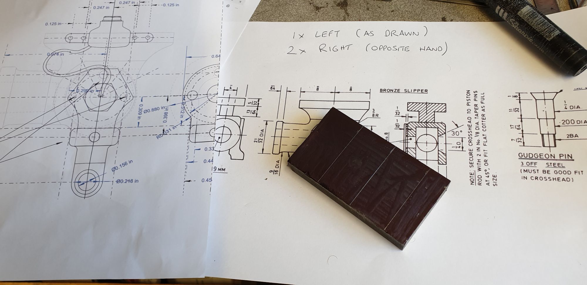
Don states to use Black steel, as it happens I had an offcut that was given to me which was big enough, well it would of been if I had remembered the extra material needed for the ridge . I'll explain shortly but to begin this entry here's a picture of Don's drawing and the piece of steel already marked out (wrongly). I cut to the lines and machined square. NB: the drawing partly seen to the left is Eddie's drawing which he kindly sent me of the works method for the gudgeon pin oiling reservoir etc.
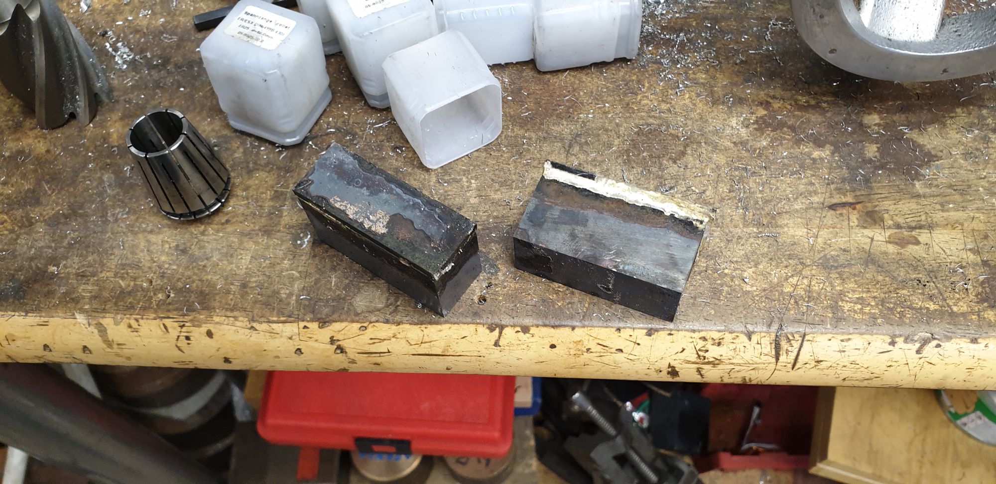
I then realised that I hadn't allowed for the planned ridge which would be my register for the slipper. Since the drop below which is part of the drop link support, was small and not a structural issue I silver soldered a length of steel to the bottom of each blank slightly thicker than required, IIRC the height allowing for the ridge worked out at 1.125"? This took a lot of heat but I succeeded it getting good penetration throughout the joint which was evident as I later machined the blanks down to their final size, which BTW took a fair bit of time.
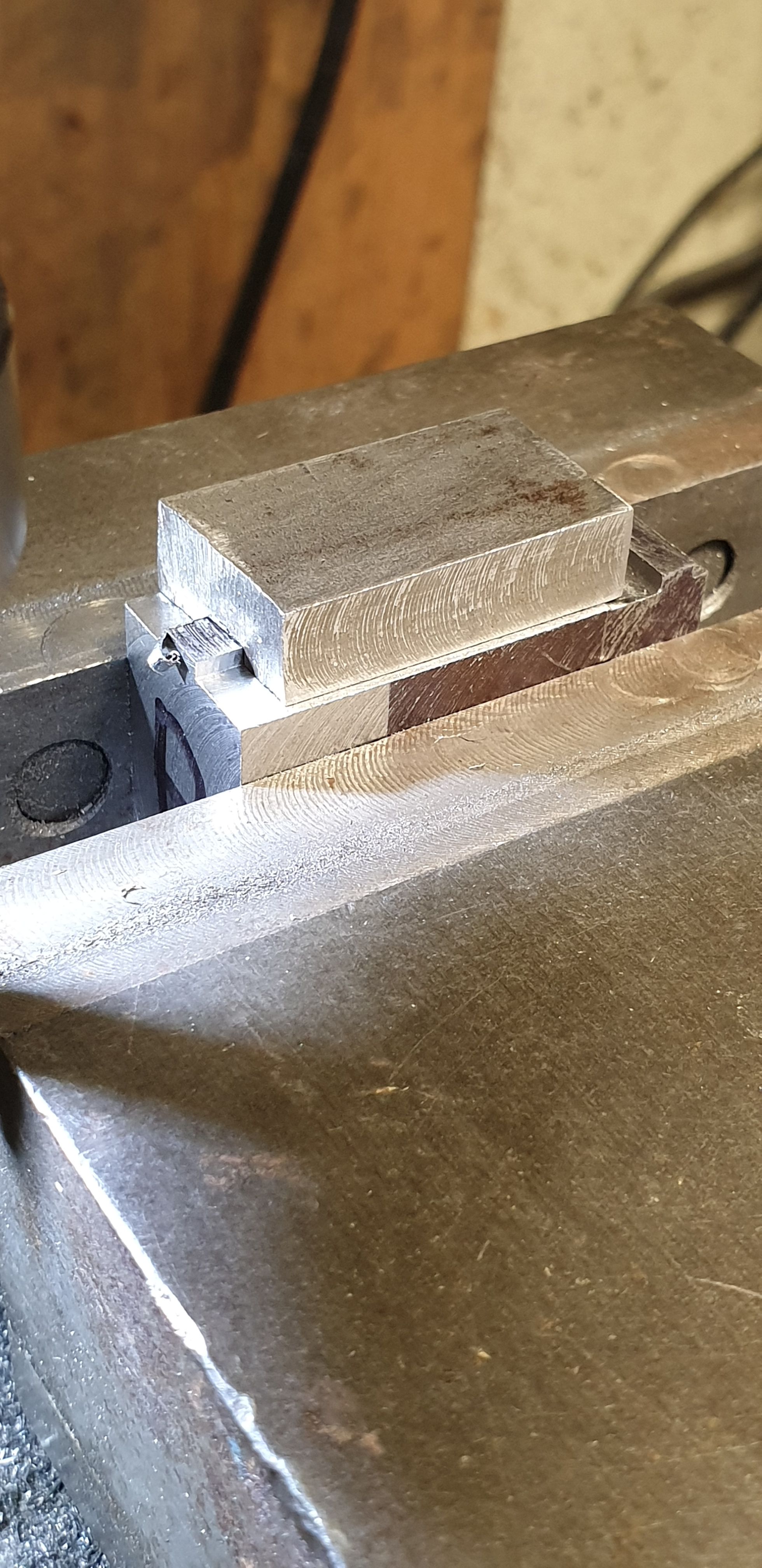
With the blanks to size, the height BTW I left a few thou oversize I then clocked each blank in the machine vice and machined across the width where the slipper would sit, this edge of the slot is 1.250" from the rear face. I chose to use a 5mm cutter and set the depth approx 70 thou, I'll explain why in the next picture.
With the slipper pad marked out I then machined away the top to give me a central ridge which is 1/6th high by 3/16 wide for the length of the slipper. I used a 8.5mm slot drill, this being large enough to easily remove metal but small enough so that I could cut the ridge side without cutting into the remaining part at the front. The reason for the metal left at the front is so that I have a large stable footprint for the blank to sit on squarely for machining during other setups. You'll probably note and I have done this many times before, I try to keep a good squared section for holding the part for future setups.
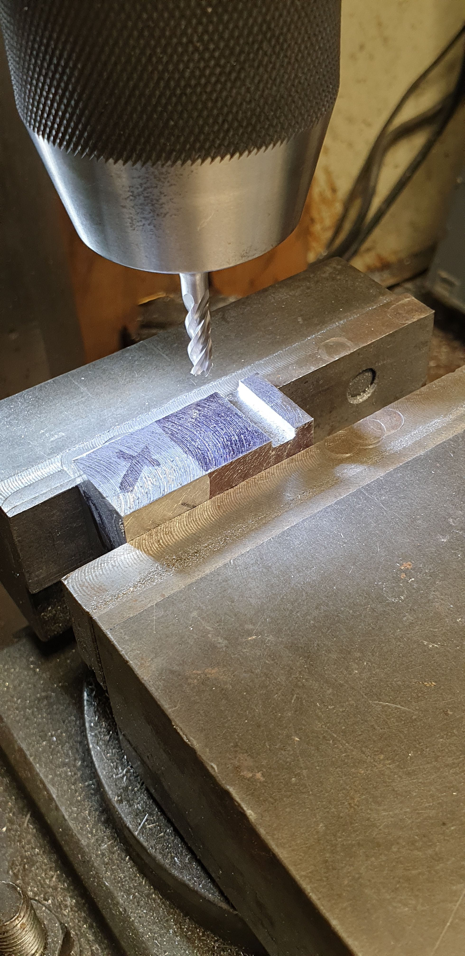
Before machining the ridge I cut a 3/16 slot into a piece of scrap steel and machined the top of the blank until the test piece required just a tap to be a snug fit. Once I had the DRO readings for the first the other two where machined in half the time.
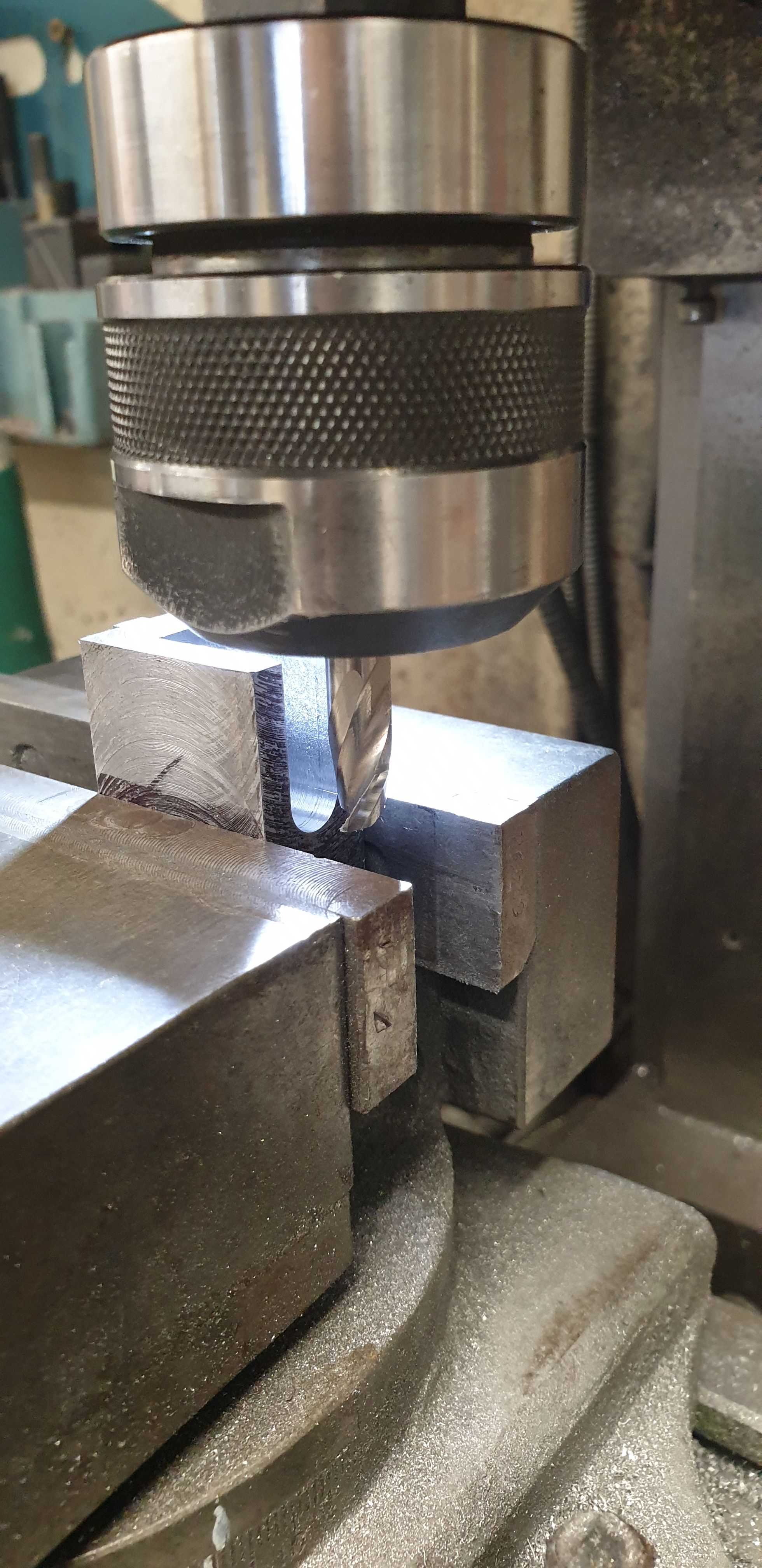
Next job to do was removing the insides of the crosshead, this was once again a long process but I got there in the end. After marking out the blanks and clocking in the vice I first cut the bottom face to the full depth of 0.765, I played safe and took it down a little more to 0.770 as I don't want any chance of the con rod touching. Much easier to machine the extra off now than try to remove it later once the crosshead is finished using a file. Length of the slot is 0.843 which I machined to drawing. I used a 8.5mm slot drill for this which is a few though undersize of the required 11/32 for which I did not have a suitable slot drill. The con rod little end is 5/16 wide so I think that the 8.5 mm slot should be wide enough still giving me over 0.25 mm clearance either side.
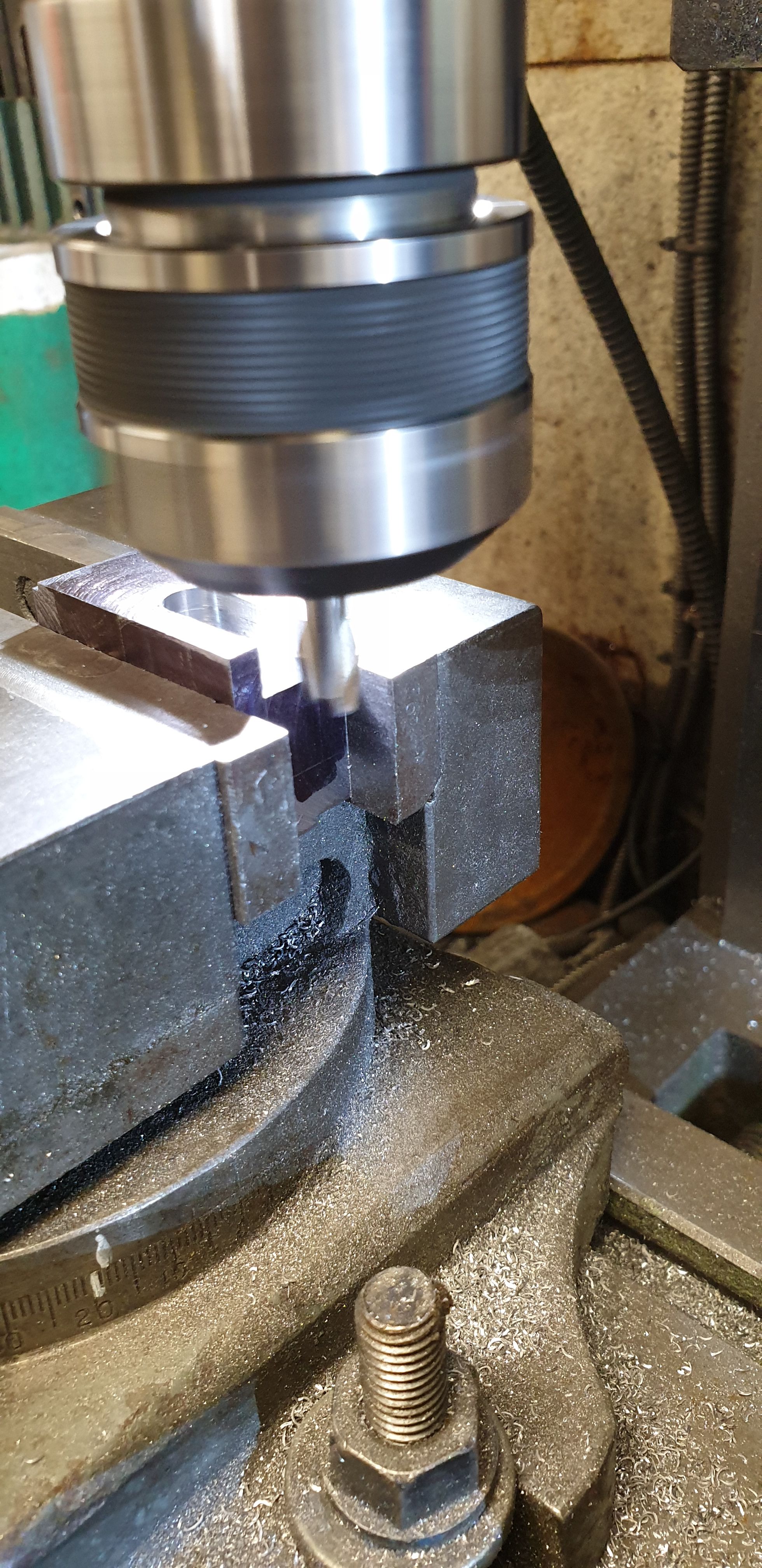
Once the slot had been cut from the bottom I then clocked the blank 90 degrees and flipped it around so that I could see what I was doing while machining from the back face. It was very reassuring to see that I had managed to get the centre correct as can be seen here after the first small pass with no step evident.
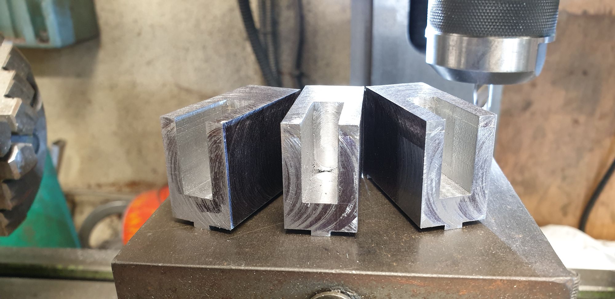
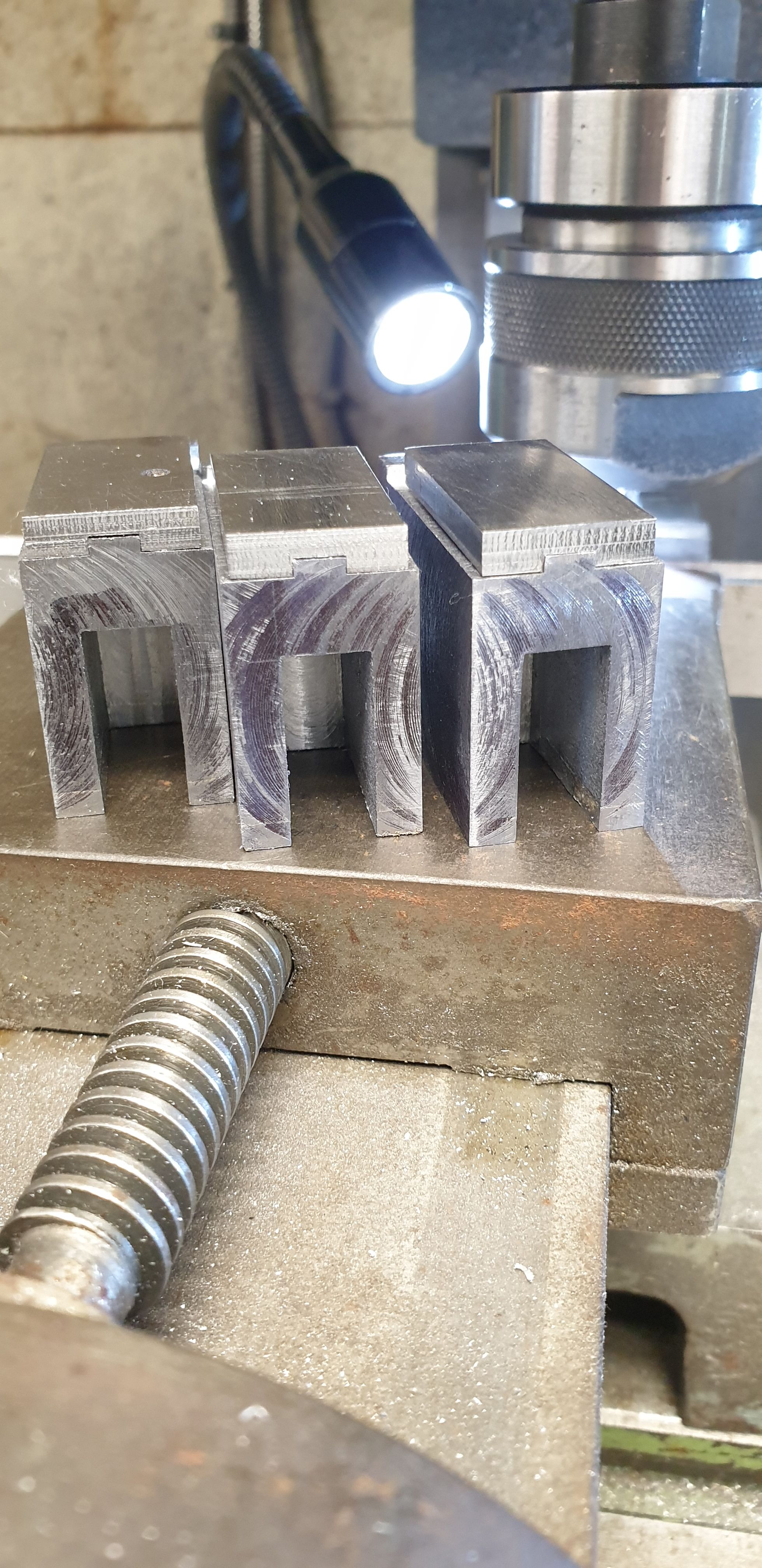
Here we have all three blanks with their slots completed, naturally there is a small amount of material left in the far corners but this is not relevant to the operation of the crosshead and clearance for the con rod and thus will be left alone. Another reassuring thing to note here is that I clearly managed to get full penetration for the silver solder joint between the two parts of each blank. The small gold line seen near the top is the silver solder joint. As mentioned earlier there was a lot of heat used here, in fact the workshop was full of smoke, looked like it was burning from the outside.

Last job done for this update was to make a start on finishing the slippers, lots more work to do here but you can see that i have now machined the slots for the slipper to loate centrally onto the crosshead.
In the next update I will continue with the slippers and also make a start on shaping the blanks.