
Continuing on with the crossheads and we have 11 pictures for this entry, I have tried to do the talking with pictures in an attempt to give a clear indication of how I am tackling the various machining processes and in which order. Oh, and yes there are some machine marks on the vice, some are mine, others from the previous owner, it's an old vice... at times I just get too close...:)
First, I'll continue with the slippers and how they will be lubricated with oilways machined into their surfaces. Before doing that I needed to form a reservoir in the middle of the top face and also drill 4 small holes to allow oil to seep through to the two lower slide bars. the reservoir was formed using a ballnose cutter.
With the holes drilled from the top I then turned over each slipper and using a small ballnose machined 4 short scallops for oil to spread over the two lower slide bars forming a film between them and the slipper.
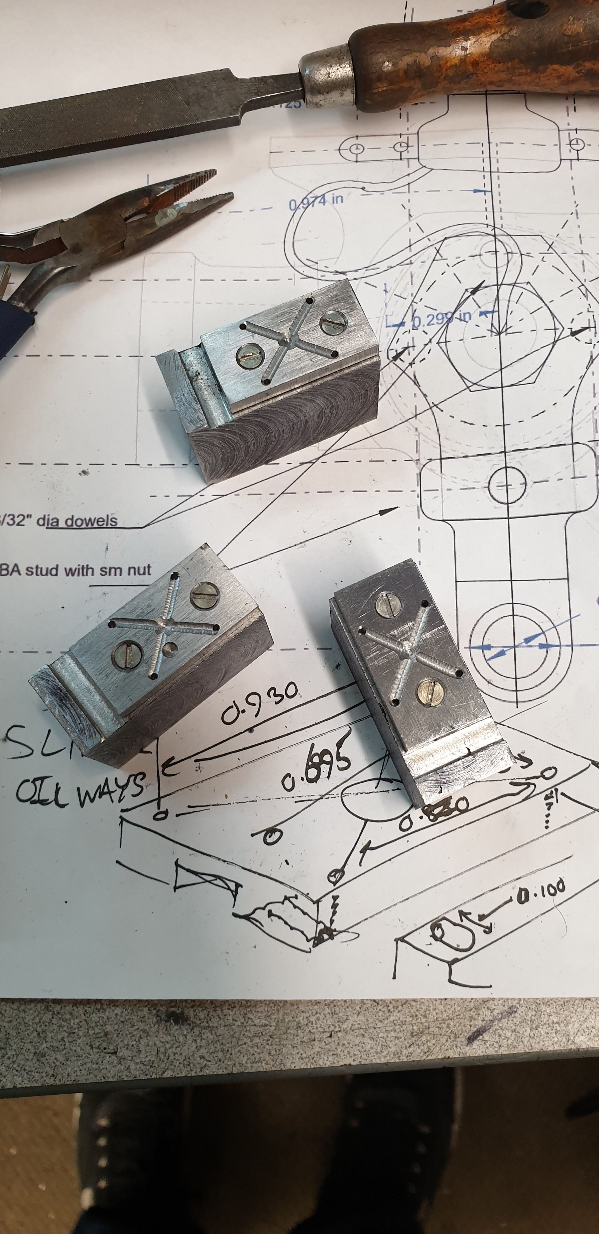
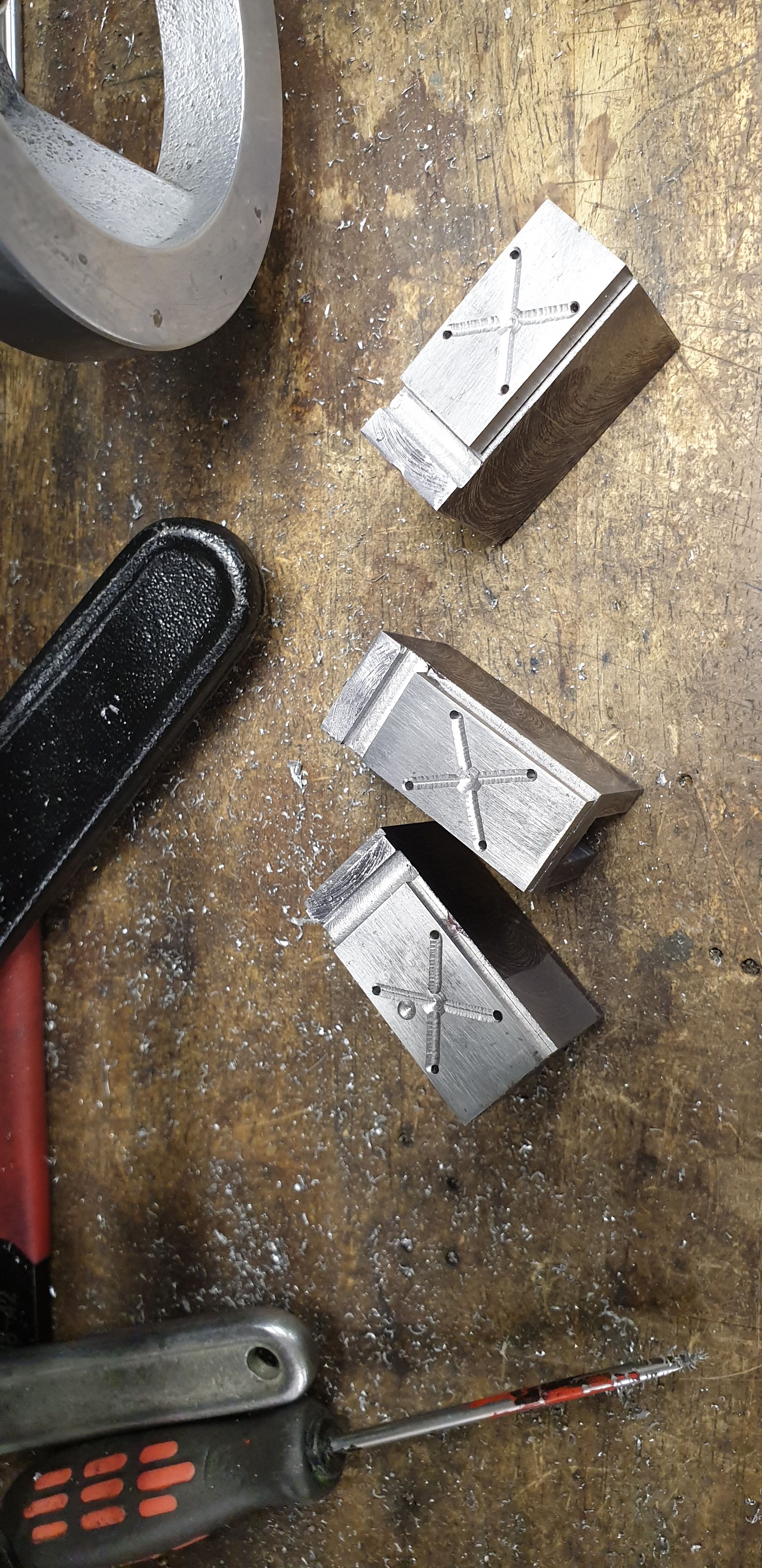
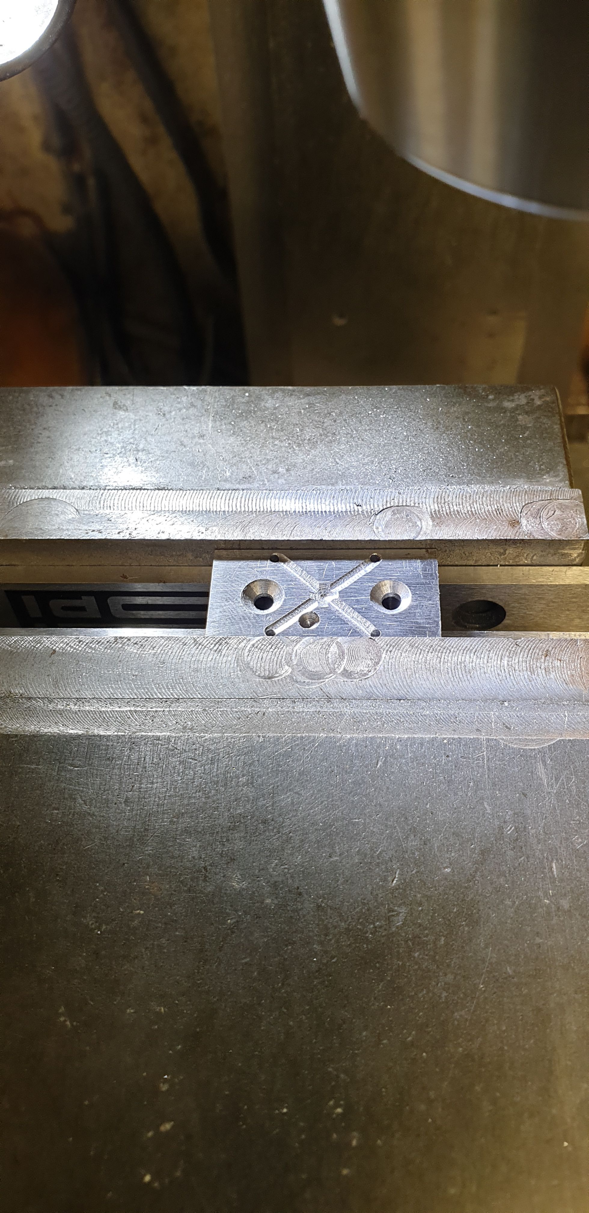
The slippers were then turned over again, this time to machine more scallops, this time in a cross pattern between the oil holes and through the reservoir. The picture shows all three done so far.
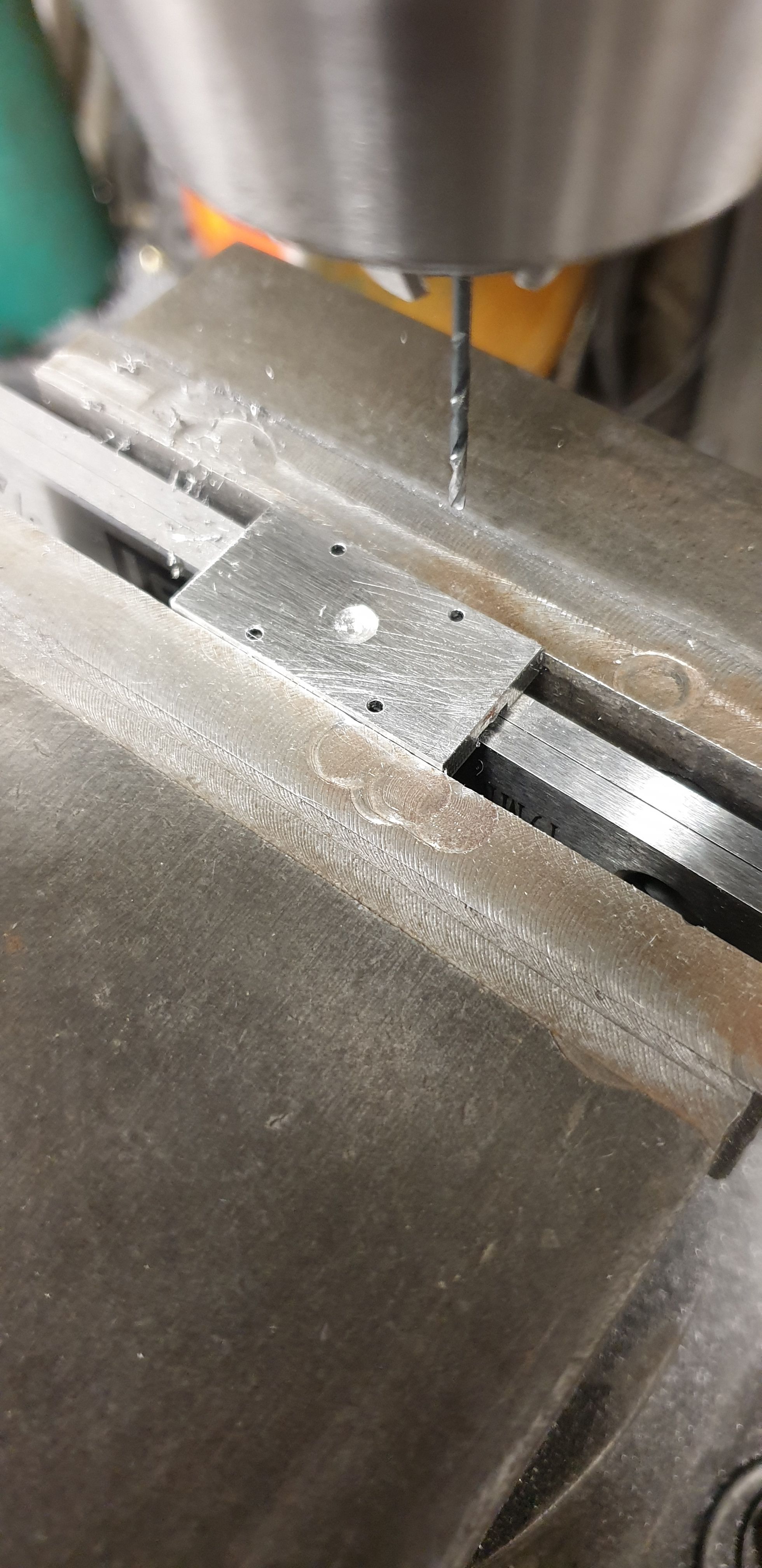
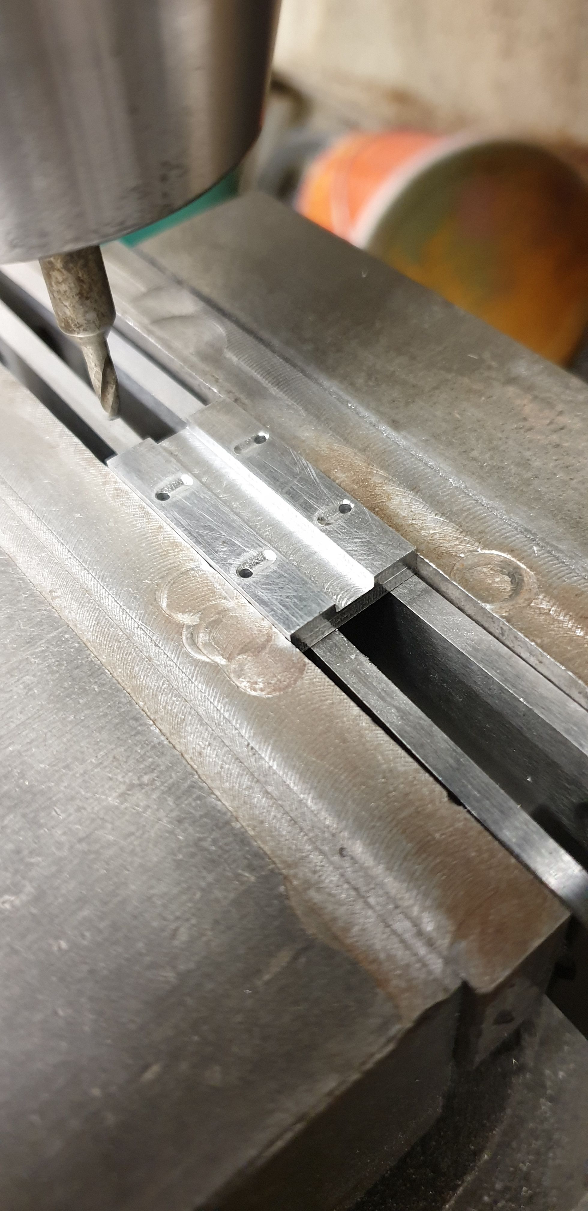
It was then time to temporarily fix the slippers to the crosshead body, I have chosen to use 6BA CSK stainless screws for this job. I have made the slippers separate as a serviceable item but hopefully these should last many years with the oiling keeping a film of oil between the three gauge plate surfaces. Here we see one of the slippers being drilled and csk after first plotting the hole positions. Note the extra dimple, no it's not something clever, it was a silly thing that I did some time ago when drilling a hole into something and not realising that one of the slippers had been left on the bench and somehow found its way underneath... oh well, count it as an extra oil reservoir...:)
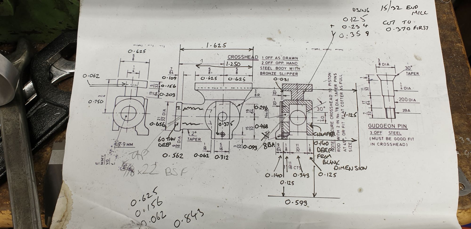
With the slipper positions sorted it was now time to drill the various holes in the crosshead body. Before showing you that, this is the state of my printed off drawing after working out how and in what order i was going to machine these parts. It's getting a little messy, you should see the slipper notes...:)
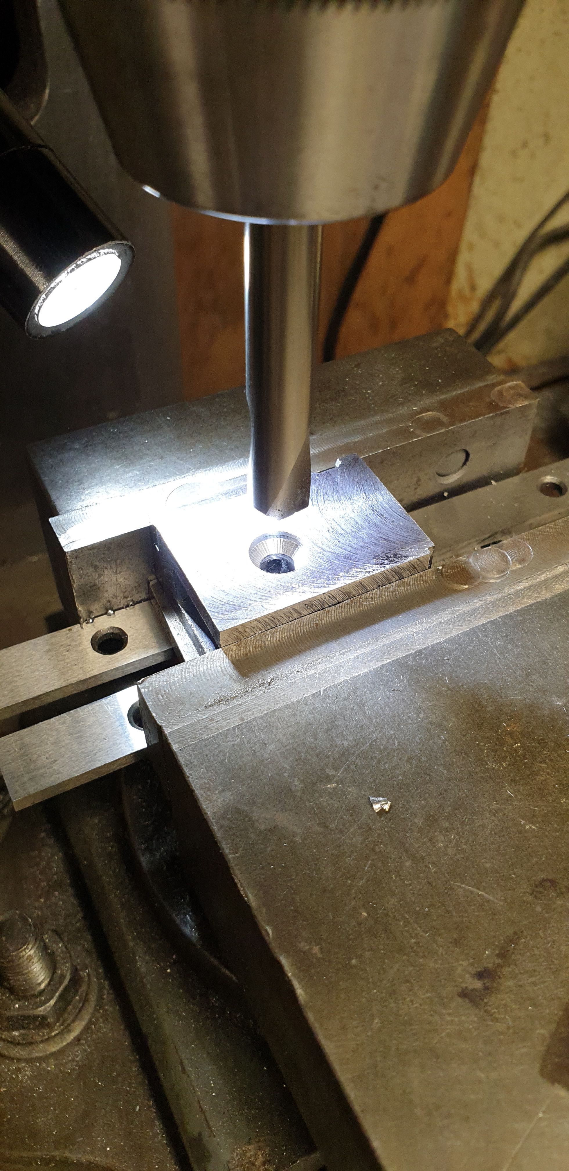
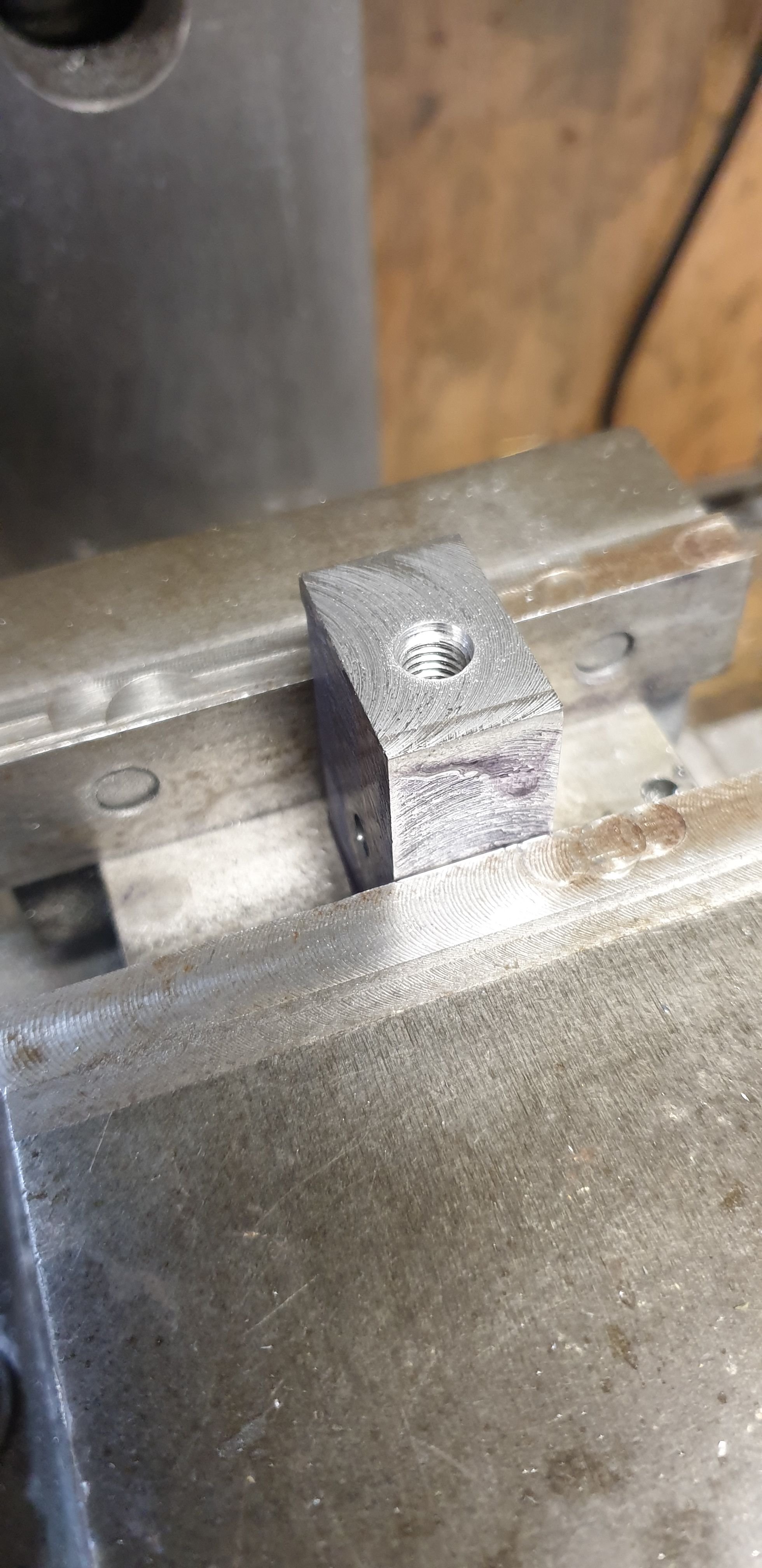
Ok, so the first job was to drill the cross hole for the gudgeon pin. I should point out here that the reason I fitted the slippers first was that the critical dimension here is the 0.750 down from the top of the slipper to the gudgeon pin, The same dimension is ,of course, needed for the piston rod bore and with the machine vice clocked where it is, I can do the bore later after doing the two sides of the gudgeon pin first without moving the 'Y' axis which was zeroed at this setting. You can just see the lower hole below the gudgeon pin hole, this is for the drop arm although there will be others added as I will follow full size for my chosen era rather than as drawn by Don which shows the 1948 pattern and for this the drop arm was welded in place.
I have tapped this hole 8BA rather than Don's 7BA, for lining up the drop arm and the locating plate that sits behind which has another 8BA stud and two dowels. For these details I'll be following Eddie's excellent 1934 drawing.
With the outside holes drilled I then turned over the crosshead, replotted the gudgeon pin hole and opened it up to 1/4", finishing with a CSK drill to give me the 30 degree chamfer for the pin to sit in. Don's drawing shows the chamfer going all the way to the end of the hole, I have stopped it short a little to ensure that I have a good fit with the 1/4" rather than as drawn which shows no 14" section, that seems a little dicey to me if the CSK went to deep opening up that 1/4" hole. Hope that makes sense? The CSK has cut into the side a little as this face still needs machining to size.
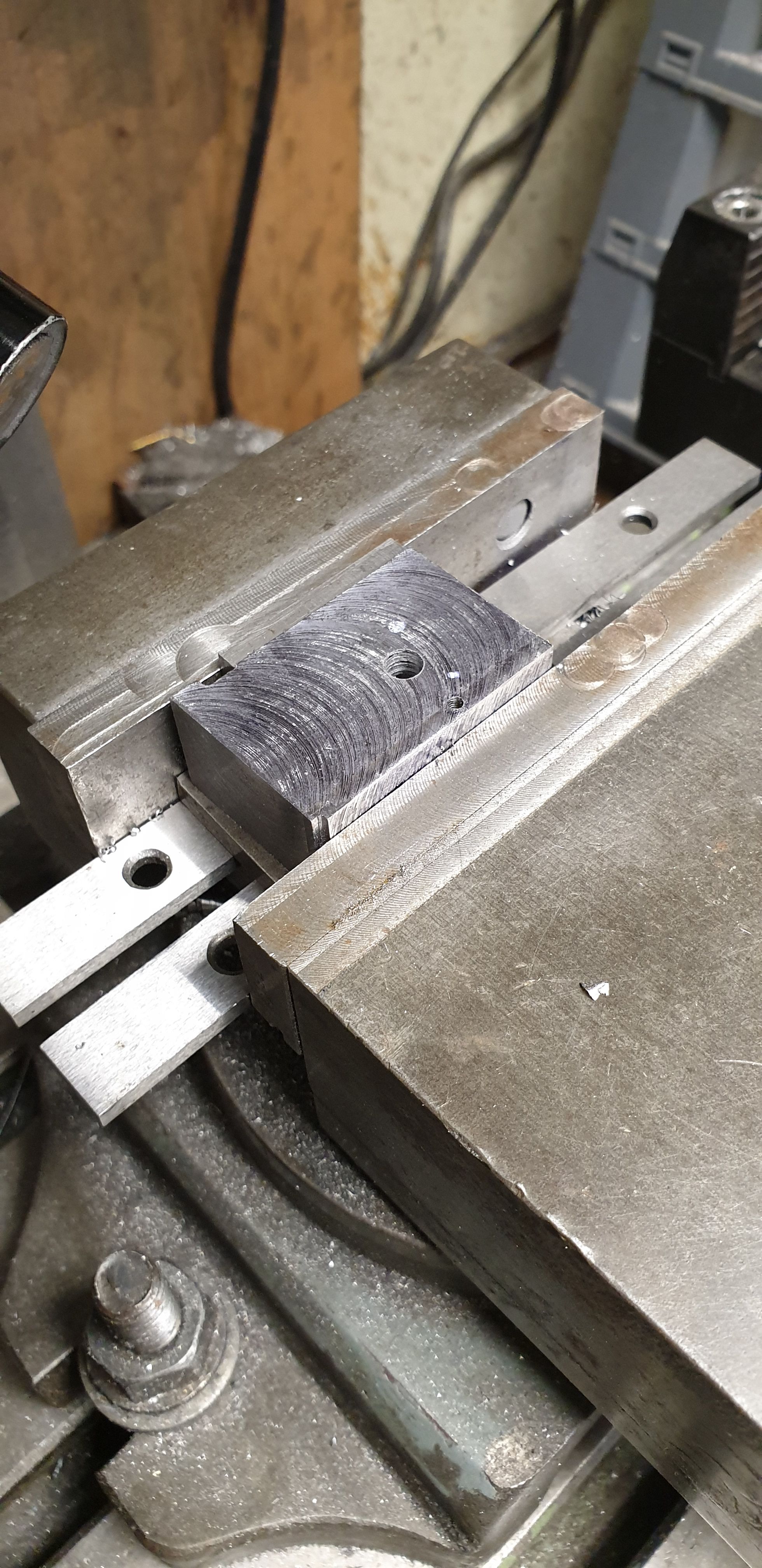
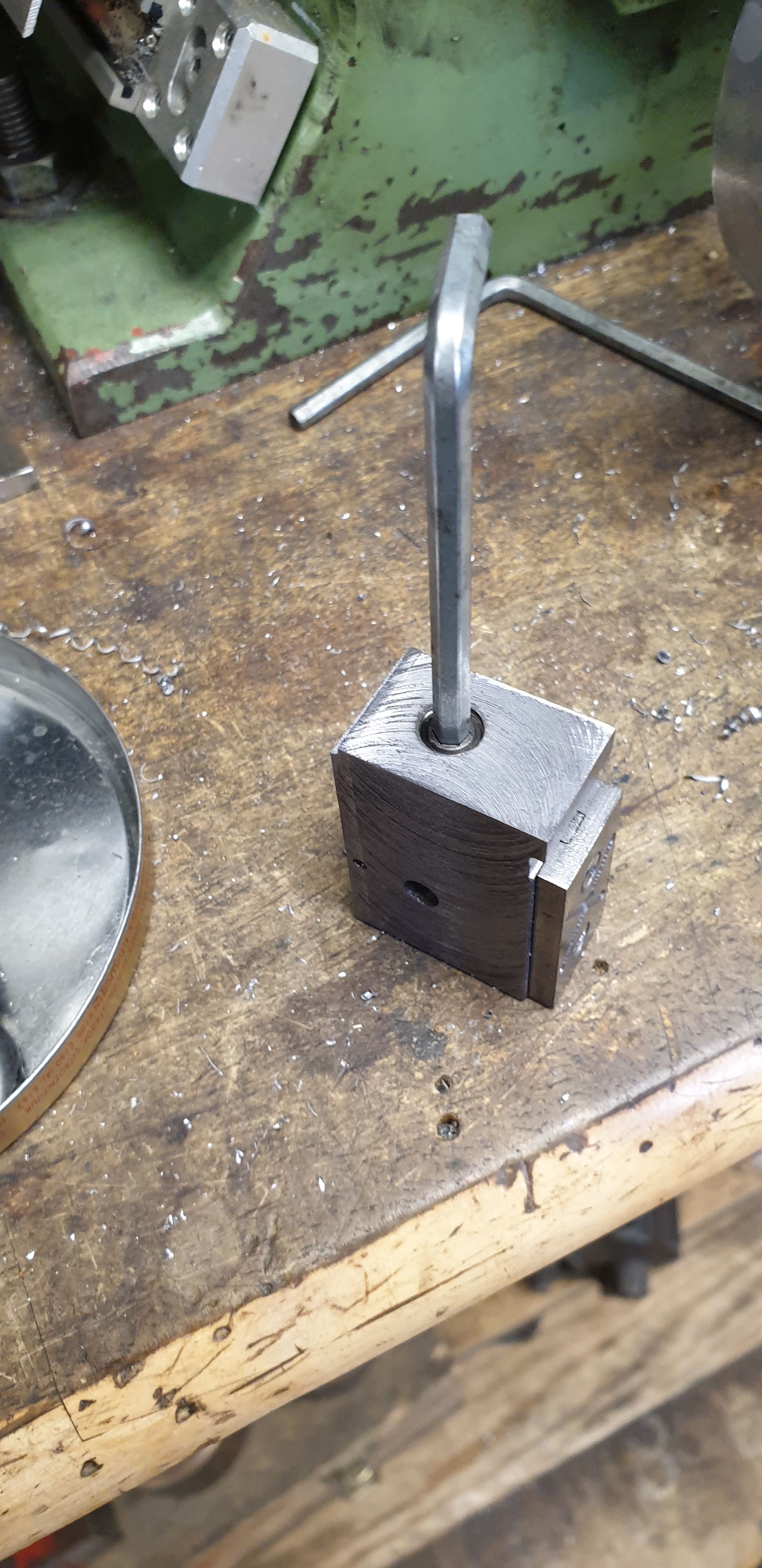
With all 3 crossheads to this stage I then concentrated on the piston bore hole and for this I have again changed from the drawing. After talking to fellow engineers I have decided to thread the bore and rod to make life a little easier for setting up the piston position. For this I am using a 5/16 x 22 BSF tap and die as it suits my 5/16 piston rods. The changes are not stopping there though, after another chat, this time with Reg Rossiter who came up with what i think is a great idea and that's to use a 5/16 grub screw to not only set the rod position if removed but also to tighten against, this and the tapered pin should ensure no movement in this important assembly. The grub screw will be screwed in from the rear, easy enough to do with the con rod dropped although once set in it's correct position is unlikely to need removing. The picture shows that the hole has been drilled/tapped and also had a short depth plain 5/16 machined with a suitable cutter, I chose to machine this to 0.060. This is for two reasons, one so that the thread on the rod is not seen once assembled and two, to enable me to clock the crosshead in the 4 jaw later.
The final job here was to check that the grub screw was easily threaded in from both ends with no stiff spots.
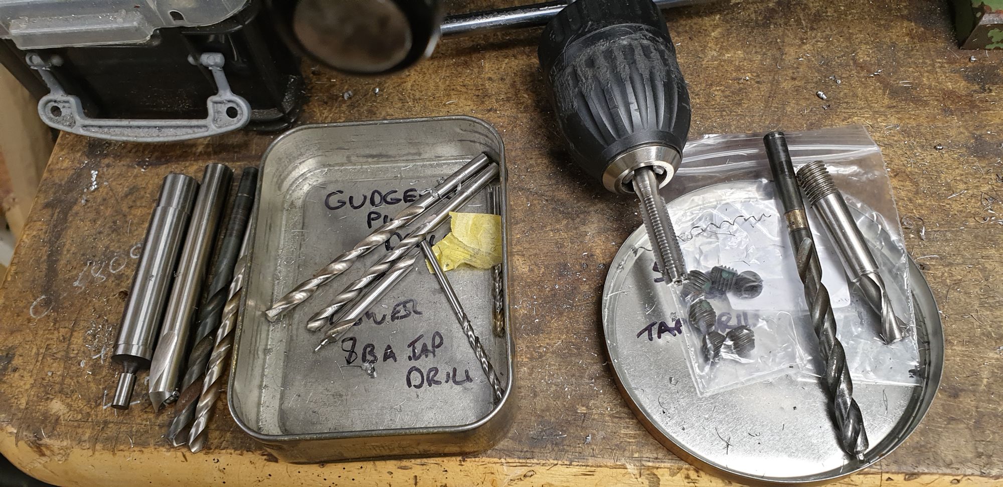
Last picture is just to show how I sorted out everything required before cutting starting this stage. All holes were carefully step drilled except for the 1.8 mm tapping hole for the 8BA. I kept everything seprate as some of the drills are close in size and the last thing that I wanted or needed was a mistake here. Left hand side is for the rear of the gudgeon pin, middle in the tin is for the front of the gudgeon pin leaving the right for the piston rod bore.
The next entry will cover the 'T' section for the slipper support, the sides machined to size and hopefully, the first turning operations in the 4 jaw.