

Before starting I need to add something that I forgot to state and that's that, the crossheads are handed and this was taken into consideration when drilling the holes which are different either side. The left hand crosshead has it's nut (naturally) on the outside (left handed) and the middle and right hand cylinders have theirs on the right. The middle cylinder doesn't have the drop arm mount which makes life a little easier for that particular crosshead.
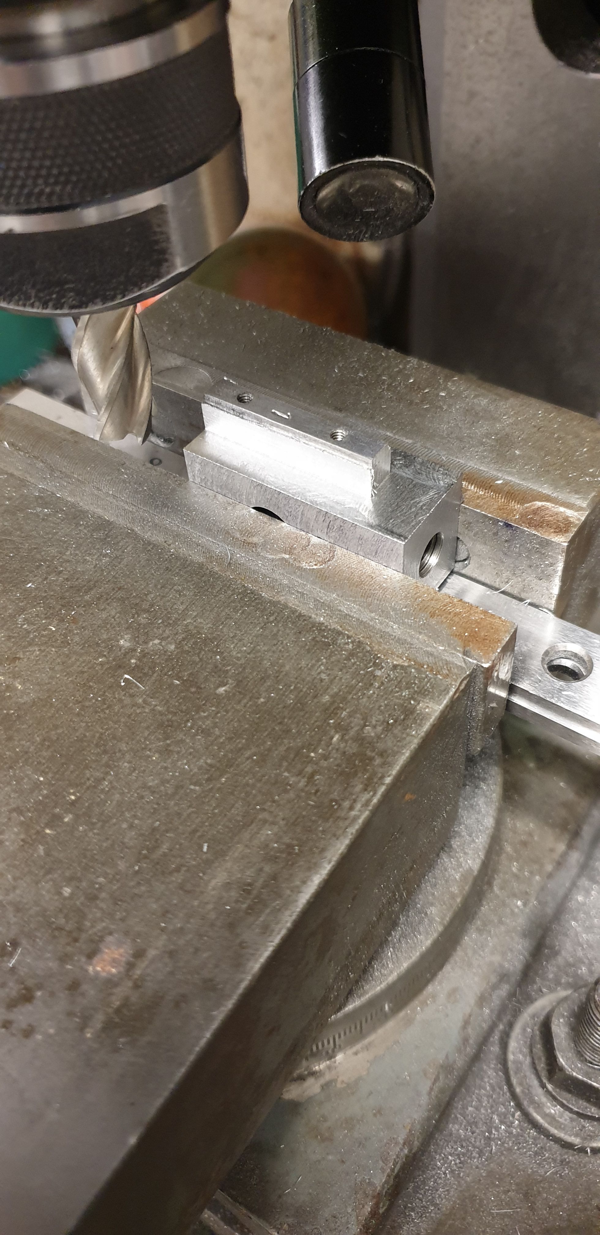
The next job was to mill the top face to create the pedestal which the slipper sits on. The width is 1/4" and the overall length is 1.250", height is 0.203. As before the part was zeroed on the 'Y' axis which was then set for machining the top and side faces.
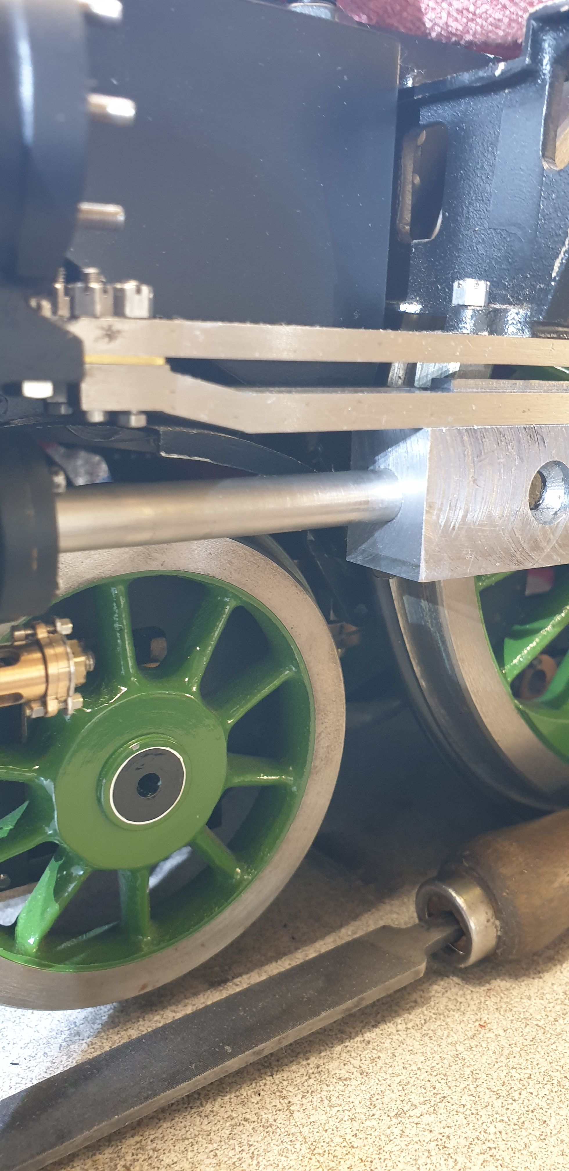
Reaching this stage I able to check for the first time that all was going to plan with the slide bars and piston rod relationship. I 'checked to fit' each crosshead as it was machined to see how things were looking, I was pleasantly pleased with the results. I'll show just two of the fits, I did take a photo of the other side but I think you'll see from just two, all 3 fit nicely. Here's the left hand side...
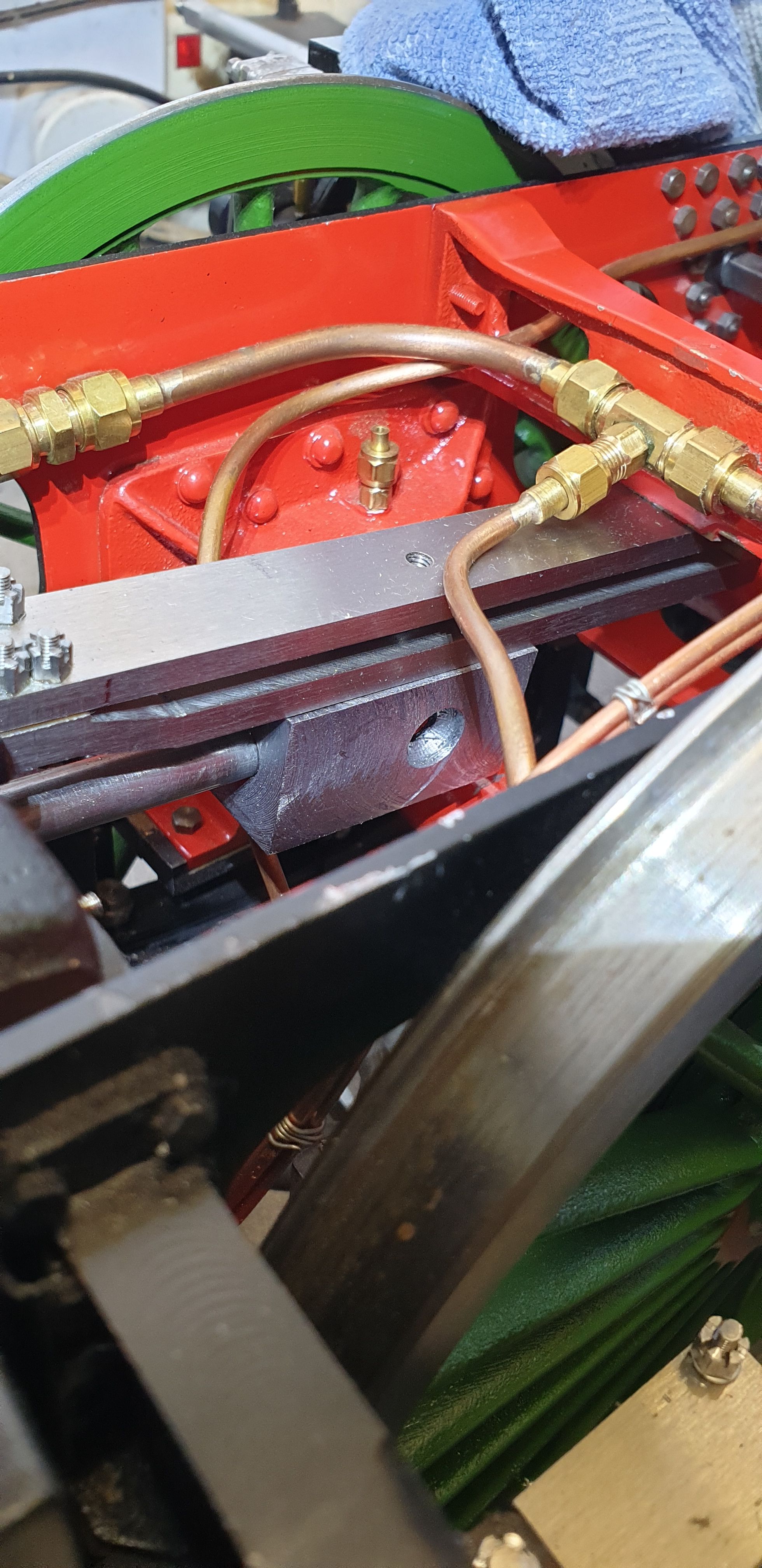
And the middle cylinder...
With 'Y' still zeroed I then machined down the side faces to their final dimension of 0.592. For this job I upended each crosshead, set it on parallels giving me just enough clearance for the cutter. At first I calculated my DRO measurements for a 16 mm cutter but on the first past could clearly see that the tip had lost too much of it's tip and was cutting shallow by a couple of thou. I then tried the 5/8 cutter which had cut the main horns and found this to be fine, I therefore recalculated to allow for the smaller dia cutter. For those who like figures, this meant a change on 'Y' from 0.612 to 0.6094. This picture shows the first side machined, another thing to point out is now that the side has been machined to size the CSK step which I mentioned in the last entry has now disappeared.
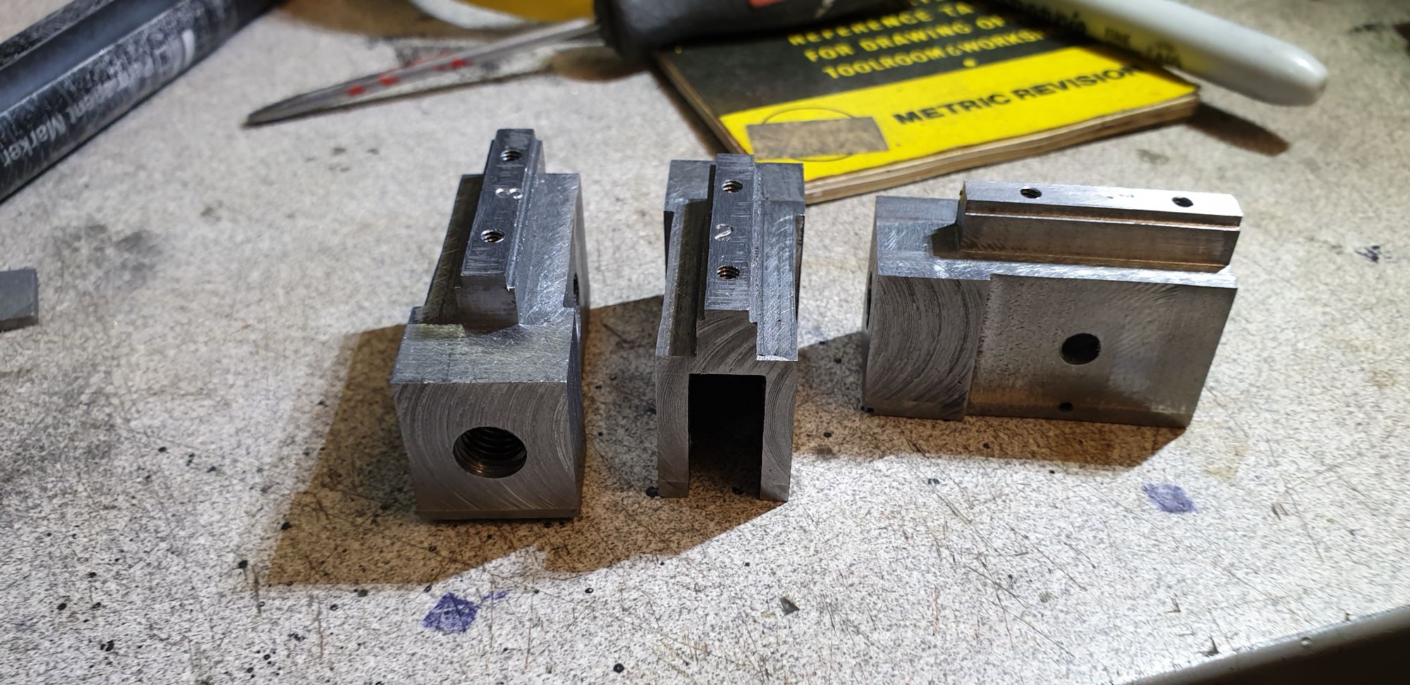
Here we have all 3 crossheads at the same stage, I have placed them at different angles to show the overall shape. this is the last picture where the parts still have 6 flat faces, things will begin to take shape from this point onwards.
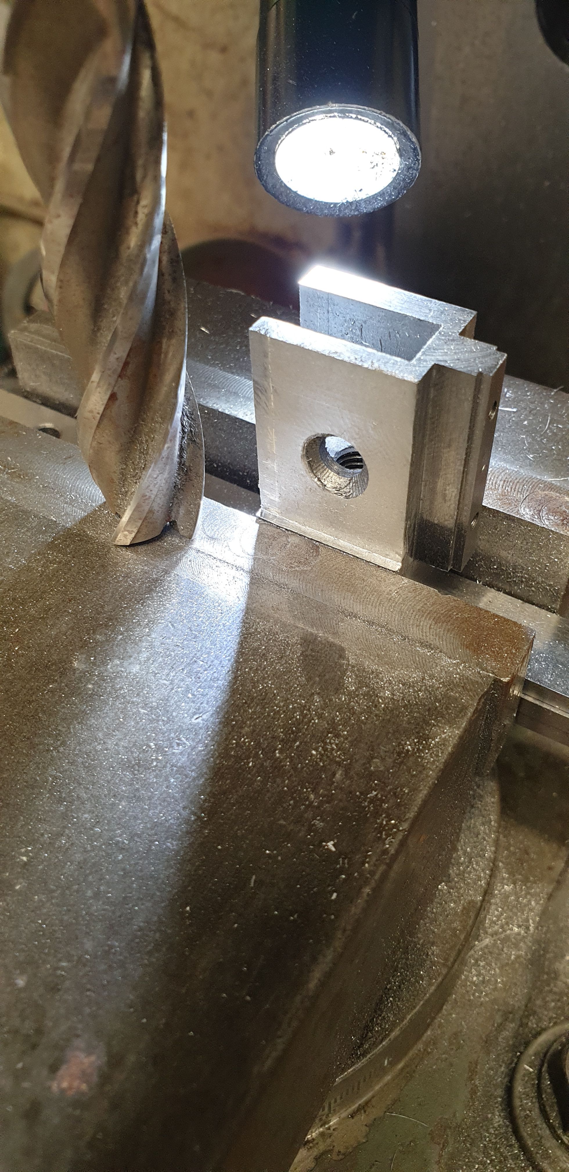
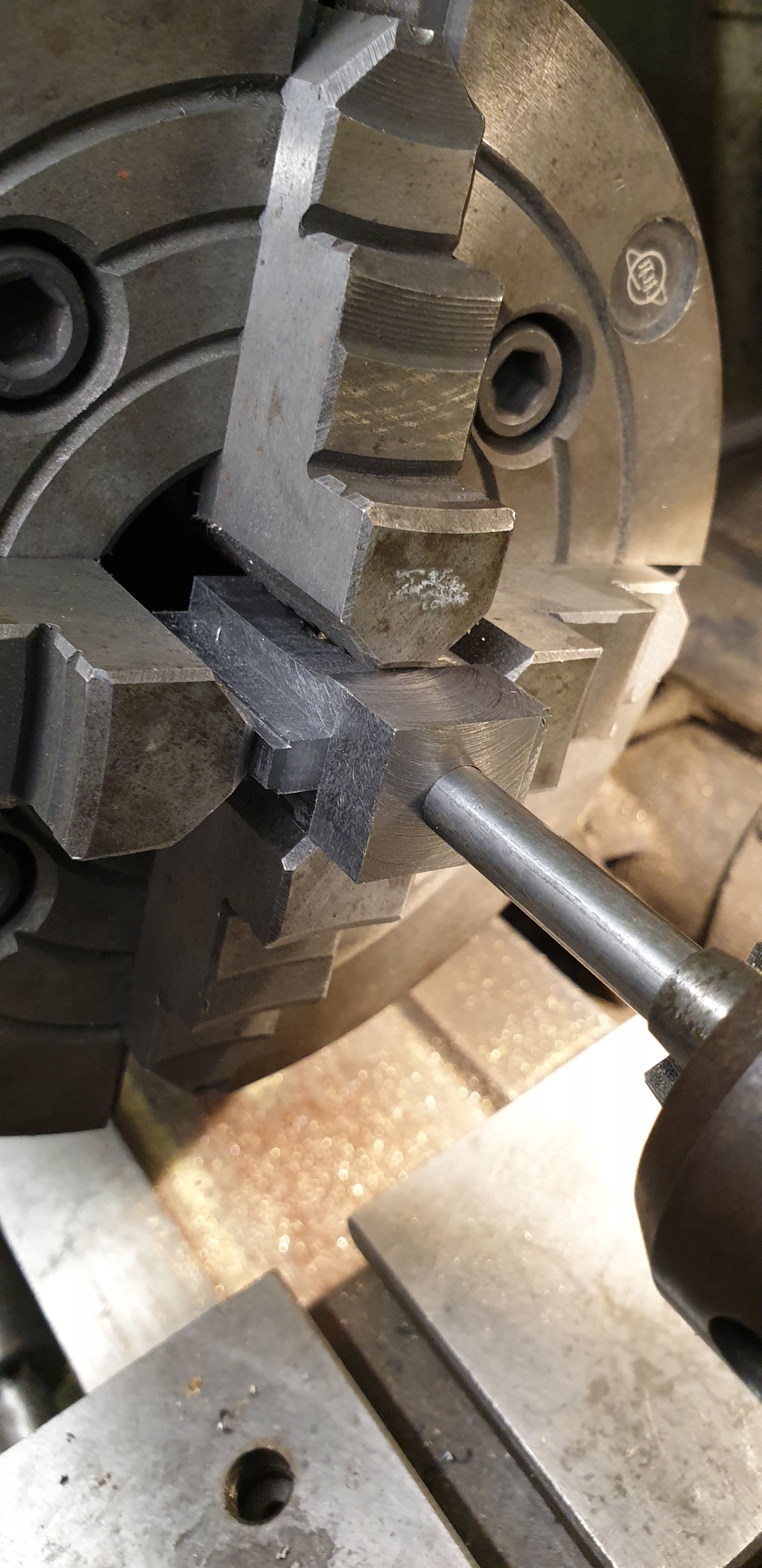
Ok, so over to the lathe and onto the first setup in the 4 jaw, here we can see the second reason for why I have machined the small 5/16 recess into the opening of the rod bore. I don't need to worry about clocking each blank with a DTI, all of the critical dimensions have already been set/determined with the holes accurately drilled and then the blanks tested for fit on the slidebars, we are now just dressing the parts to achieve a prototypical shape.
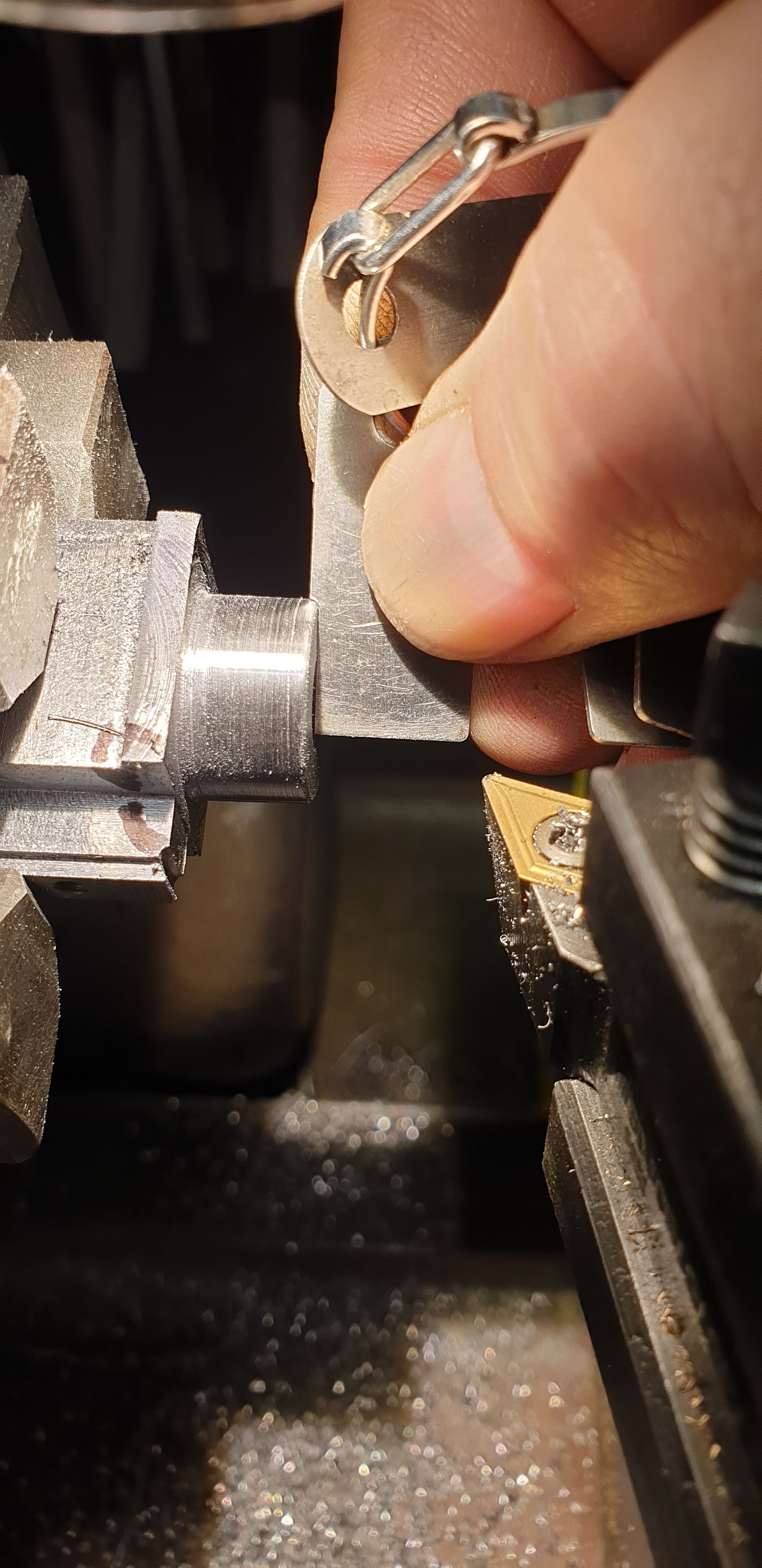
Once I was happy with the part running true I could begin to rough out the shape, to do this I used a 6 mm profile tool, machining in as far as was safe before hitting the slipper pedestal and filed the end to give me a 30 thou rad. I then changed to a normal tool to begin removing some of the excess material but stopped as I decided it wasn't a good idea. The picture shows the rad being checked and where i had begun to machine before stopping. The black outline is a rough guide as to how far I needed to cut into the blank on this (nearest) side (top), the other side (bottom) needs to go much further. BTW, so far I have only cut parallel, I'll need to taper this in later and also cut a recessed step which will require a new tool profiled, more on that when I get there.
I needed to make a tool suitable for the next stage, more on that in a minute but after doing a few passes it was obvious that I was chancing my luck with the amount of excess material around the edges. So I returned to the mill and machined away most of the overhang (corners), this picture shows that I have taken material off both the top and bottom areas and thus squaring things up a little. You can also see where I have begun to machine the profile before returning to the mill.
I did this to all 3 blanks, the second blank seen here to hopefully show what I am trying to describe, as can be seen I did the other two before starting to profile the shape with the tool made for the job.
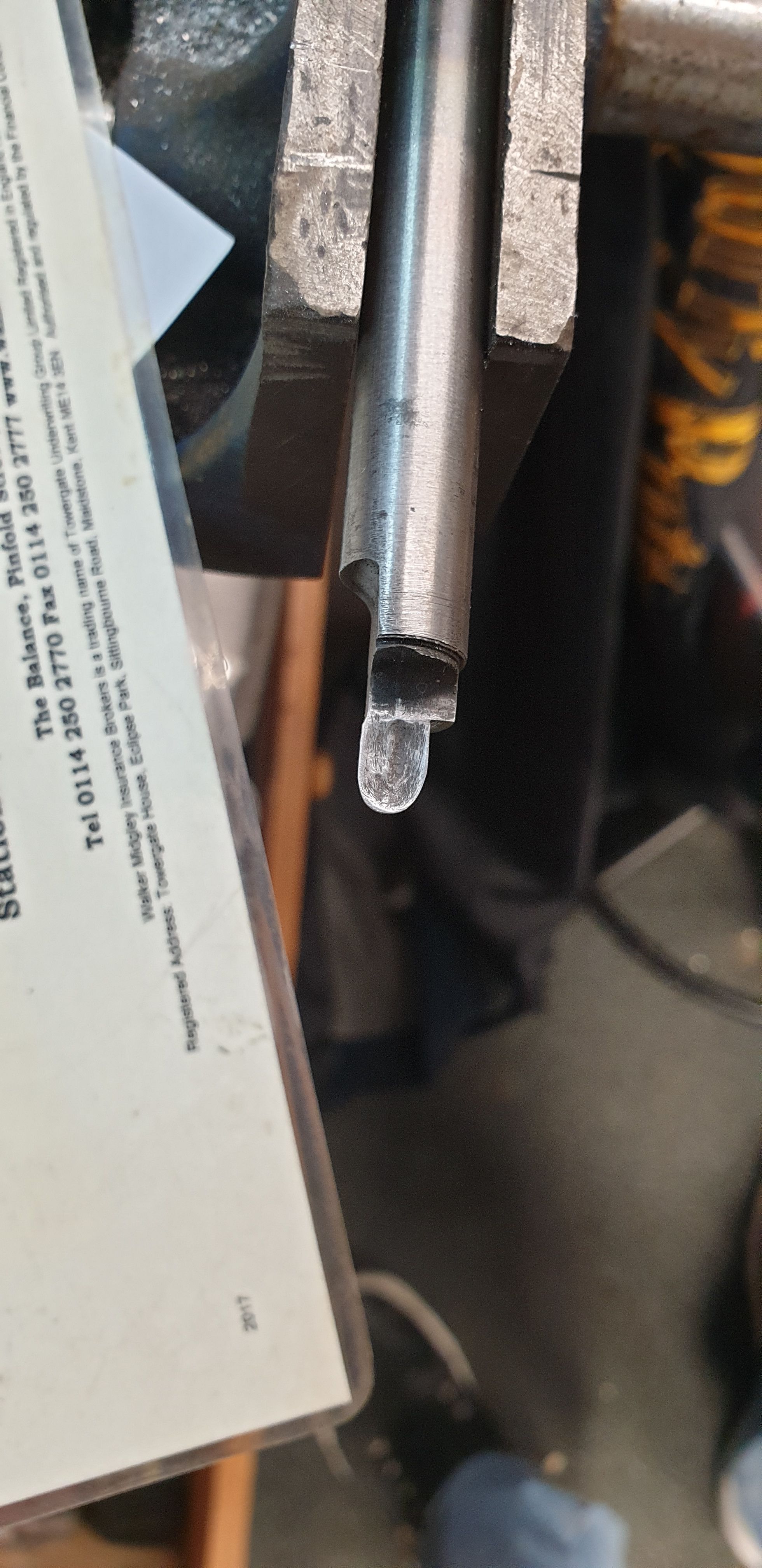
Here's the tool that I am using for this stage, actually this is Mk2, the first was identical in profile but the tip was much longer allowing enough length to cut all the way in to the finished shape. The tip cut very well but wasn't strong enough to take the pounding as it bit into each corner, when I say 'strong'? the tip was fine but the length was inclined to bend down a little, I straightened it, reheated to harden the tip further and tempered best I could without softening the tip but this didn't work as it was now too hard and broke off. So this is mk2, with a much shortened tip that is just deep enough for the overhang of the slipper pedestal and also much stronger as I have beefed up the area directly behind the tip. It has also had one face flattened to clear the end of the crosshead where the piston rod enters. As seen here, the tip has been hardened and sharpened with an oil stone, it is very sharp with a good rake (cut with a Dremel grinding stone) to ease the cut. Material used is silver steel. The tip has been profiled to cut both the round boss on one edge and also the undercut below the slipper on the other edge on the one pass.
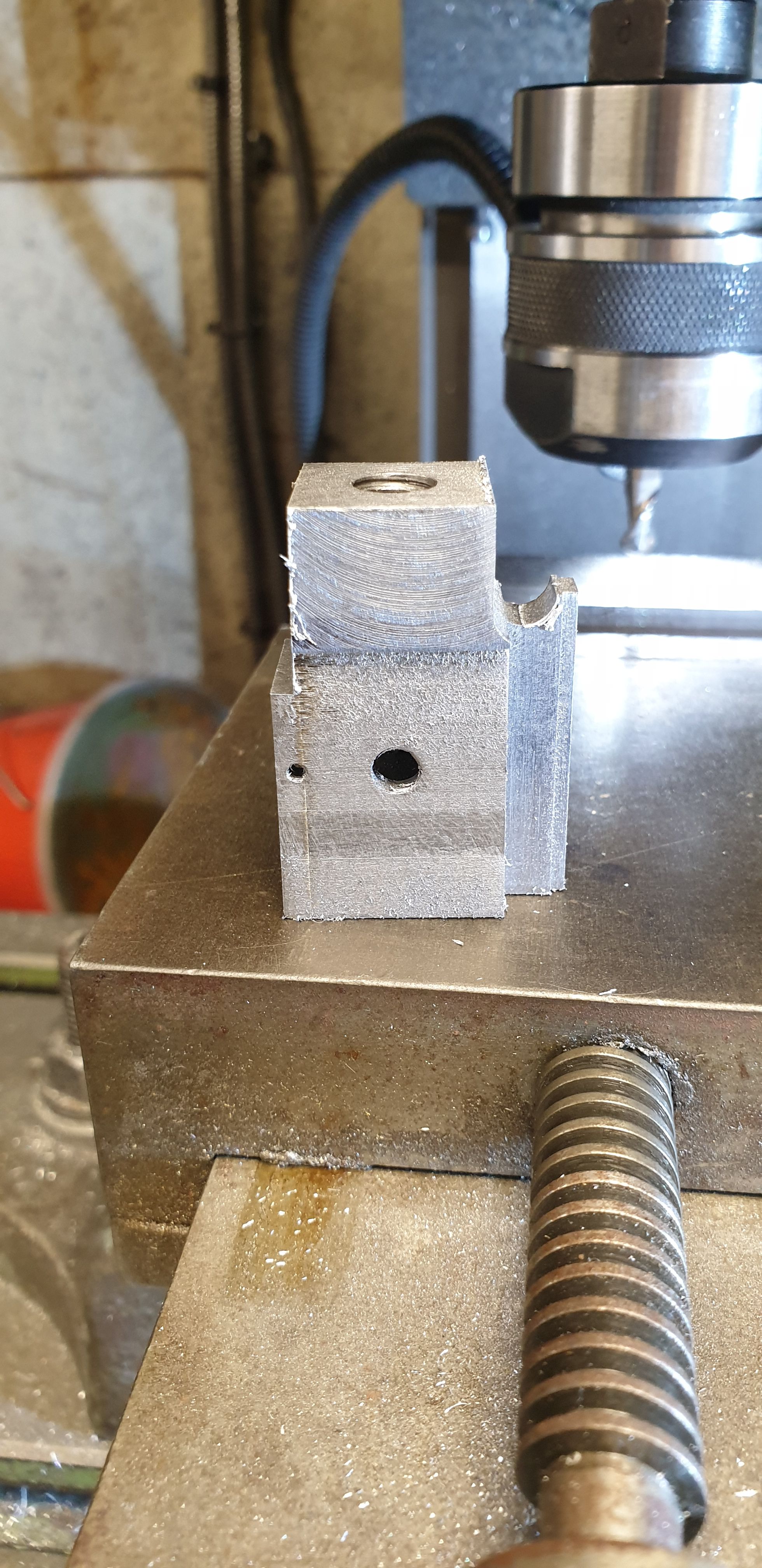
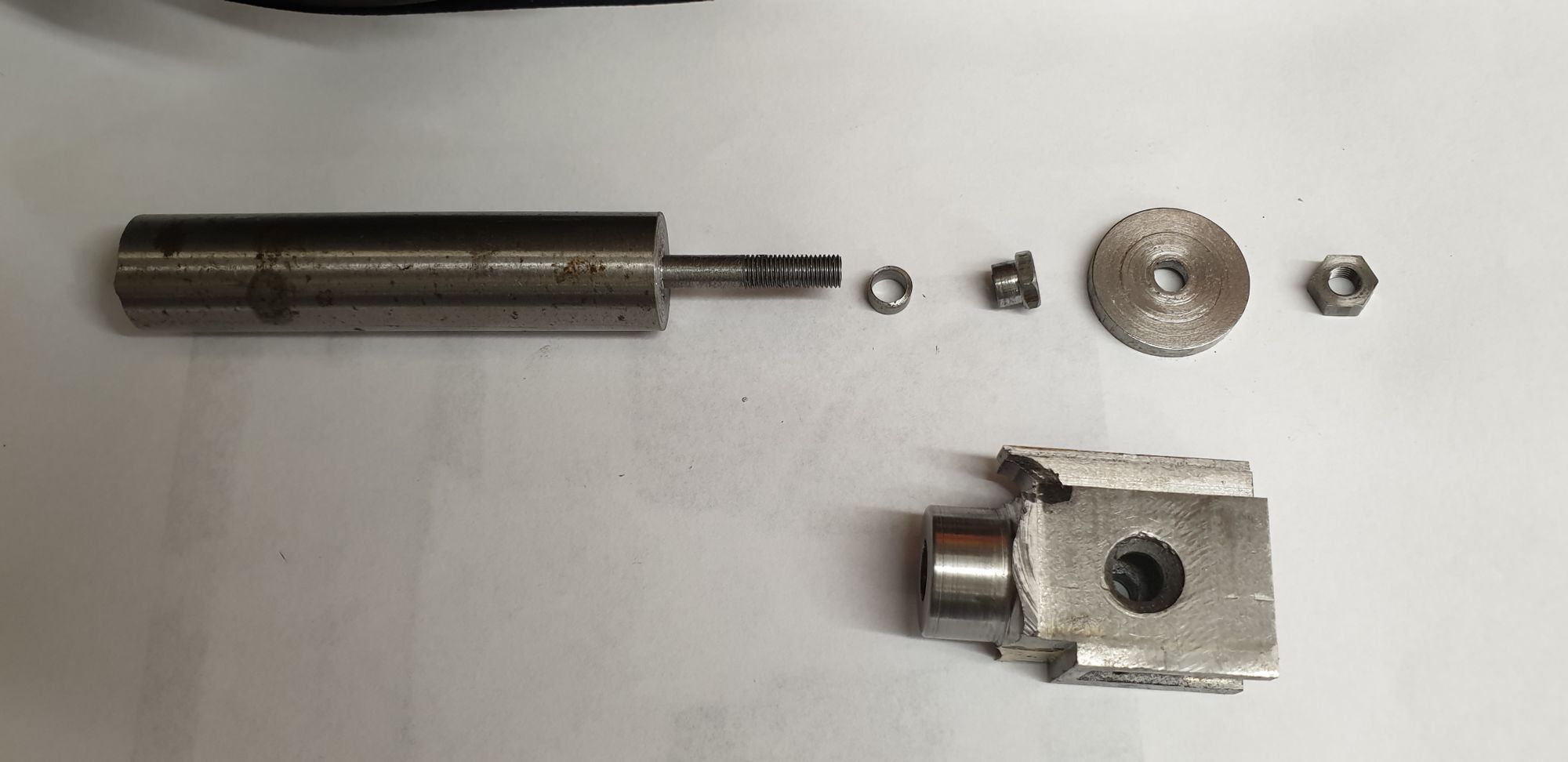
Now, before continuing with the profile tool to machine the rod boss to size I first wanted to both remove some more material from the extremities to give the tool an easier path and also mark the side face to give me some idea of where to stop with the profile tool. For this I would need the rotary table but first needed a jig to hold each crosshead securely. The cross drilled holes are ,of course, two different sizes so I have made some bushes to allow for this. Looking at the picture from left to right, the bar is an offcut of EN8 , left over from when the crank axle was made. I have turned down one end to fit the smaller of the two holes, I then threaded it 3/16 x 40 TPI which just happened to be the closest thread to the size of the spigot. Next we have the 1/4" bush, this is slid on first when machining the side with the smallest hole, next fitted is the large button which is to a size which gives a small step between the body and the drop arm mount (this will become clearer later) and finally a nut to lock everything down. When machining the side with the large CSK hole (seen in the picture) the first 1/4" bush is removed, the next bush seen in the picture (also 1/4" OD but with a lip which has been filed to give a chamfer to locate in the CSK hole) has been designed to fit the CSK hole after the crosshead is sitting on the jig, followed by the button which has a machined recess on the underside ( not seen here) to fit over this bush and then locked down with the nut. Hope that makes sense, the end result is that the crosshead is held securely for both sides to be machined with this one jig.
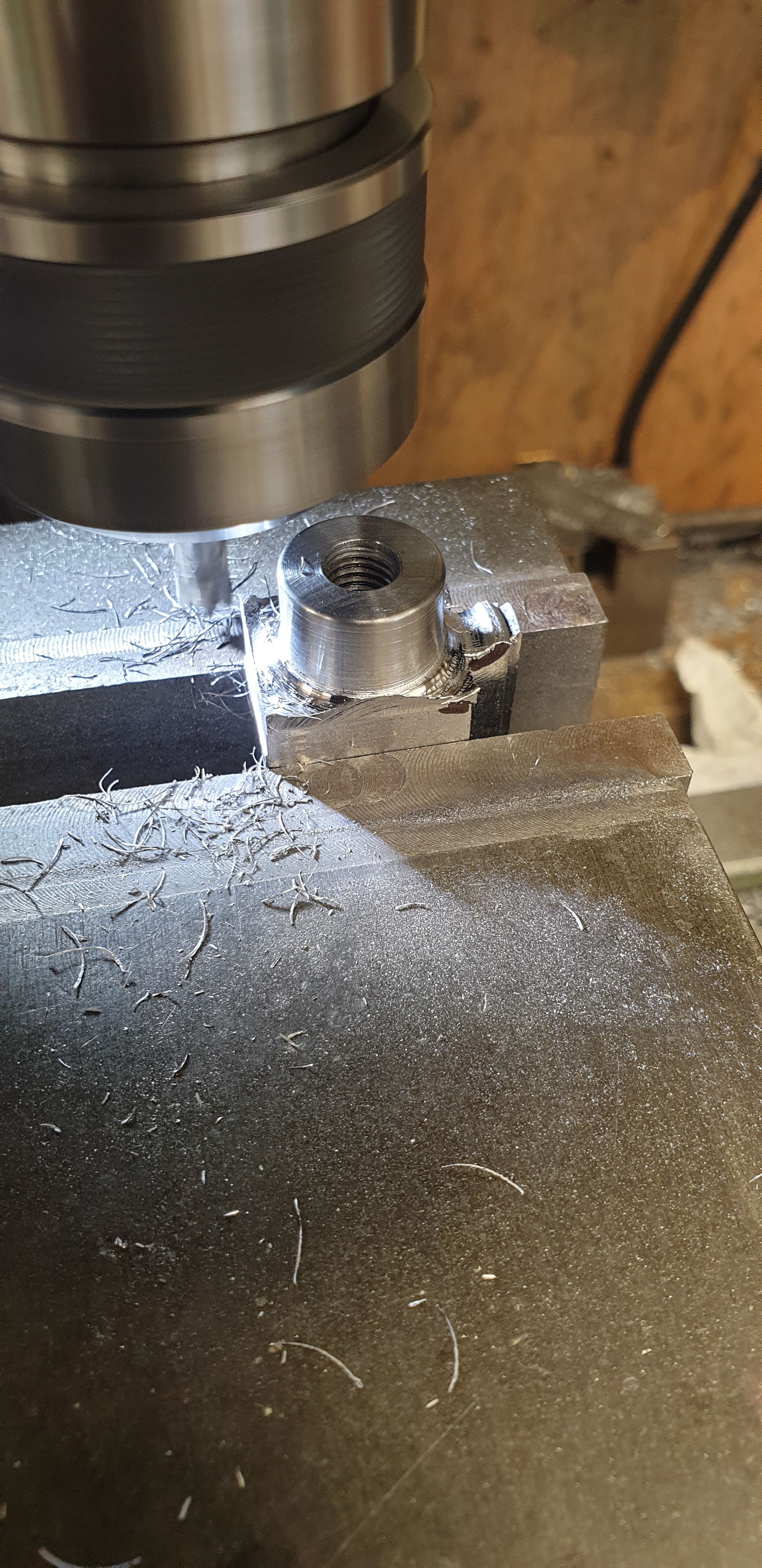
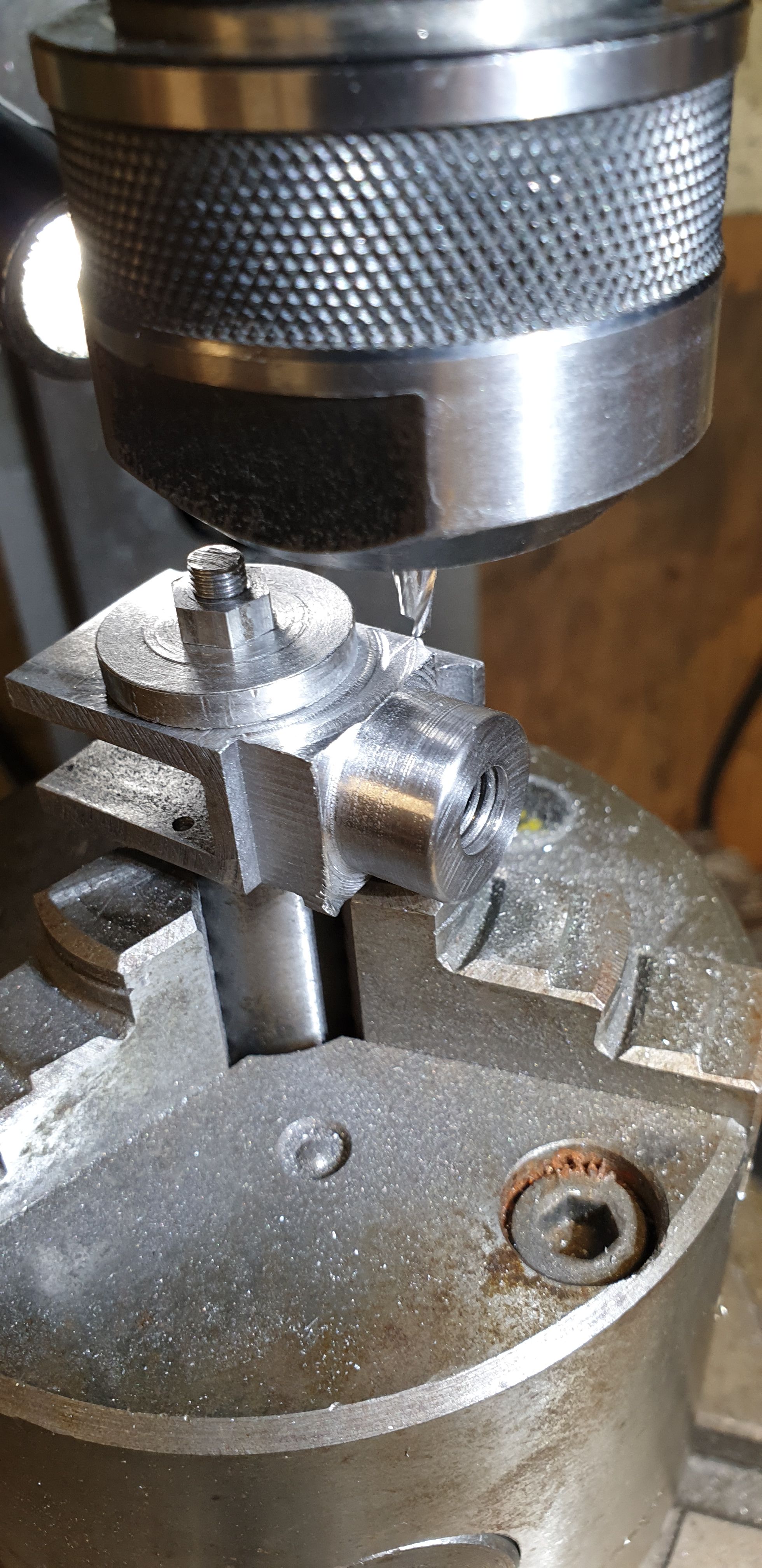
With this all set up on the rotary table I could begin machining the side face down to roughly meet the round section already machined. This is very much still in a roughing out stage. The picture shows that one side has now been roughed out which is where I got to for tonight. Once all three have been so dealt with, I'll then use a ballnose cutter to remove as much of the access material as possibly, we are talking of the sharp corner still evident in the picture, once most of this has been removed I can return to the 4 jaw with the profile tool to finish the rounded section down to where it meets the sides. This will be tapered, there is a short parallel section ( 7/64) at the front of this part and from there to where it meets the main body is tapered just over 2.5 degrees which will then step up (concave) to the body side. There will be a further step but this will be part of the drop arm mounting plate. Oh and just to add to the fun, the tapered section has a further step in which is rounded at the front and squared at the back, this will, again, become clearer when I get there.
Well that's 3 parts so far, I suspect that there will be a good few more yet...:)