

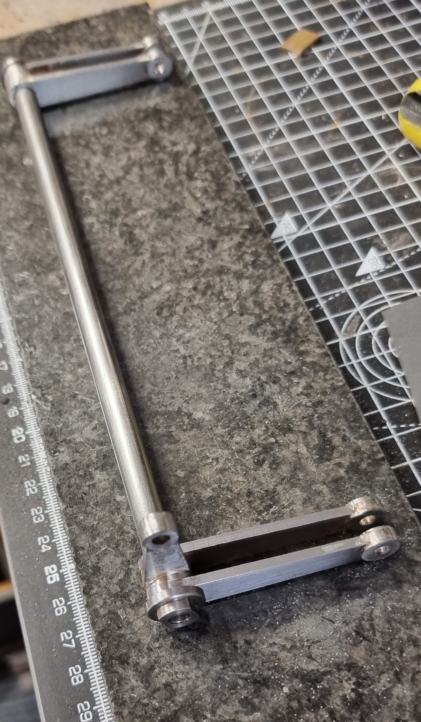
This entry sees the completion of the radius rods, the lifting arms and the sliding blocks connecting the two. I have to say that i have been making up these various components and only when assembling has been done did I appreciate how there is no room for error here, the pictures attached will show what I mean.
The first job was to check the fit of the radius rods on the model, before doing this I made up the sliding blocks which alas I forgot to take a picture off.
Here we see the left hand radius rod fitted.
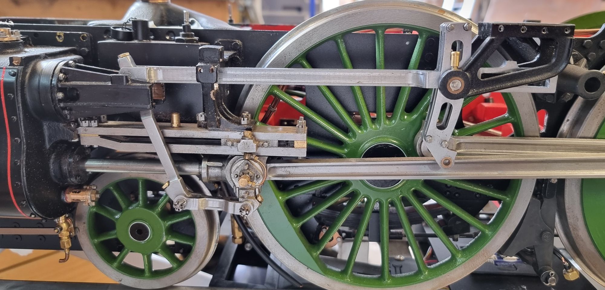
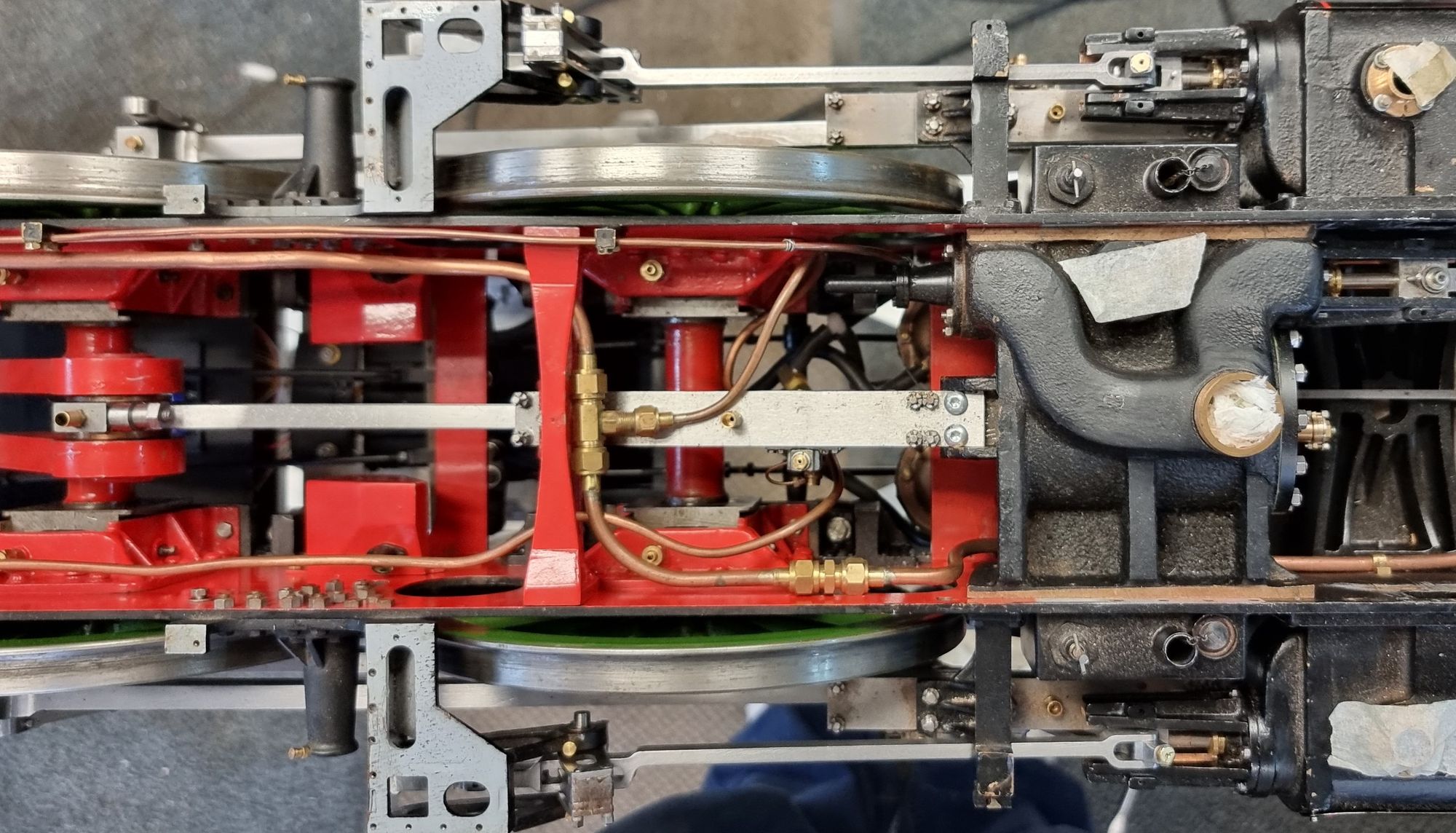
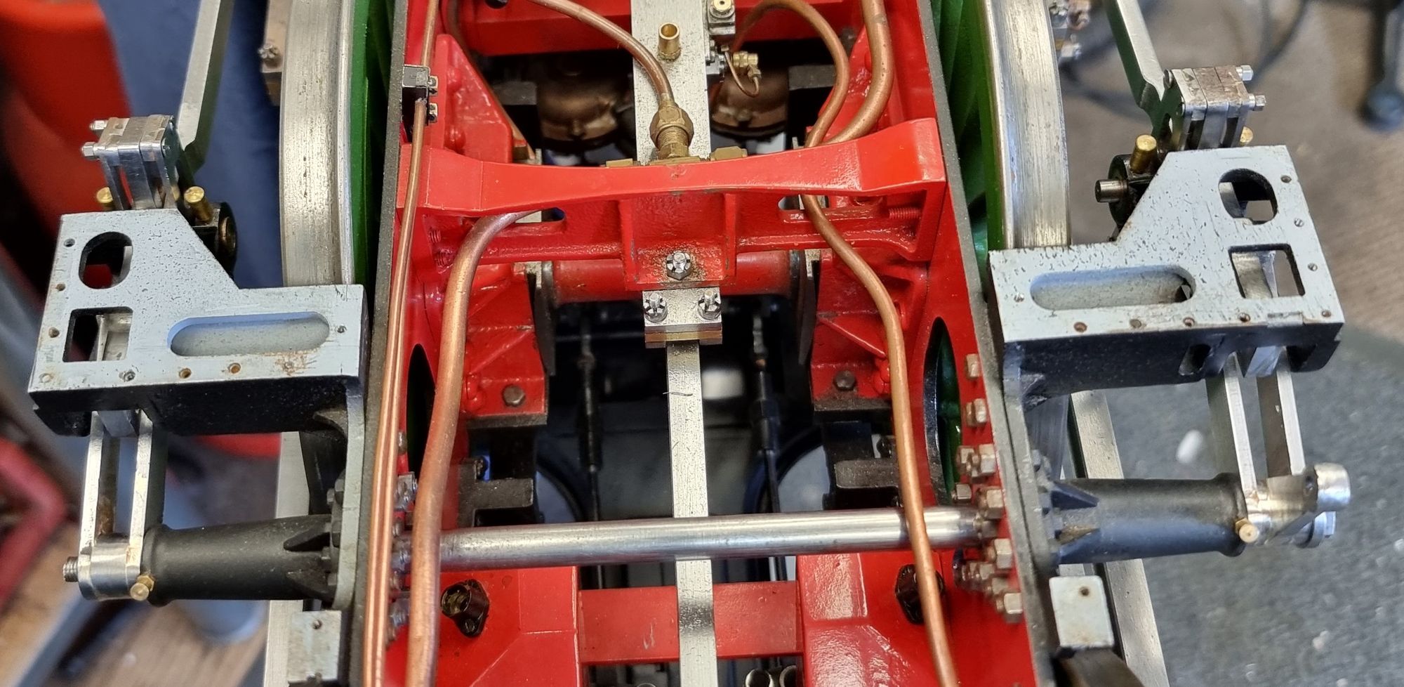
I view from above showing both rods now fitted and they are running parallel which is good to see after deviating from Don's drawing and making the rods more prototypical in the important (it's visible) area around the expansion link.
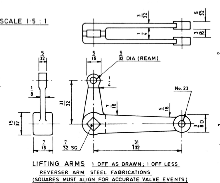
With the radius rods fitted I then turned my attention to the lifting arms, to aid in building I had the basic shapes laser cut to save time, my thanks go to Ed (Model Engineers Laser) for his quick turnaround. Here is Don's drawing for the arms.
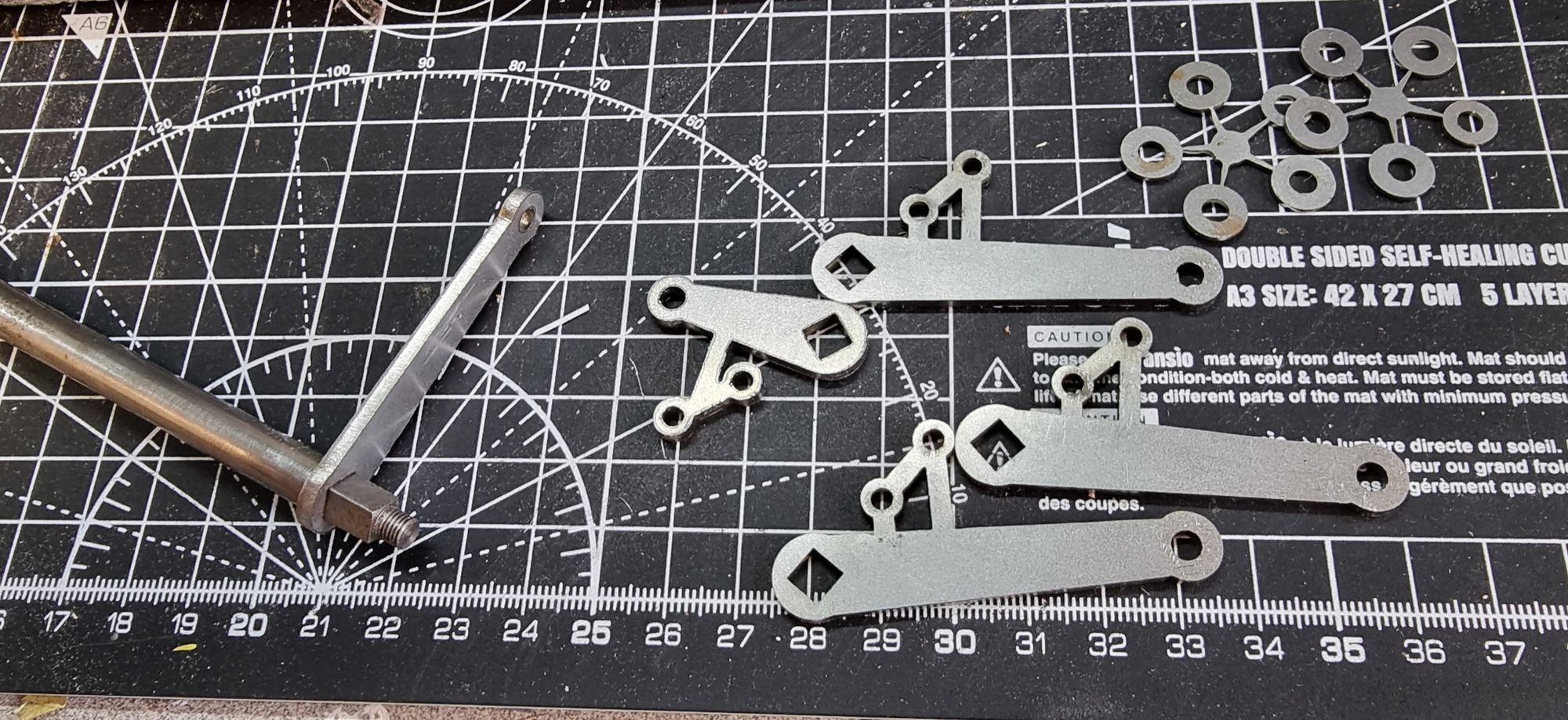
And here are the laser-cut parts from MEL, Note that one arm has been test fitted to the weighshaft, I asked Ed to make the squares a fraction smaller so that I could ensure a good tight fit. Other parts needed were a 1/4 wide collar for the left-hand arm and two smaller collars for the right-hand side which includes the 90-degree arm for the reach rod. These were simple turning exercises on the lathe.
I won't give a breakdown of the silver soldering operations here as it's all the same as before but will show the finished arms attached to the weigh shaft. Note also the end caps fitted, I cheated here and used the spare caps from the crank pins. They are different threads, the crank pins being 7/32 and the weigh shaft being 3/16, but with a little pre-thought I modified the caps to fit. To do this I first threaded a length of 7/32 steel in the lathe, centred and drilled a 3.5mm hole deep enough for both caps plus parting clearance. I then in turn, loctited each cap to this, drilled the clearance hole 3.9 mm for tapping to 3/16 x 40 TPI and parted off. This worked very well and thus saved time as it only took minutes. The important thing here was to get both arms in the same position which I'm happy to report is how things are.
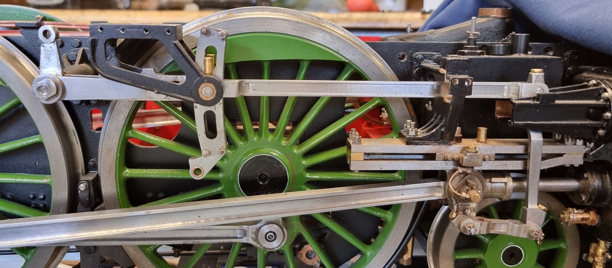
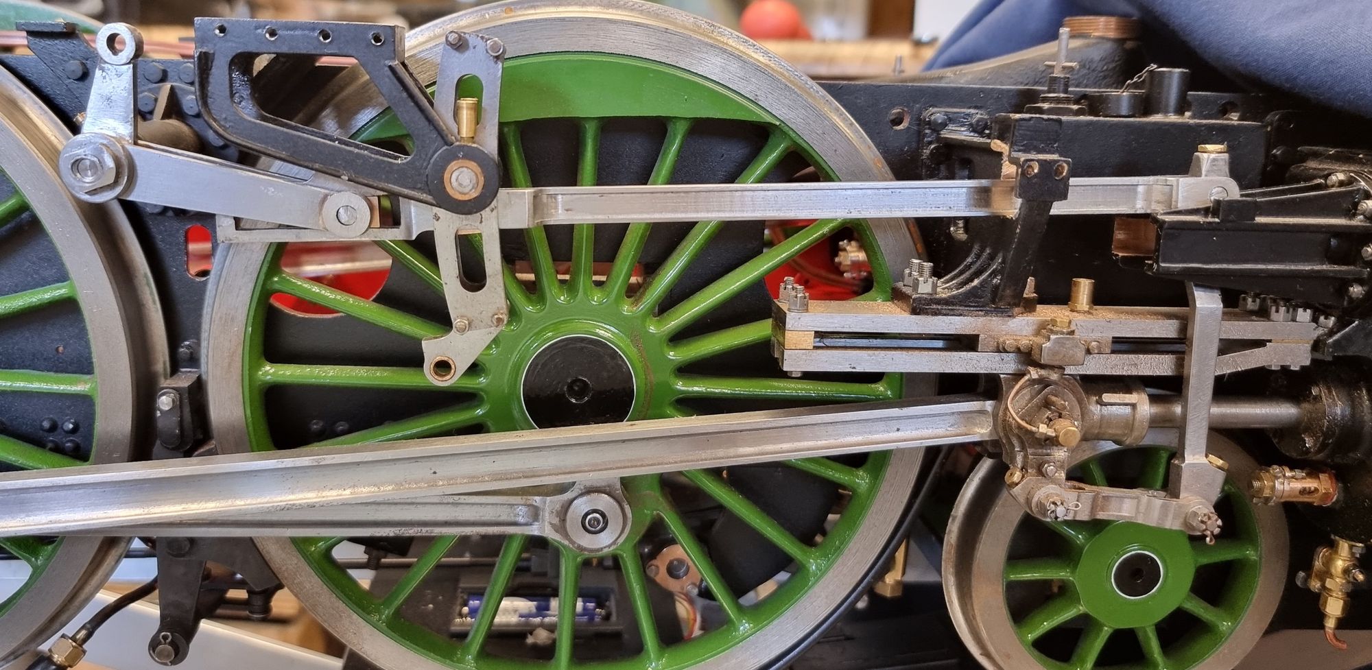
I then assembled the weigh shaft with the lifting arms and their sliding blocks to the model, no unforeseen problems but it is a fiddley job getting both sides inline for their pins to be inserted. It was while doing this part that it dawned on me just how critical all these parts are as there is 'zero' tolerance here. The weigh shaft has to be the correct length and the arms also needed to be correct for them to not only fit on the shaft biut also fit around the radius rods and in between the expansion link bracket, I am so glad that this worked out as it should with no changes required.
The final 3 pictures just to show the lifting arms in their furthest positions. I can't really tell if there's enough movement until the rest of the valve gear is assembled but there is more than enough room for the sliding block in the radius rod to do its job. What may need my attention is the R/H side outside motion bracket which may need a little removed from the bottom of the opening to give more clearance for the rod. I have already opened these up much more than don has drawn as his slots were impossibly small for the rod to fit. I used photo's of SNG as a guide here, the photo's shown in the overhaul of the loco show much larger slots, larger still than what I have done and from which I may well follow in due course.
Mid gear
Reverse gear
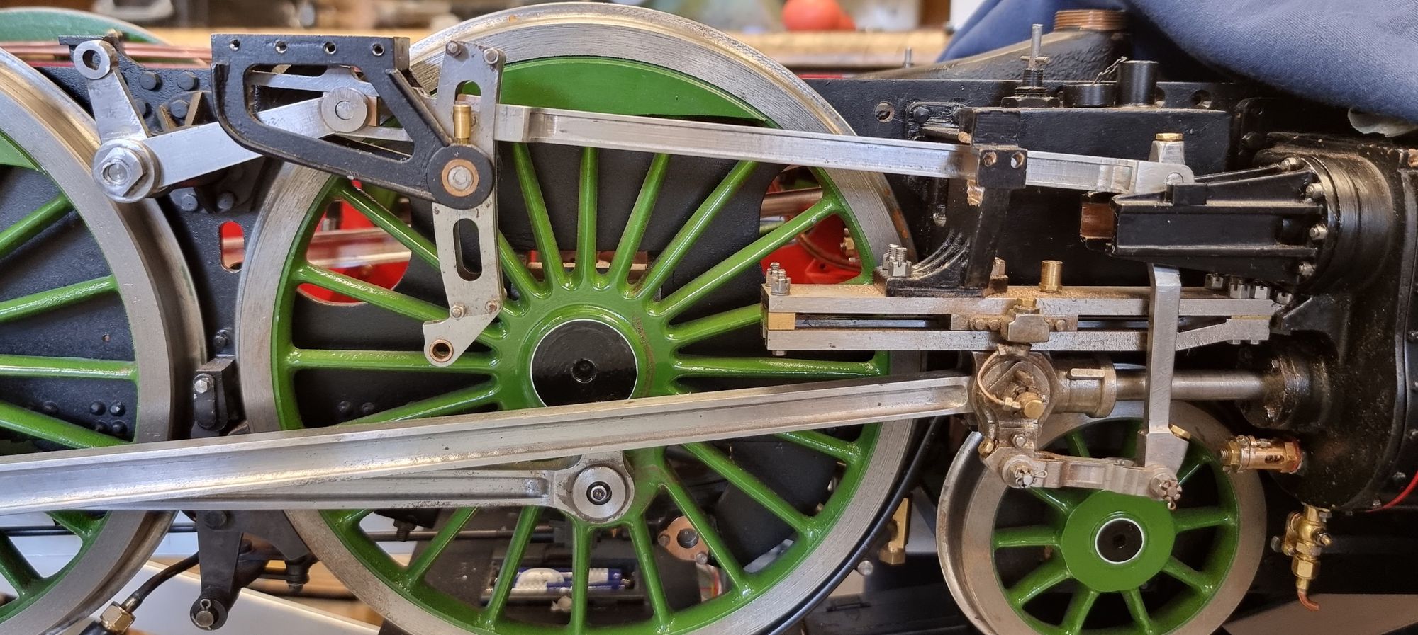
Forward gear, this is when the rod is touching the bottom of the outside bracket and thus reducing the movement as can be seen here.
I'll leave this section for now, I won't fit the proper lifting arm pins until the rest of the motion is completed. I say the 'rest' when in fact I only have the eccentric rods left to make to complete the valve gear. I'll make up a couple of dummies first to check all is correct before spending the time involved on making the proper rods. I also need to source some spherical bearings for the connection to the return crank. I also need to fit the valves which are already made and then do the timing, fun times ahead.