

The ashpan is one of those parts that need to be made to fit both the area between the frames and the shape of the foundation ring, Don says as much but also says that if all other parts are to the drawing then what he has drawn should be a perfect fit.
with this, in mind, I felt confident that the basic shape could be made as per the drawing, where it differs is in the area around the foundation ring. I say 'differ', there's not that much difference but the possibility of things being different had to be considered. Now I say all this even though once again I relied on John Baguley's excellent CAD drawing experience so that the various stainless steel parts could be laser cut by Model Engineers Laser which is now under Ed Parrott's excellent stewardship.
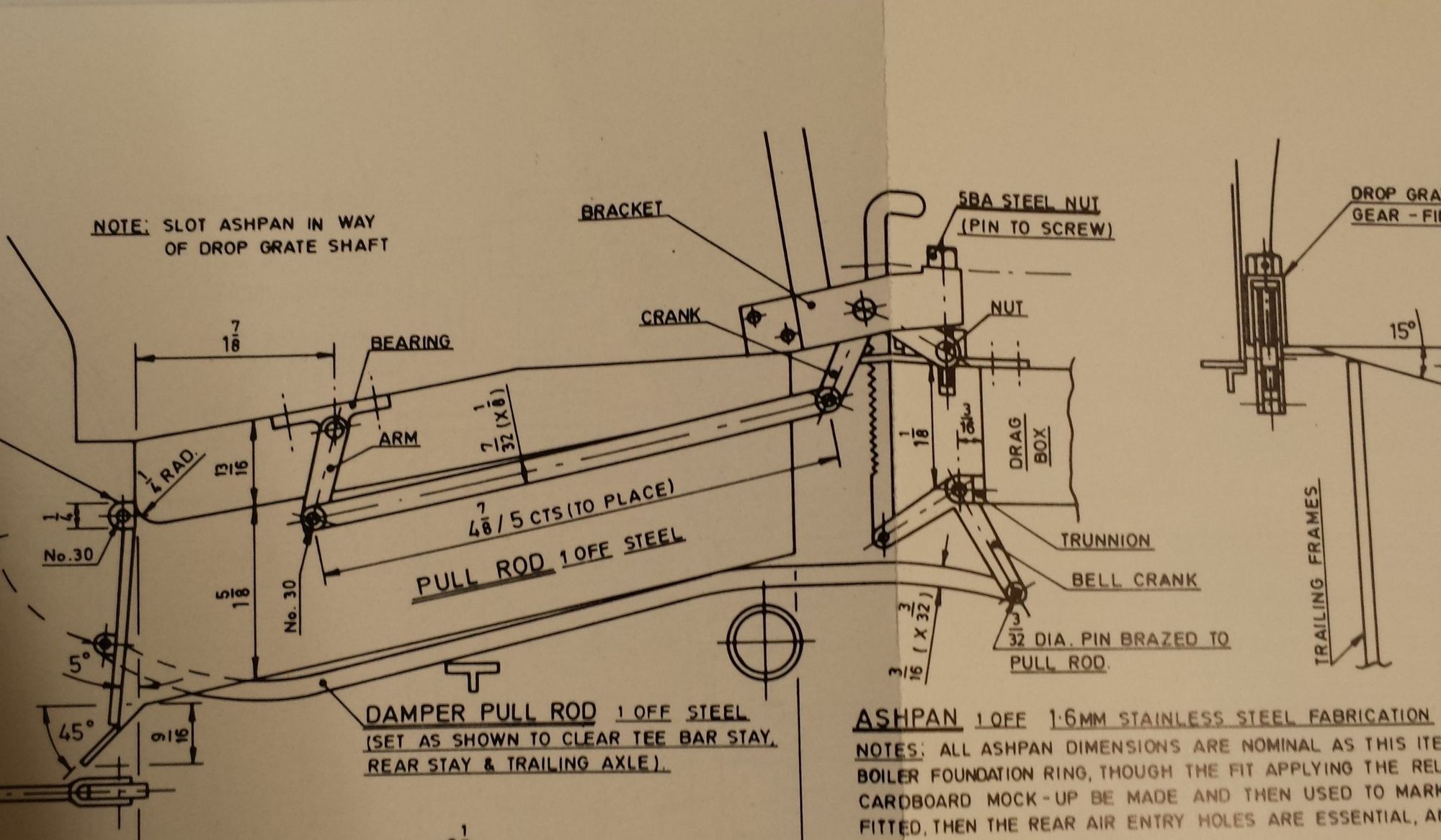
With the background explained, let's now get down to the job in hand, first up a sample of Don's drawing, there is more to it than this but this is perhaps the best part of explaining the design to put on paper. An early decision taken deviating from the drawing was to include a foundation ring plate as per full size, more on this later. As can be seen, there is a lot going on with this ashpan, for this entry I'll just cover the construction and test fitting of the ashpan itself, the damper and drop grate mechanism will be tackled in a later post.
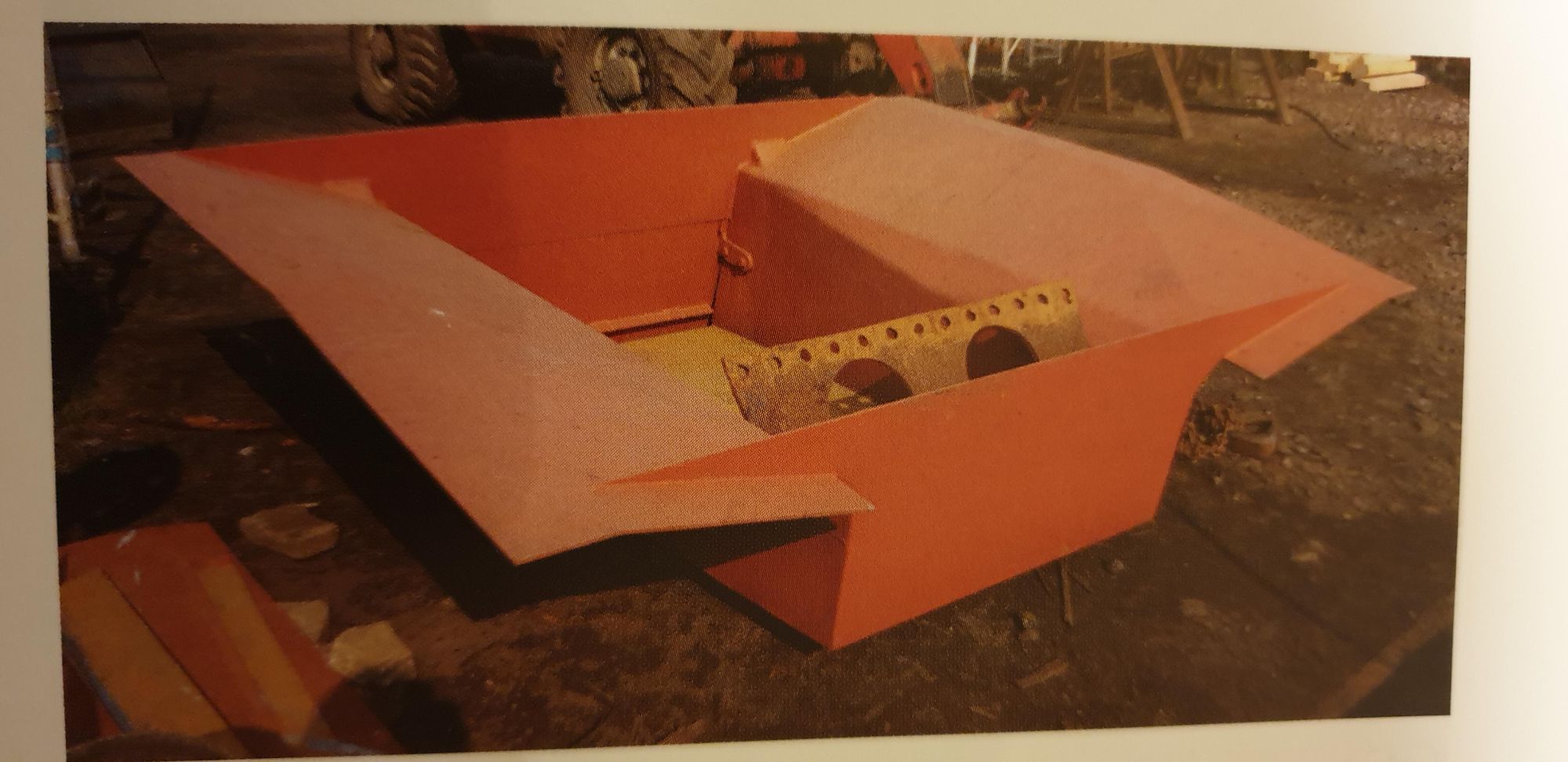
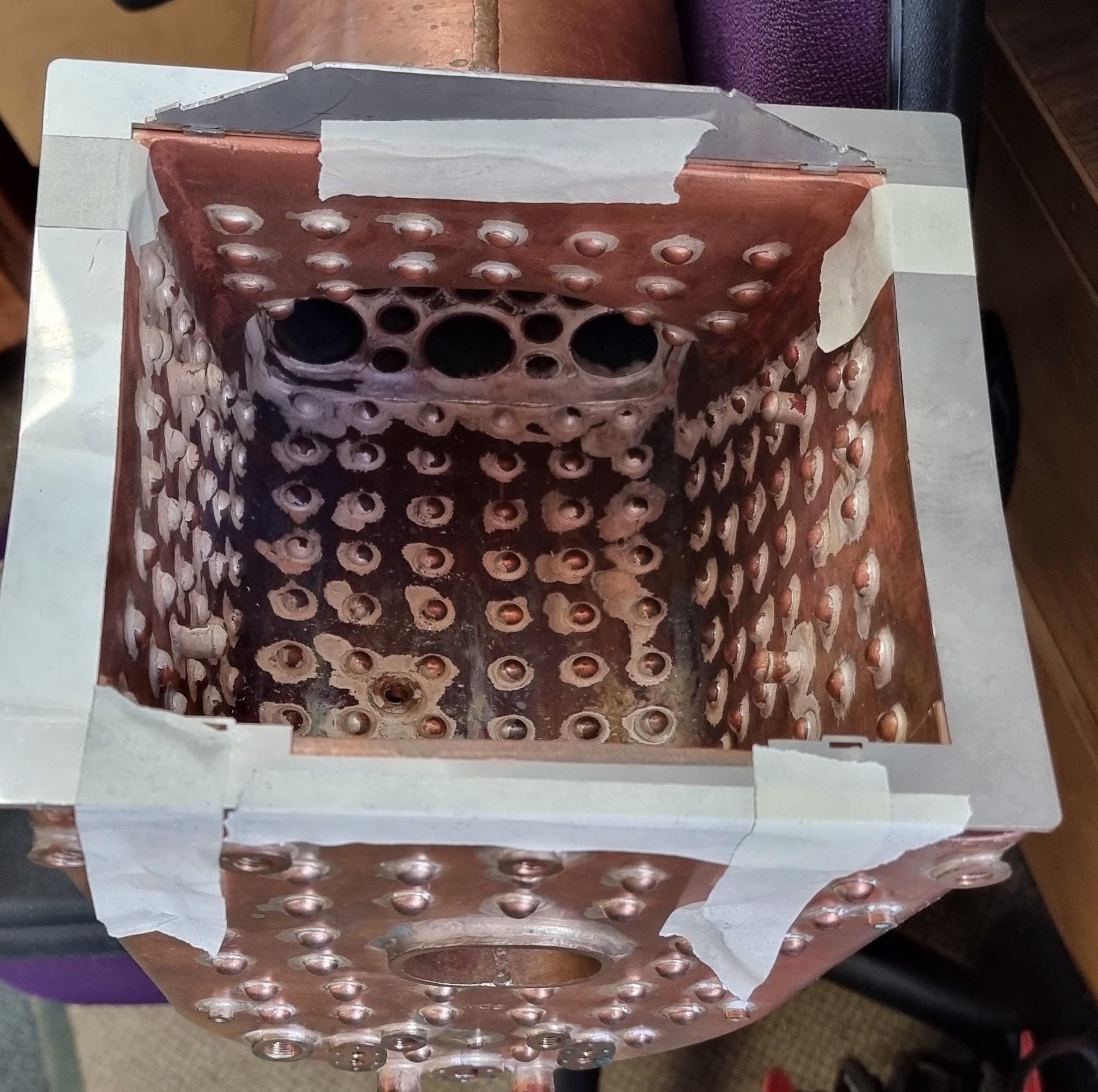
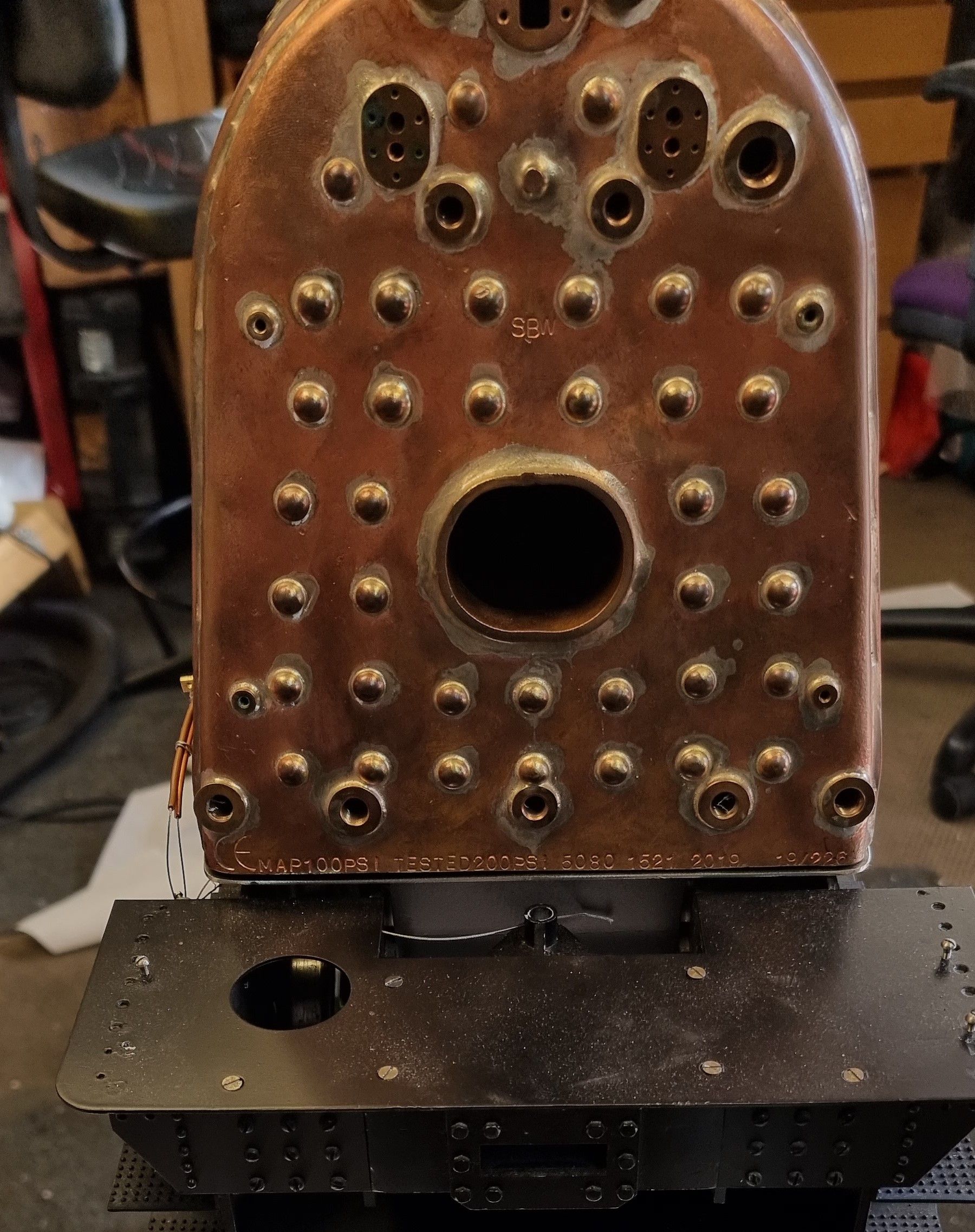
a few pictures of the full-size ashpan might be wise to include here, first a general view from the top. In this case, it's the new ashpan prior to the first fitting, this can be told by the absence of any mounting holes.
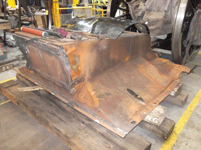
This is a good picture of the old ashpan to show the basic shape which fits between the frames, it also gives a good view of the damper door. Note the elongated slots, I haven't been as neat with mine but the principle is the same to help align the pan correctly.
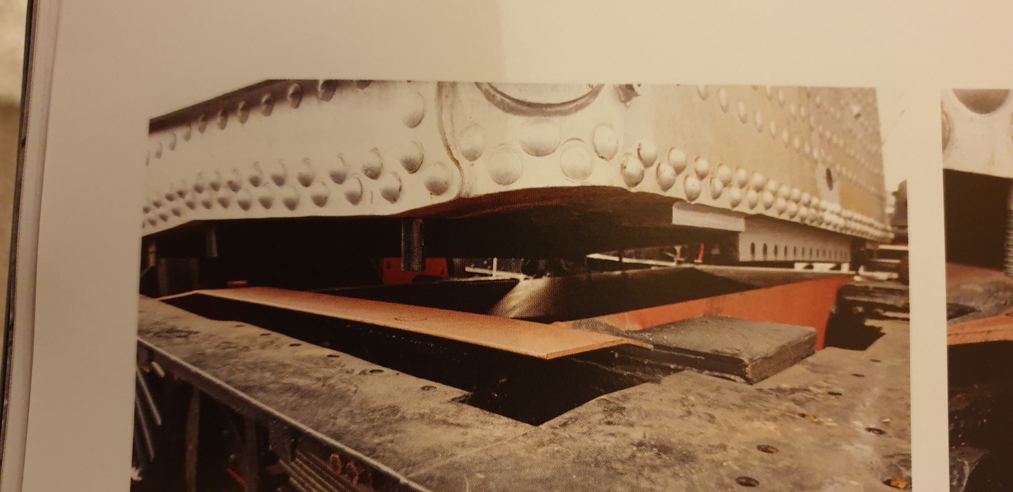
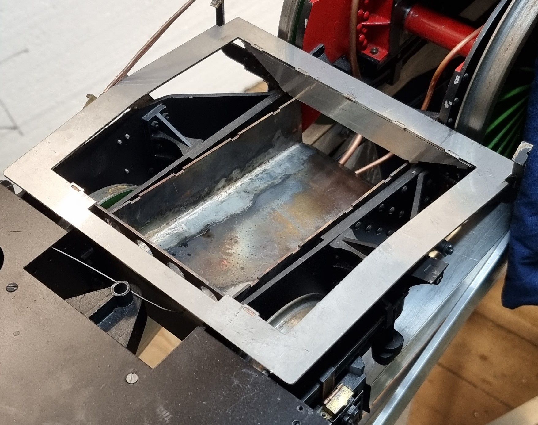
Here we see the new ashpan in place between the frames with the boiler suspended above for the holes to be marked. Note the studs and in one case a corresponding circle is drawn in black on the foundation ring plate ready for drilling.
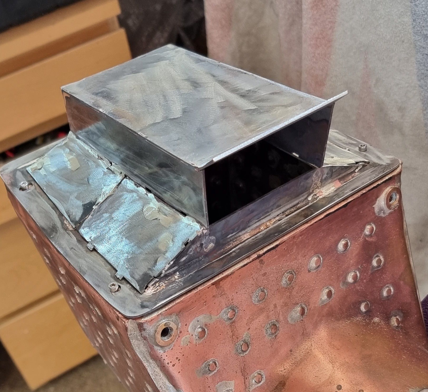
Back to the model, John worked very hard on the CAD work which as per usual was excellent. Most of the dimensions where taken directly from Don's drawing, exceptions are, I asked for the width to be slightly less, IIRC approx 1/8" as I wasn't entirely sure on how much clearance there would be for the damper rods, I think this may prove to be a prudent move when in service. Anyway, John did an excellent job and provided me with the drawings for me to print off and then cut out of 1.5mm styrene to make a mockup for testing the fit. The foundation ring plate was worked out by me drawing up a template from the boiler foundation ring and sending it to John to be converted to CAD. The photo shows the mock-up in place, After this, I asked John to add 1mm more around the outside edge of the foundation plate to ensure that it covered the boiler ring and thus give me the fixing points required. You may recall that the boiler had 3mm holes drilled/tapped into its foundation ring for the pan to bolt to.
With the design proven, the drawings were sent to Ed for cutting and these are the parts as delivered. Something to point out here is the four holes in the rear plate. Don states that these are required if no arch is fitted and that the holes can be continued through the rear stay which sits just behind this plate. As noted in the past my boiler will be fitted with an arch and for now, I will leave out the continuing of the holes through the rear stay until a little more study has been done on the drafting of primary secondary air for a Gresley A1.
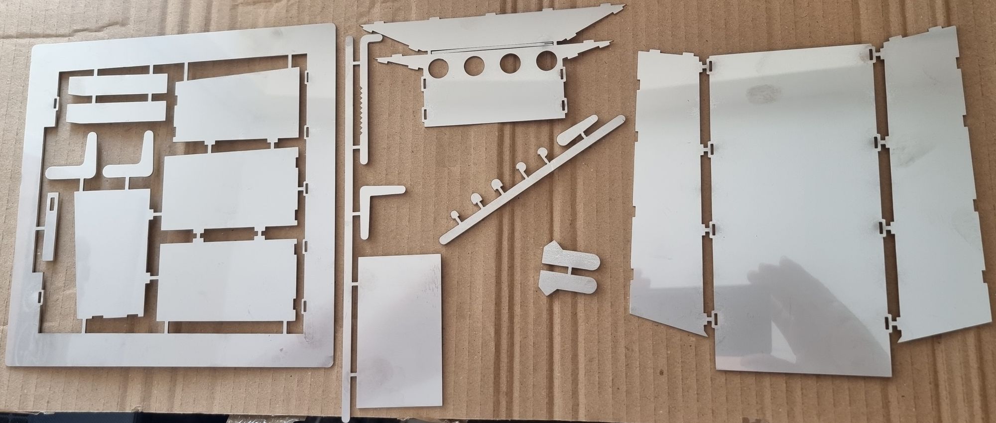
When the parts arrived, I couldn't resist doing a dry assembly, this took but minutes and looks great.
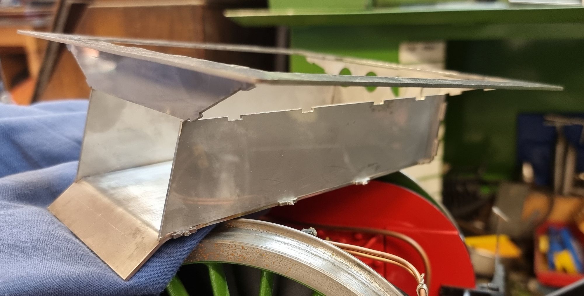
With the pan assembled I then wanted to check it with the model, I didn't actually insert the pan into the gap as it still had the taps on which would have damaged the paint, but at least this gave me a good idea of where we are.
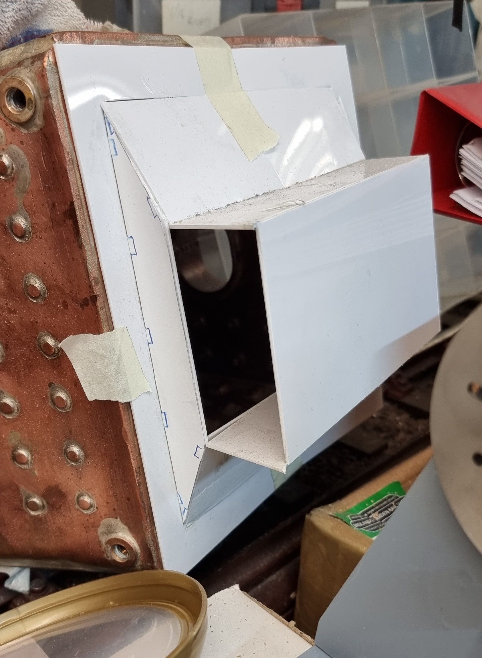
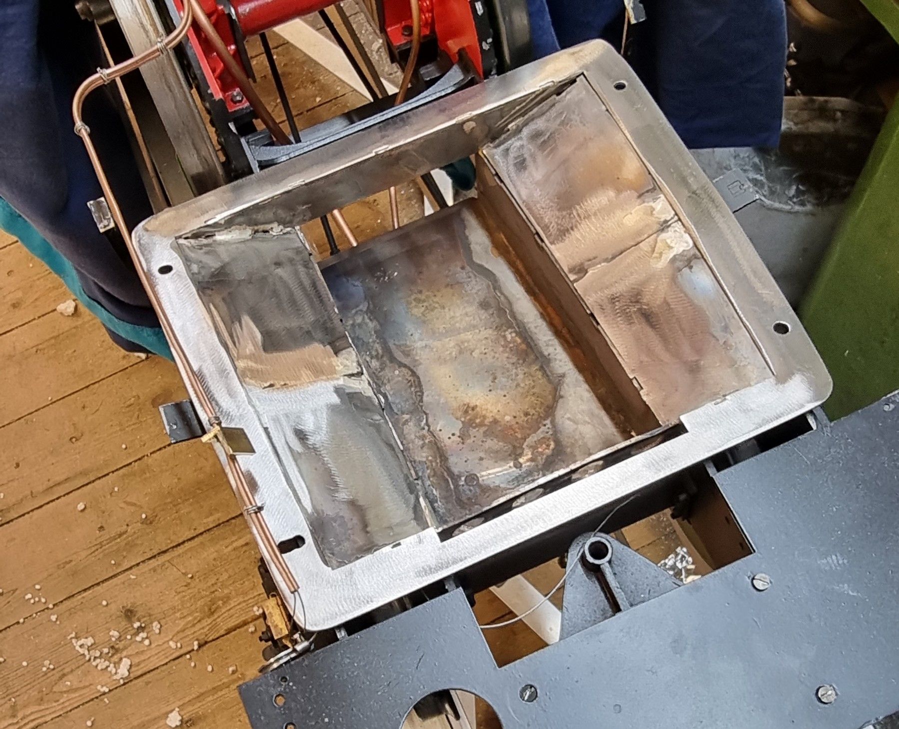
The next job was to form the ring plate over the boiler foundation ring. I did this simply by taping it in place and tapping it with a rubber mallet until it sat flat on the foundation ring. This went much smoother than I had expected.
Once that was formed I silver soldered the pan together, trimmed off the slot/tabs and placed it between the frames. Next was to place the newly formed ring plate over the pan to see how it lined up, I have to have that I was very relieved to find that it was made for the job, well done John.
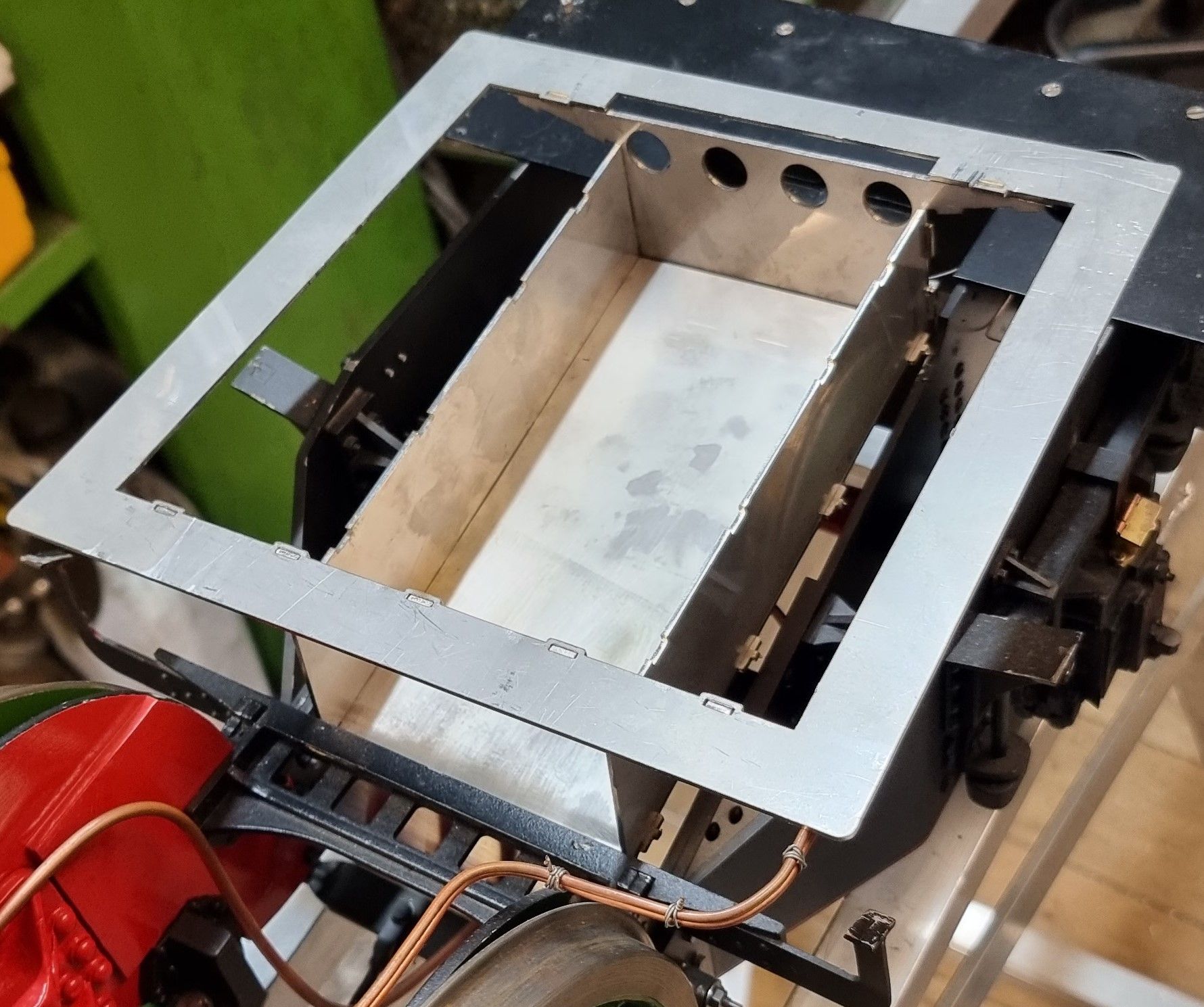
It was then time to fit the ring plate to the boiler itself, this was much easier to do on a model as all I needed to do was invert the boiler, lay the pan on it and mark out roughly where the studs will be. I made the holes larger than required and also elongated them a little to make alignment easier. In the picture we can see that the pan is now bolted to the boiler, these are temporary bolts which will later be changed to studs. Also note that the wings have been partially silver soldered in place, not easy to see but they required a little bit of forming to get to sit in place, I also didn't follow their intended fitment and actually used the tabs as a guide to hold them in place ready for soldering. Also, note that I haven't quite finished the silver soldering stage, alas I ran out of silver solder and thus relied on a tacking process for now. I have also trimmed the edges a little to match the foundation ring.
Now, so far I have relied on the fit to the boiler itself and although did check, take measurements and recheck the final position required to fit the chassis it was still an unknown as to how successful this would be until the pan was actually fitted. I first removed the assembly from the boiler and checked for its fit on the chassis. The fit is perfect, perhaps too perfect as there is very little wriggle room which is a bit boarding for when the pan is bolted to the boiler and then lowered as one piece.
Not wanting to put it off any longer I got some help from the apprentice, ie my wife Sheila and boldly went into the unknown. Or should I say, I bolted the ashpan back to the boiler and with my wife's help lifted the boiler by hand and moved to the model while holding my breath, well not for too long you understand as lifting this thing is far too much for us old fogies. I did remember my duty though and took the heavy end, ie firebox, to save my wife a little from this massive weight. Before I forget, prior to this I first placed the saddle in its correct position ready to support the weight at the front, this also gave a visual aide to the boiler's proper position fore/aft.
I have to say that I was amazed that the thing actually fitted, I was expecting to do a little fettling as there is very little clearance room but it just went in as if made for the job, well it is but even so, this was no mean task. I had already noted that the pan needed to go in with a slight forward angle for the damper opening ramp to slide in place over the rear brake beam and under the boiler stay and wasn't sure if the boiler would foul the saddle because of the angle.
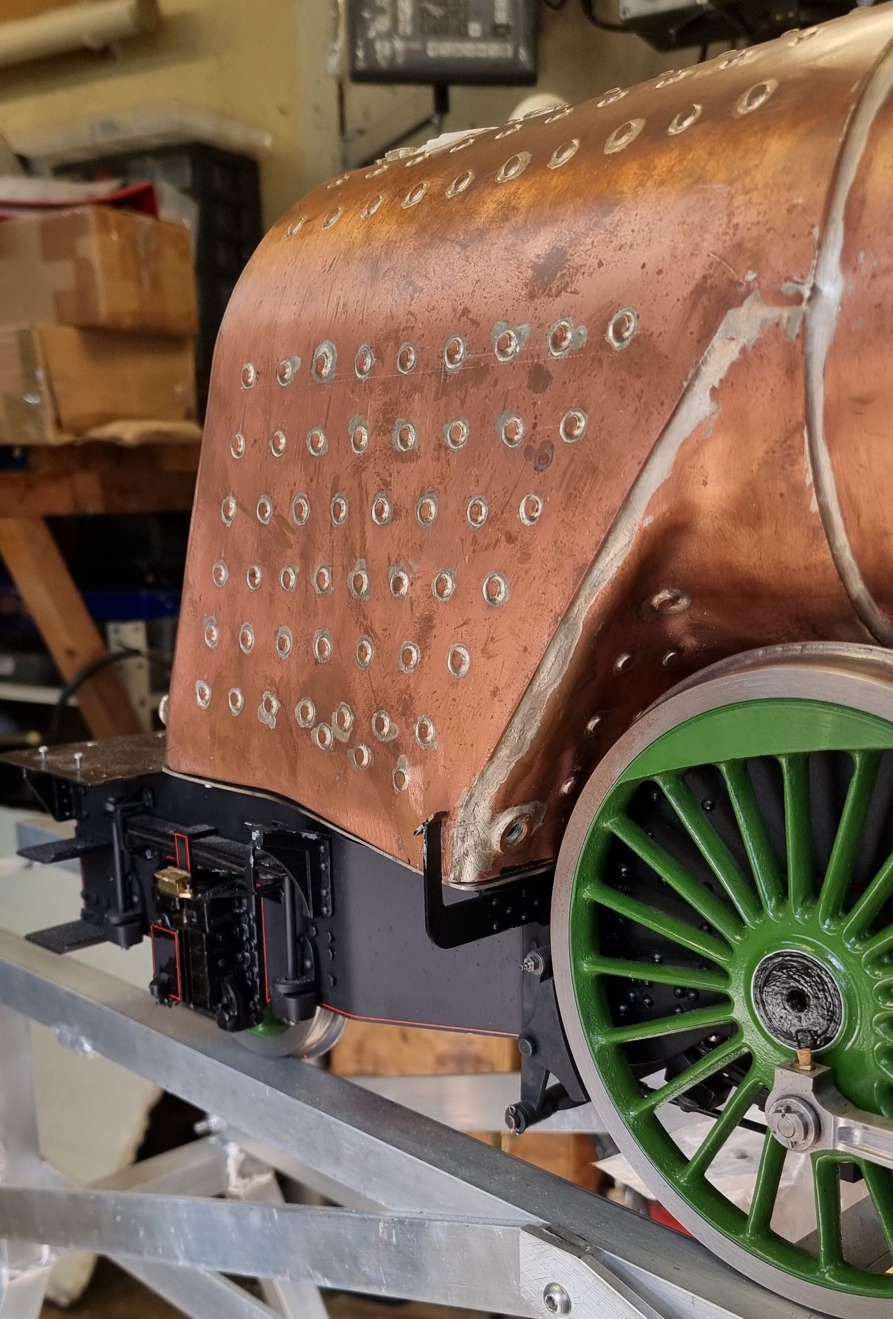
It didn't and all is well, a few pictures to show the boiler in place with the ashpan fitted.
From the backhead...
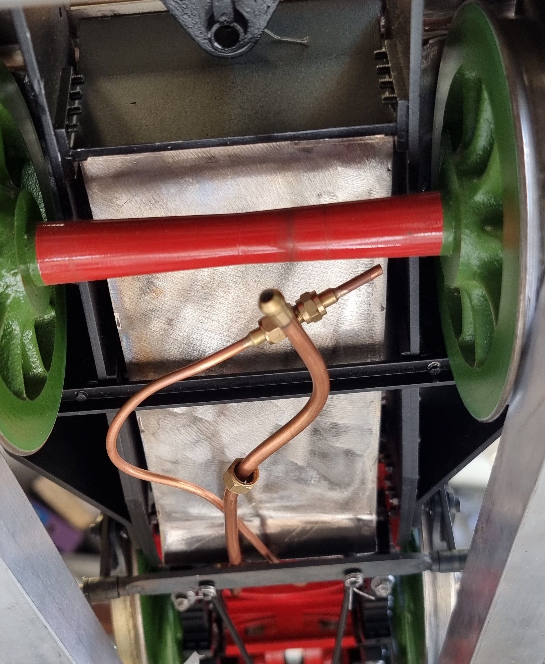
From underneath
Lastly a quarter view...
I still look at this and ask, how did that fit? When I say no wriggle room I'm not kidding, not only is the pan a close fit between the frames but you may recall that I only have about 1mm clearance on either side of the firebox from the running board supports? I'm amazed.. well done John, your drawing was spot on, that's another pint that I owe you...:)
I will leave the ashpan at this stage for now, when I get to the final fitting of the boiler I'll then take care of the rocking grate and damper lever. I will also need to make up a frame to fit in the pan for the grate to sit on and for the dropping grate mech. The current plan is for the grate to be made in 5 pieces + the drop grate to be able to slide in through the Firehole door.