

The outside motion brackets are tricky little buggers, first the castings are not identical, they have many surfaces to keep an eye on for size and also on deciding what to use for a datum?
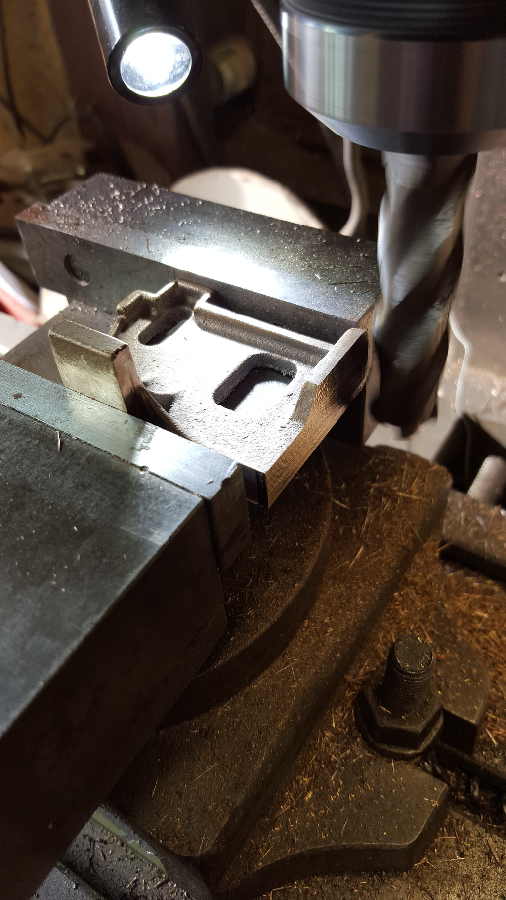
As these are important for the motion I decided to first tidy up what I'll call the slide bar slipper edges as these need accurate placement on the frames, the rest is not so important other then the distance from the frame to the valance and it's height. Here I find what I believe is an error on the drawing as Don has the distance from frame to outside edge of the bracket as 2 9/32 and yet the same distance for the expansion link bracket is shown as 2.250? Now the valance on 4472 runs parallel with the frames, the running board does widen a little near the firebox but not the valance itself. So, I have made the outside motion brackets to 2.250 to match the expansion bracket. As I said on looking at the castings and assessing which is most important I decided that the slipper placement was of most importance and it happens that this is the biggest error on my castings, one being further out than the other? I needed to ensure that I had 1 1/32 between the frames and the inner edge of the slipper which was what I did first, well i say 'first', it was the first to finished size with other surfaces being machined square first to keep things...well square:)
First picture shows the mounting face being machined to size, while in this position I also squared off the back edge of the slipper...
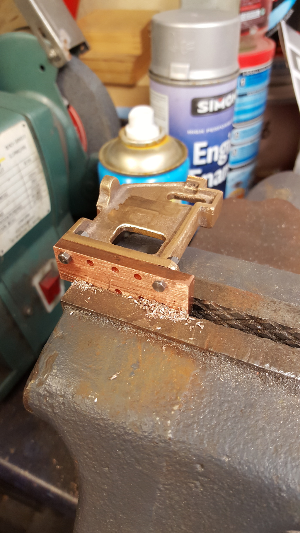
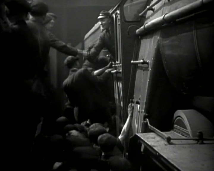
Not much to add about the other surfaces...some were machined and others filed.... to drill the mounting holes to accept the 7 BA bolts i made up a drilling jig, this was from 5/8th copper ( the only material in stock 5/8th wide which matches the width of the mounting plate. I marked and drilled the first two holes on the mill, bolted the plate to the back of the frames and transferred the hole centre's ready for drilling back on the mill. Next I marked one of the top holes onto the bracket, lined up the jig on this and held it in the vice as seen in the picture ensuring that all was parallel, of course, and drilled the holes, two first for securing with 7 BA bolts and then the rest to finish.
Here's one of the brackets fitted temporarily to the frames, the machined front face was just to remove the casting ID number. I won't paint these yet as they aren't finished, the slide bar slipper depth has been left oversize. I won't machine these until the outside cylinders have been built along with their slidebar's, I can then machine to fit avoiding the possibility of needing shims as Don suggests.
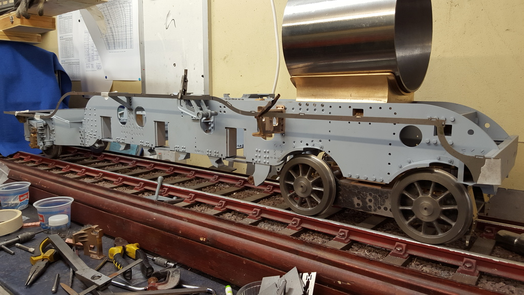
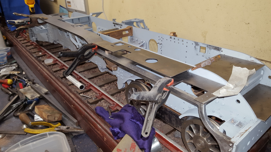
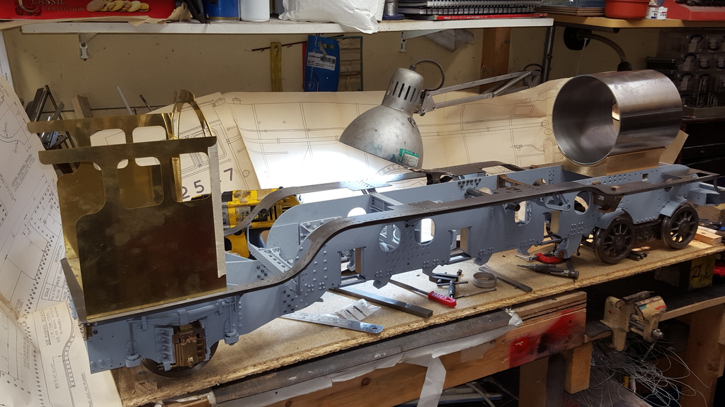
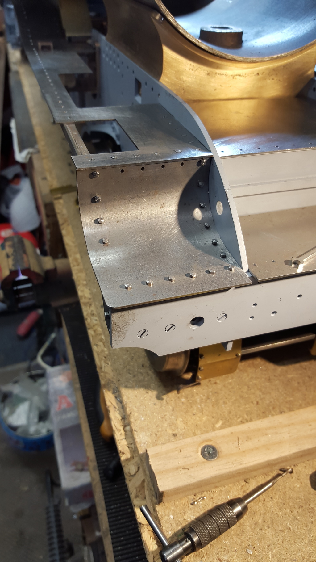
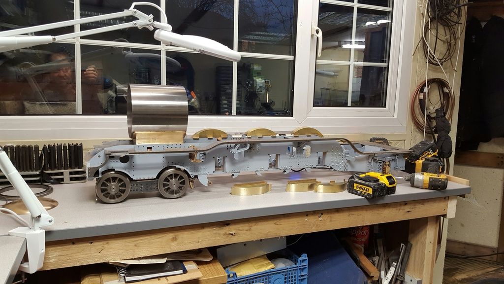
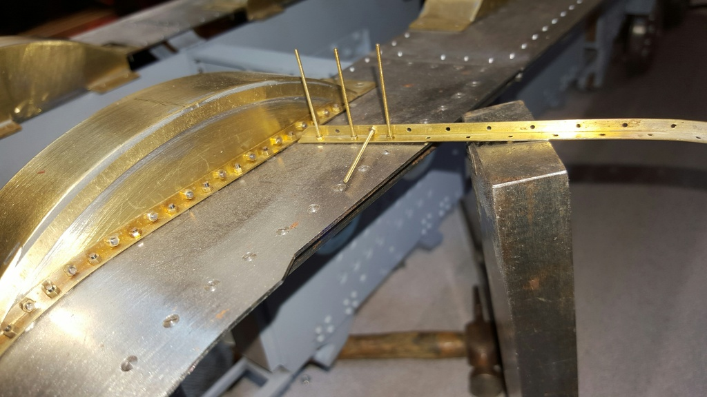
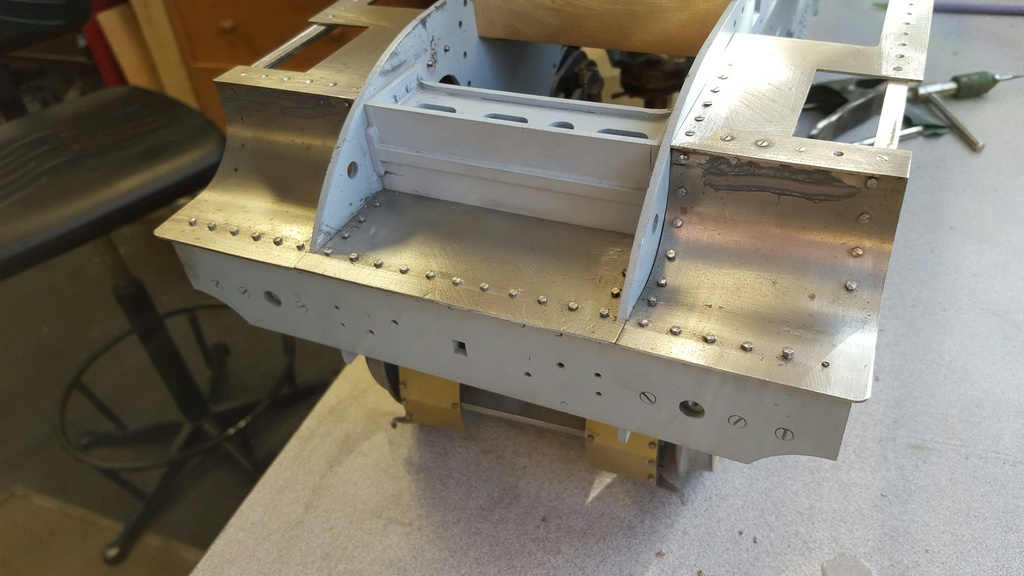
I wanted to see how things were progressing and that all of the running board supports were where they needed to be for a straight valance, the best way to do this was to align one of the laser cut valances along the various mounting points to see how it looked...i think the picture speaks for itself....
I decided to do a little work on the valances next to get an idea of where/how the various running boards will sit and also to take note of what may be the best order of doing things.
First picture shows the laser cut parts assembled, I did the curved top sections by hand using whatever radius bar was nearby to help shape the parts to match the valance profiles.
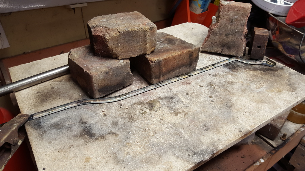
Next was to solder all the parts together, I was in two minds here whether to use soft or silver solder, silver being the best option for it's strength and soft being the safe option in that these are very long ( nearly 4 foot) delicate parts that could well twist/buckle if not very careful with the heat. I bit the bullet and went for silver solder, Picture shows that I had to do this in a number of steps due to the valances being far longer than my heating hearth which made things even more tricky. As can be seen the valance is held either end by a clip/weights and bricks were laid at intervals along the length to hold everything in place, all joints were given a good coating of flux and 0.75mm 55 flow was cut in strips and laid spaced out along the length. I wanted to be able to see the solder flow and also have easy access to the job so I first set the heating board up high on the hearth and I also heated the job from what really is the wrong side, that is heat to the side with the solder on. However by being careful in heating, starting first from one end at the back just to get things going it was a straight forward exercise to heat the job without to much heat directly on the solder as i moved along..hope that makes sense...the flame was close to the solder but not directly on it while I chased the heated flux along. To be extra safe I didn't allow the steel to heat too much where it was hanging over the edge of the board, each section was left to cool and then the job was moved along the board to the next section.
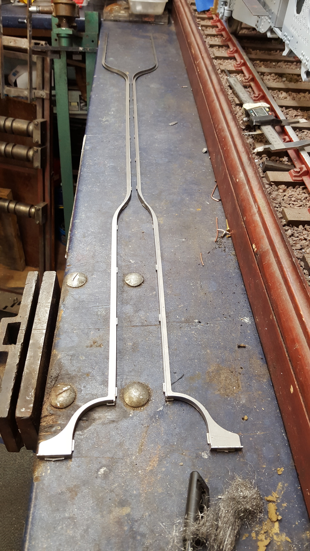
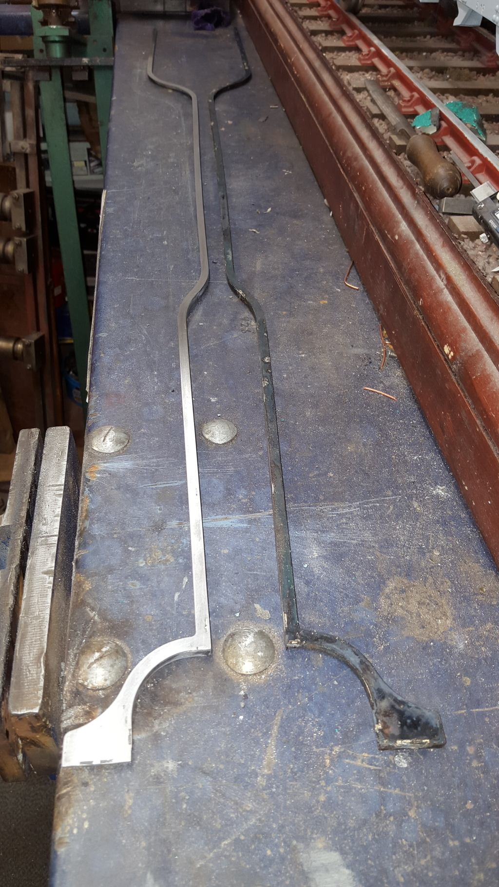
Final picture of the valance fabrication to show one valance filed and cleaned up and the other ready for the same heat treatment, sorry for the quality of the picture, trying to fit in something this long isn't easy and not very close.
To complete, the valance needed curving so that it sits under the cab floor and attaches level to the top of the drag beam and the mounting holes need drilling for the IIRC 17 8 BA bolts to attach the valance in 7 areas, front buffer beam, outside motion bracket, expansion bracket, main running board support, boiler stay outrigger, rear trailing frame stay and the aforementioned bolts to the drag beam, so plenty of holes to get in the right place
Continuing with the valance's I had now done one side except for the outrigger which was be fitted once I had marked and drilled the 1/16" holes to attach it to the boiler stay. I took my time in getting the valance to look right as IMHO it's such an important part for achieving the beautiful lines of a Gresley pacific. I have drilled and tapped all of the 8 BA mounting points that hold the valance to the front buffer beam, outside motion bracket, expansion link bracket, central running board bracket, trailing frame bracket and the rear drag beam leaving only the outriggers to do. The drawing has the outriggers mounted to the valance via it's sides but photo's show the outrigger mounting plate is under the running board and so I will follow suit, it's difficult to explain this now so will leave it until when the outriggers are fitted.
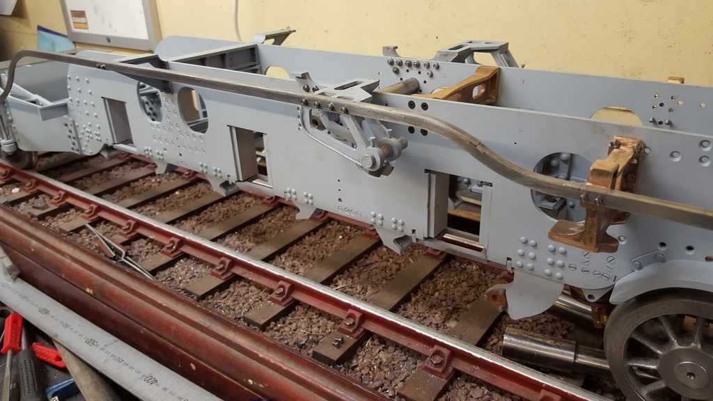
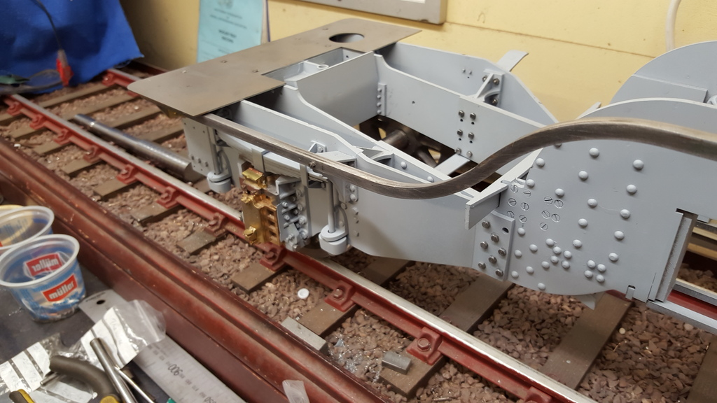
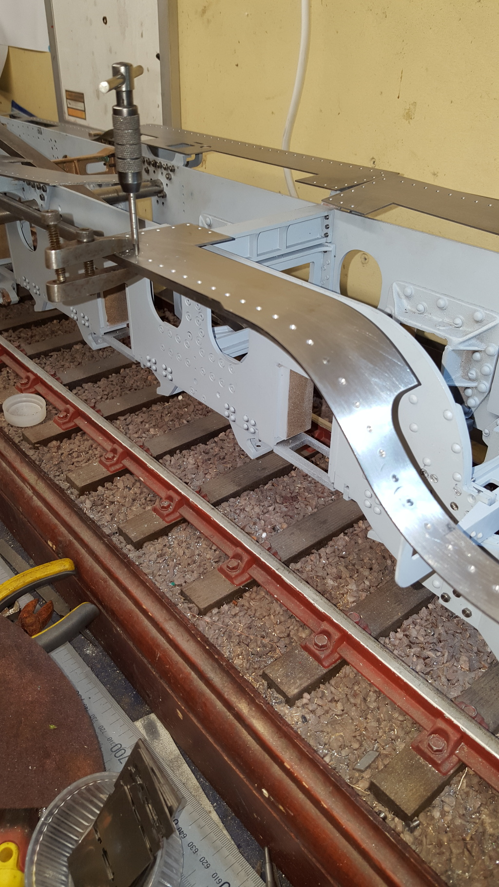
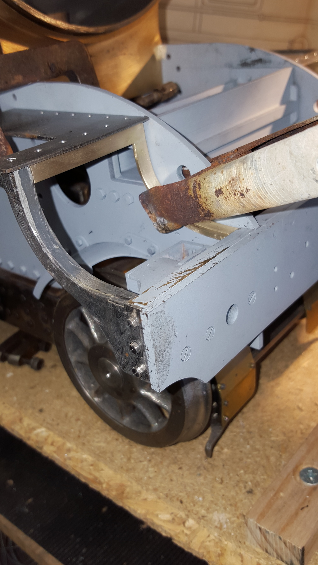
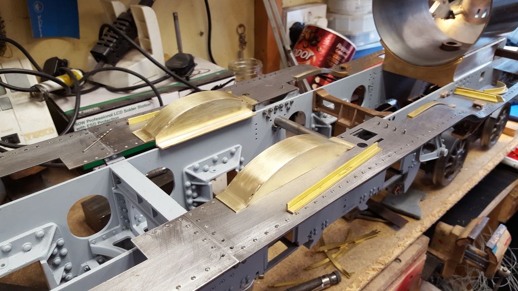
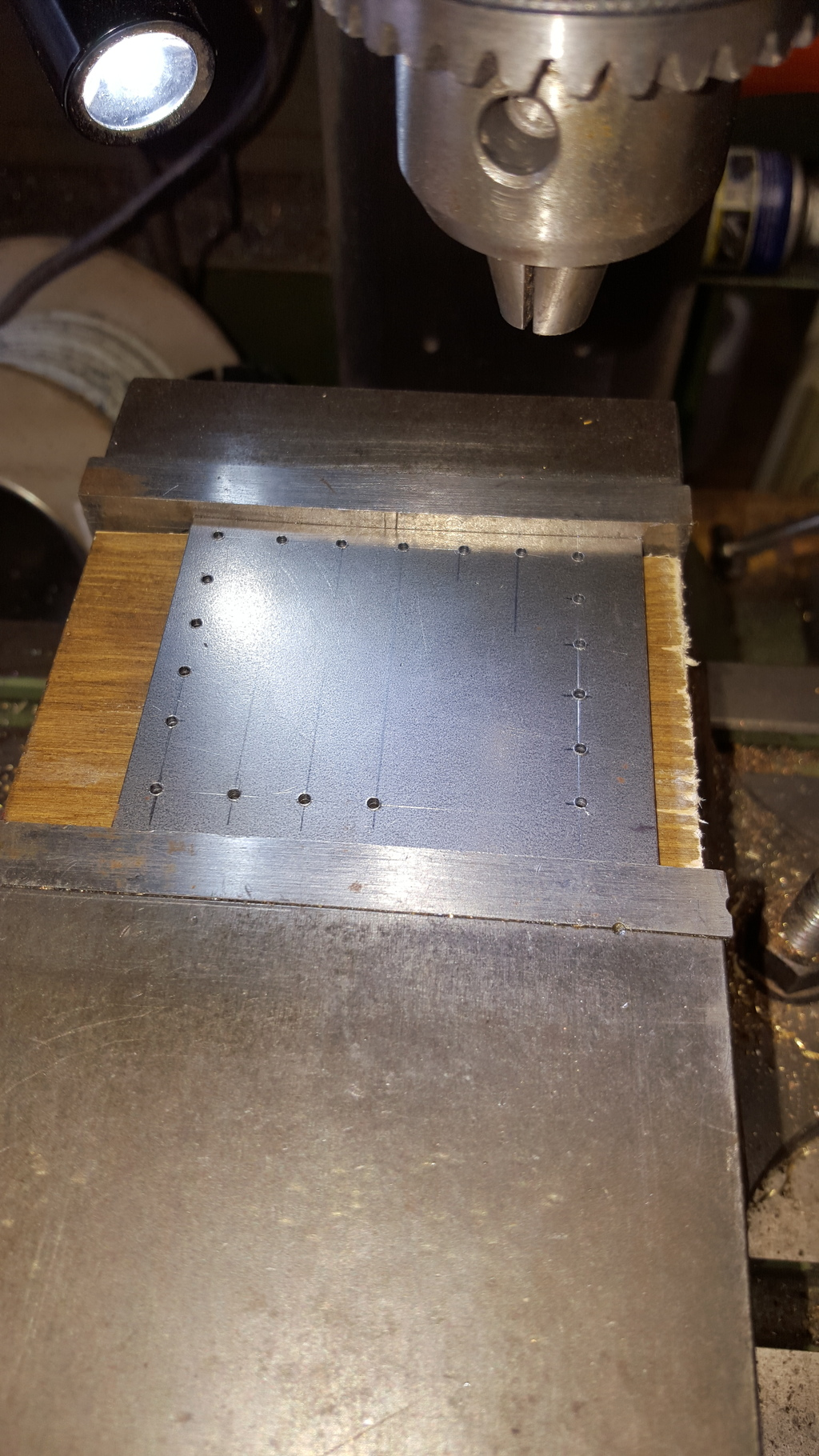
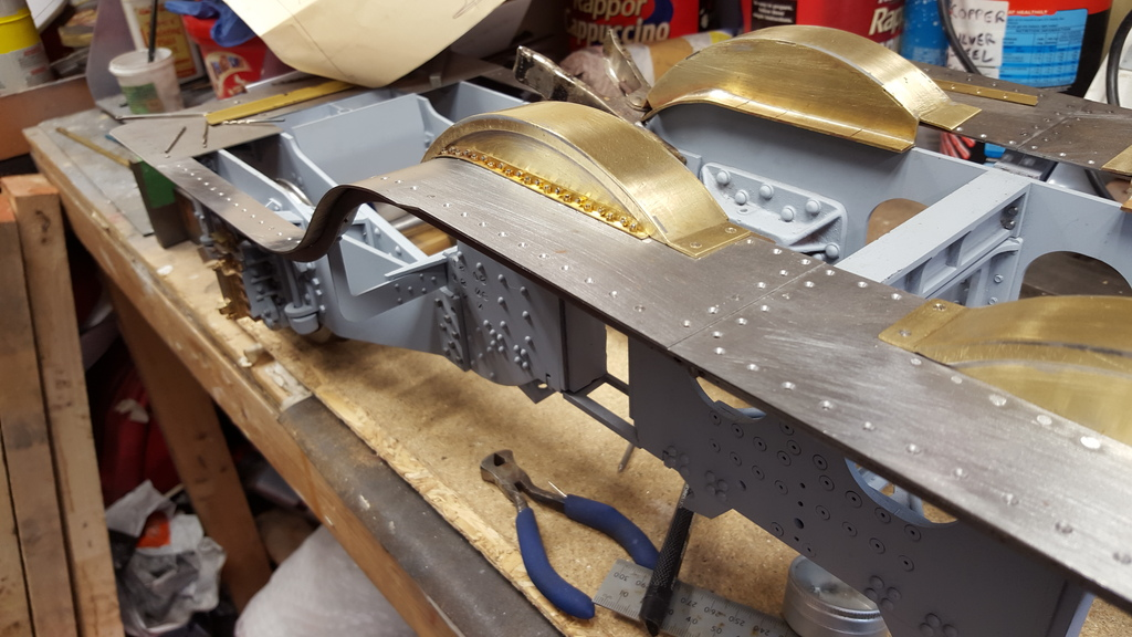
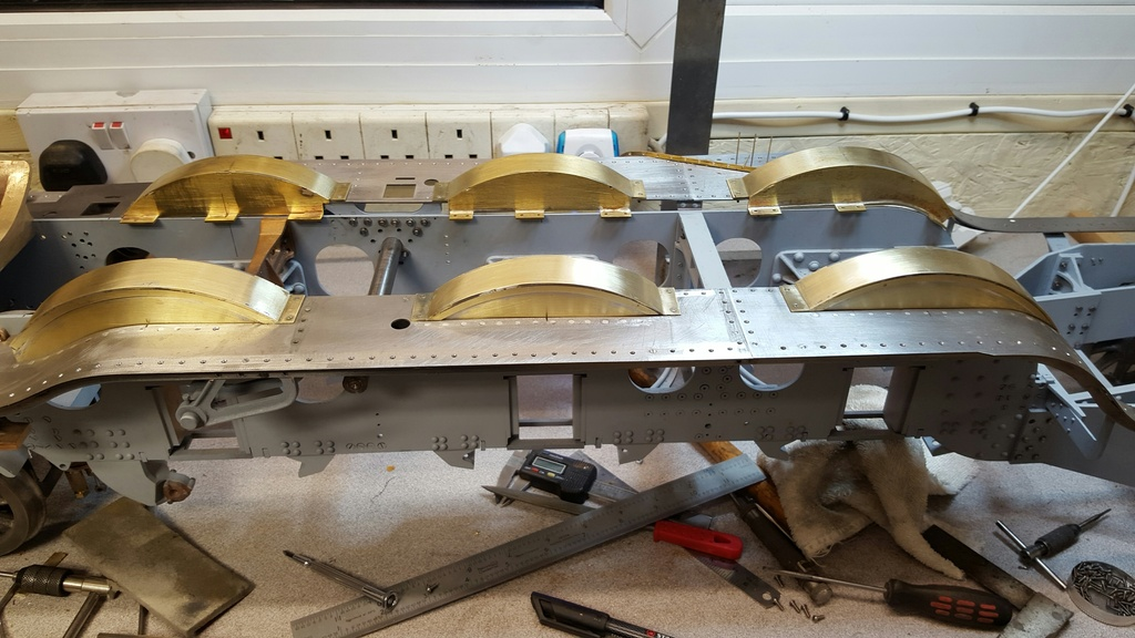
As the valances are so long I've taken a number of photo's to show how things are progressing..I'll start at the front end....3 hex bolts to the buffer beam and two to the outside motion bracket. Also of interest is the two central running boards dry fitted.
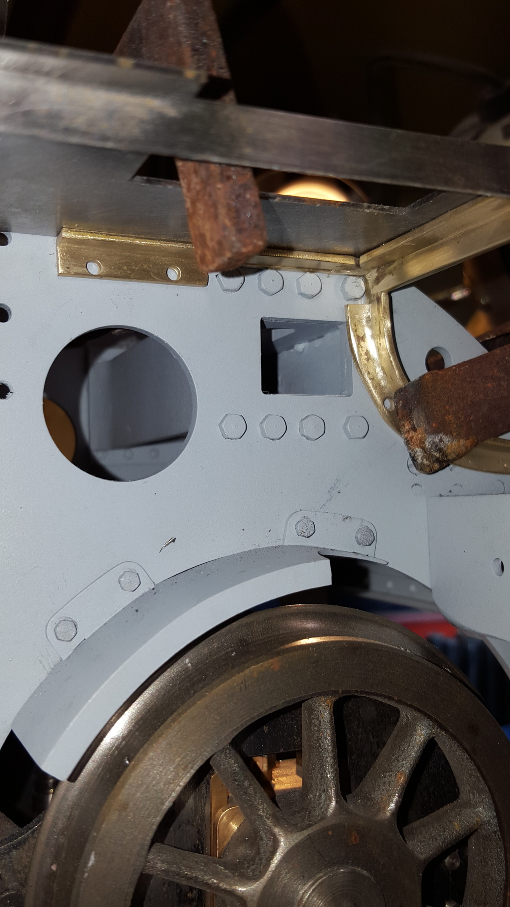
Moving along we come to the mounting points on the expansion link and the central running board bracket's, a couple of things to note here, first the error that I mentioned earlier with the bracket heights mis-matching, not sure what the thinking was behind this but the two types of expansion link bracket shown on the drawing ( early type and later modified A4 type) have different heights above the frames which then effects the running board height? The early type as I'm doing shows 5/16" above the frames whereas the later type is 1/4", to confuse matters more the central bracket is also drawn as 1/4"? ok it's only 1/16" difference which is unlikely to be seen but the question is which is correct? on looking at the valance, in particular it's curves the lower 1/4" height doesn't flow like the 5/16" does so this is what I'm going to do, which is good as although changing the central bracket height is easy doing the same to the expansion link bracket would involve remaking the bracket. The other point of interest is the central bracket, as drawn this has no place for the two mounting bolts to attach too, so I made up a small plate that is held under the bracket by two csk 8 BA screws through the top of the bracket thus giving me a flat face to drill and tap to secure the valance.
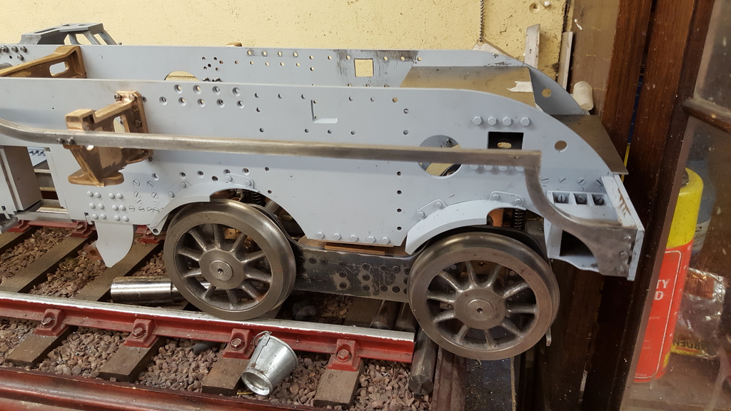
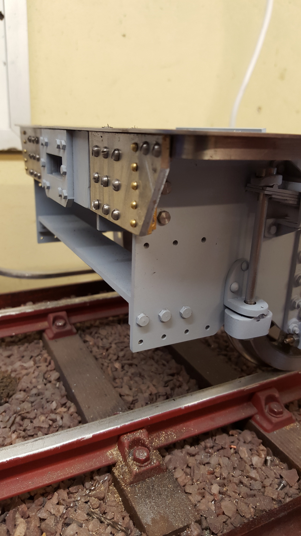
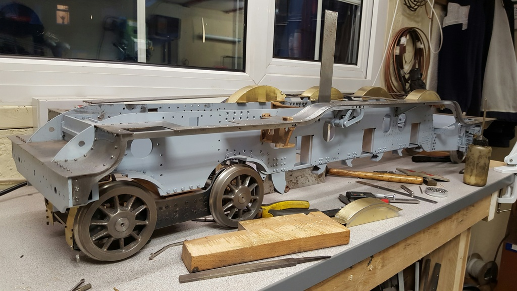
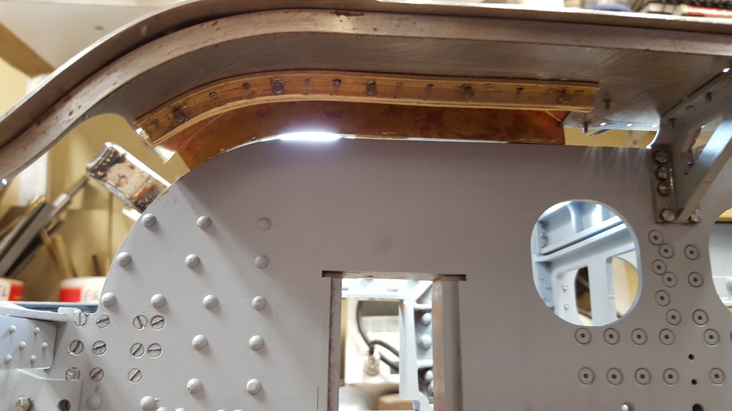
And here we have the rear section, the outriggers when fitted will sit in the 'S' bend , you can see the boiler stay that the rigger mount's too sticking out from the frames where they drop down for the firebox, during construction I kept a close eye on the valance position to ensure that it was matching up to where the rivets sit along the running boards, in the picture the valance disappears under the cab floor and this needs to align so that the rivets/screws that run along the cab floor are central to the top of the valance plate.
Lastly for the valance fixing, this picture to show how the valance curves around the back of the cab floor and is secured behind the drag beam.
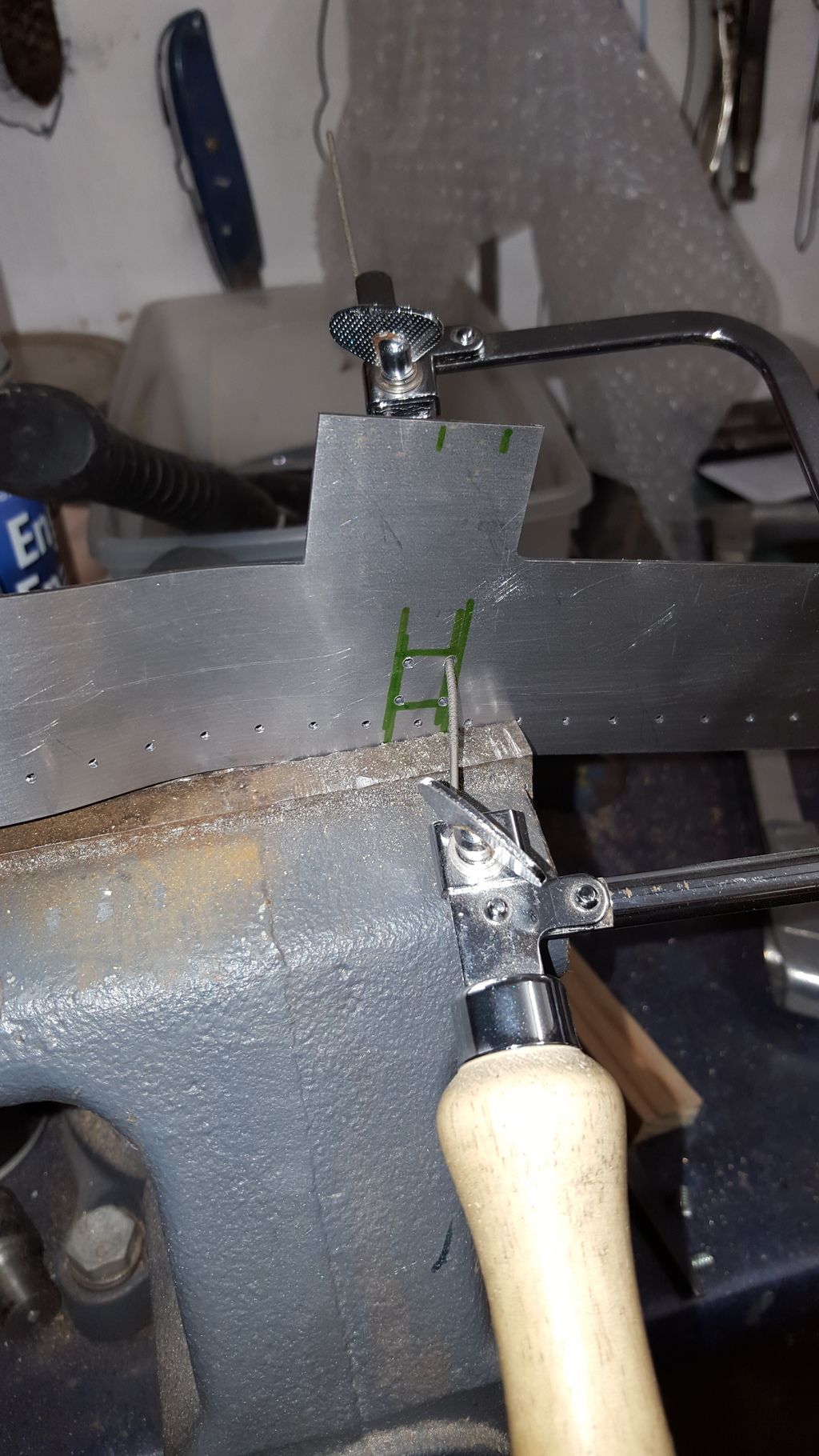
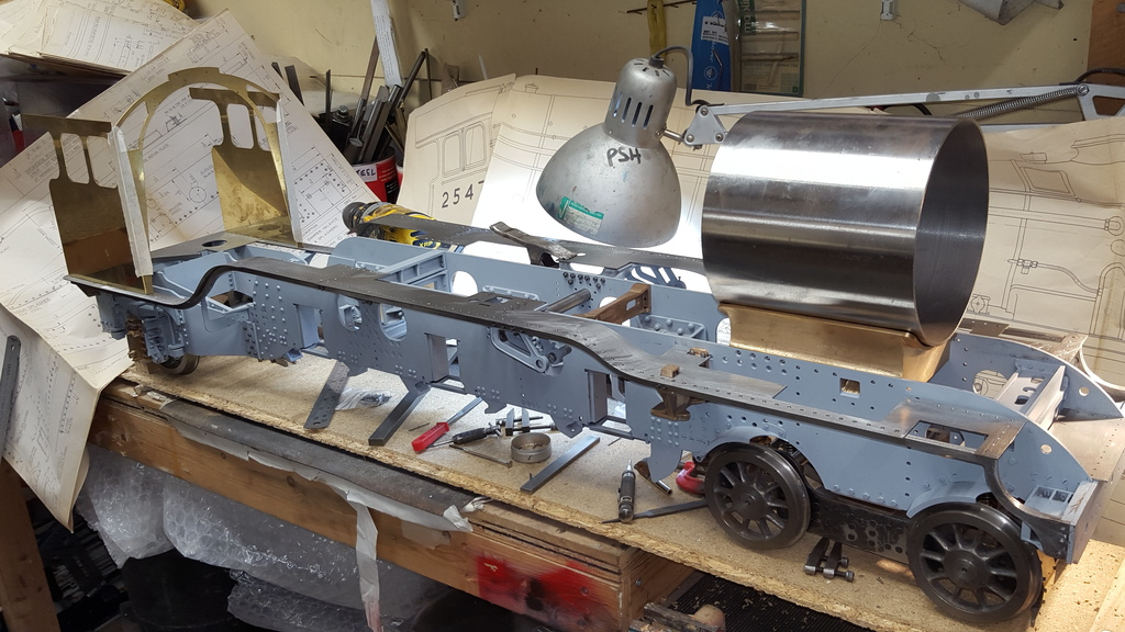
Before I moved on to fit the valance to the other side I wanted to be sure that all was going to plan and the best way of doing that was to test fit the front running board and the long valve travel cover above (upper running board). As with the rear section I needed to first drill copious amounts of 1/16" holes before bending the board to follow the shape of the valance, I discovered something here but more about that later.
I then needed to cut out a small rectangle that is a 'cut to fit' job so not cut with the laser, this is to allow a step that is part of the outside motion bracket which the upper running board sits on. I had to machine a little off the top surface of the motion bracket to allow the running board to sit flat, at first this confused me until I realised that I had stipulated 1.2mm material for the valance/running board sections as this looks more to scale. This meant that the top right angled sections of the valance were thinner than what Don had drawn using 1/4 x 1/4 x 1/16 material...no big deal all sorted now. Picture to show the cut out first being removed using a jewelers saw and then finished by hand filing, I also needed to remove a small amount from the back edge to clear the motion bracket mounting flange.
Once the bracket was back in position I laid out the running board sections and the long valve travel cover to see how things were going, happy to report all is good. The rivet holes are running down the valance nicely so I know that these parts will all go together as they should, front edge of the running board matches the inner section for overhang so the extra length of the boards to allow for the curves is spot on...a big thank you here to John Baguley for it was his help and knowledge of 3D CAD that made this happen to a very accurate fit. The valve cover is also spot on as when being set back from the front at the correct distance and held at the correct height it's rear end that blends into the downward slope of the running board fits perfectly.
Now I mentioned at the beginning the 1/16" holes for rivets, I had assumed that the boards were held to the valance via a mixture of rivets and round head screws for where parts needed to be removable and so ordered a few hundred 1/16" rivets in preparation. As per usual before starting something new I spent an hour or two looking through my reference photo's to check that the small details are right and here I discovered that 4472 has slot screw heads along her boards, not rivets? I was a little surprised as my over Pacific, LBSC's Heilan Lassie ( I have built her as 4470 Great Northern) does as to the drawings, ok it's a toy in comparison to Don's work but i had assume they would both be the same, good job I checked first. So, after spending more time researching I could see from looking at my reference collection photo's that it was clear to me that the boards are held with slotted csk screws. I have a number of images for 4472 from NRM with rows of open holes in view which suggests that the panels are all removable, I have one slightly blurred very close image where some of the screws have been removed, left lying nearby with others still in place which shows slots in them. I hate slotted screws on models because it looks unreal but if that is what's fitted then so be it.
Here's a couple fo the photos that helped me make the decision, I decided to use 10 BA csk screws which look the right to me, or course, this meant a lot of drilling/tapping/counter sinking of 1.4mm holes, literally hundreds of them.
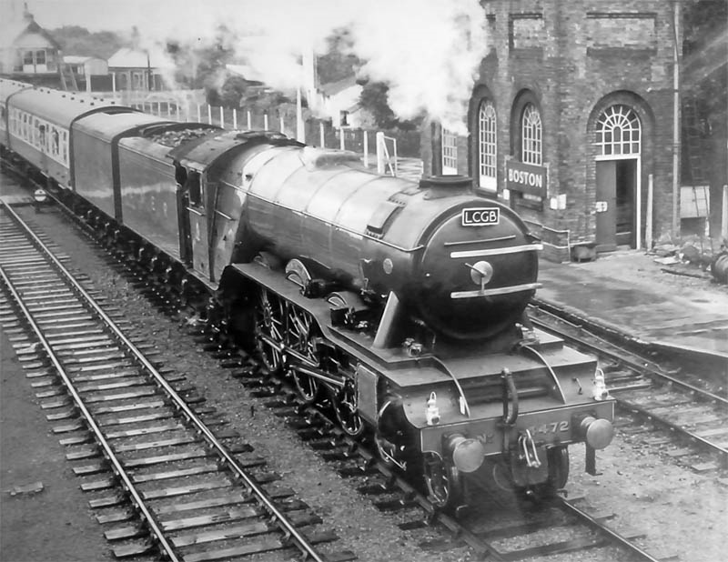
First a good picture of 4472 after preservation which has been taken at just the right angle to show off the smooth lines of her running boards..
Here's a close up of the centre splasher where if you look closely at where the two boards meet you can see some of the slotted csk just showing, ignore the various bolts sitting on top as they are from somewhere else, of note is even this close it's still very difficult to see the screws that secure the boards.
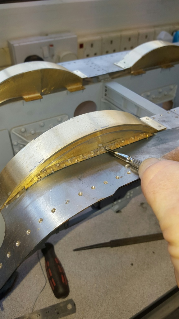
Both valances have now been fitted, all running boards have been drilled, csk and rolled to match the valance. Picture shows a start being made on securing the rear running board. I secured the cab floor first and then worked my way to the front. I checked the position of the running board where it fixes to the expansion link bracket, checked that the drilled holes ran down the centre of the valance angle, noted the amount of overhang at this point and selected a suitably sized piece of BMS to use as a spacer to ensure the boards run true along the length of the valance, in fact I have two spacers as the rear section seen in the picture widens just before it curves down to match the width of the cab floor.
Once all of the screws had been fitted it will be an easy job to remove the entire valance/running board as a unit, requiring the removal of around 15 screws, this will include the splashers. A short word on these, the splasher cut outs all line up nicely being centred on the axles, I'll make a start on describing these soon
After two days of drilling, counter sinking and tapping around 200 10 BA holes I thought I'd have a play and put some of the cab components in place like you do...she's finally starting to look like a Gresley pacific. A couple of pictures just to show how she's looking...
view from the rear
view from the front
NB: My thoughts at the time:
I have a lot more work to do on the boards and think that I will continue along this path and get the bulk of this fairly large part of the build out of the way now. Main jobs are to fabricate the numerous support brackets for fixing the running boards to the frames themselves, some of this involves rolling right angle to match the valance which should keep me busy for a while. It would be a good idea at this time to remove the 2-1 lever stay for detailing and I may as well turn up the required bronze bearings at the same time. I need to roll the two outer front running boards drill and tap to fit, need to make up the support frames for these first. I will also tackle the long valve covers and might as well do the splashers while at it. I may as well do the cylinder mounting plates as I need to remove the bogie bolster so best get it done while the front is apart.
I am very, very tempted to do the cab after that lot, just for something different, there's a lot to do here but to help I have some very detailed close up photo's which will help greatly. It would be nice to do some plate-work as a change from machining of which I have much more left to still...all good fun though...
:
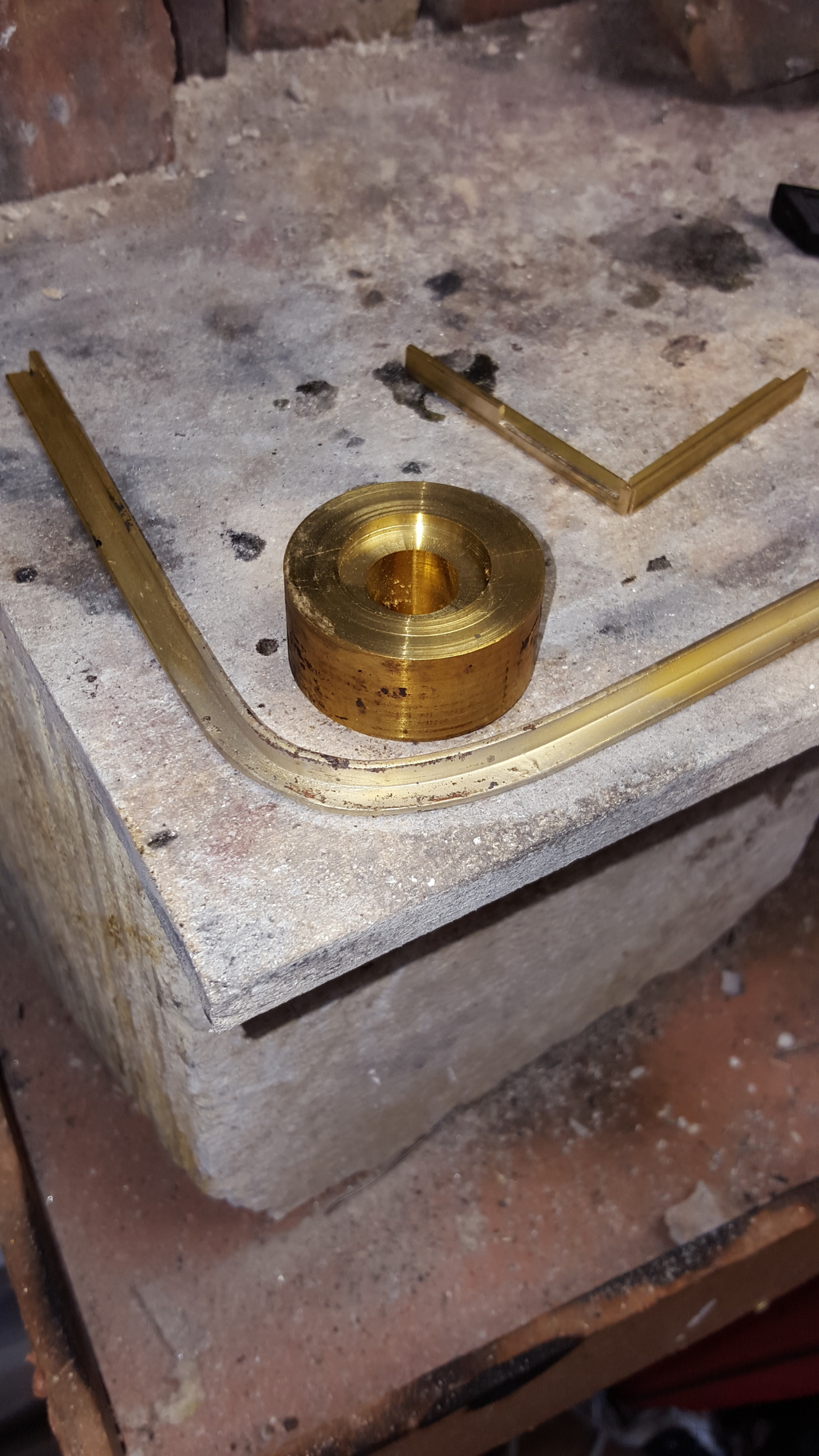
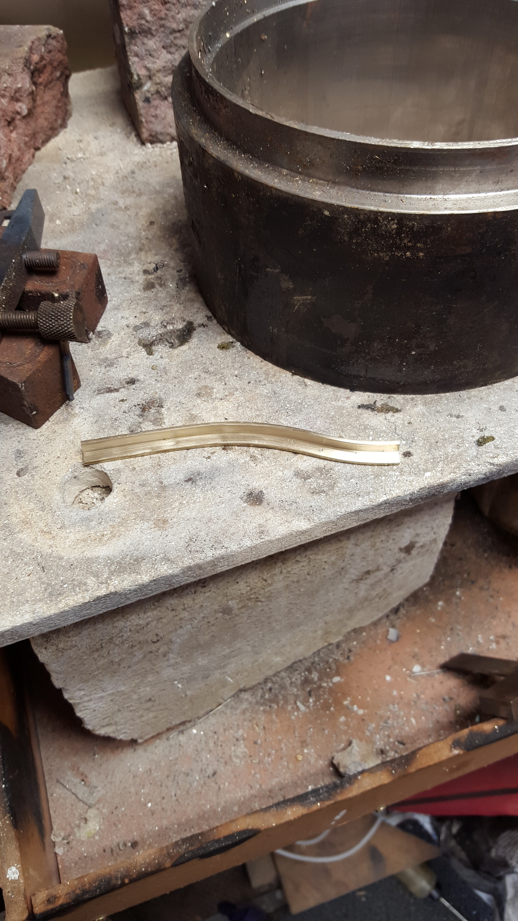
I have a few more photo's than usual to show here as it may help others to see how I did this part, the part in question being the front support for the curved section of the forward running board, all parts are made from 1/4 x 1/4 x 1/16 brass angle. First I tackled the curved section that needed to match the curve of the valance, I selected an off cut of brass bar that was slightly smaller in radius than required and fixed it to some thermalite board, took a 12" length of angle, heated it up in the middle being careful not to heat it too far and holding either end bent it around the bar, wearing welding gloves ...naturally...
I did this process a couple of times checking it against the outer valance on the model, once happy with the shape I cut off the ends allowing for the other two parts to fit correctly. Picture shows the part at it's required curve, the other two parts can also be seen ready for silver soldering.
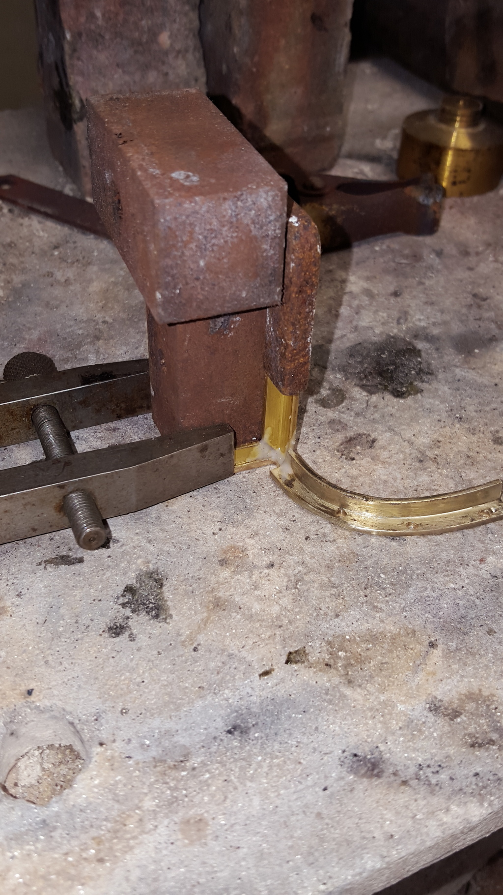
Using some rusty blocks I clamped the sections in place for two of the axis with the third curved part lying flat on the board, mixed up a semi thick flux paste and silver soldered the parts together ensuring that the curved section was at the correct angle. I drilled the mounting holes for securing to the frames first, the 10 BA tapped holes for the boards will be done in situ.
The finished 3 axis part ready for fitting, the slot cut in the rear part is to clear the 4 6 BA bolts that hold the 2-1 lever stay to the frames.
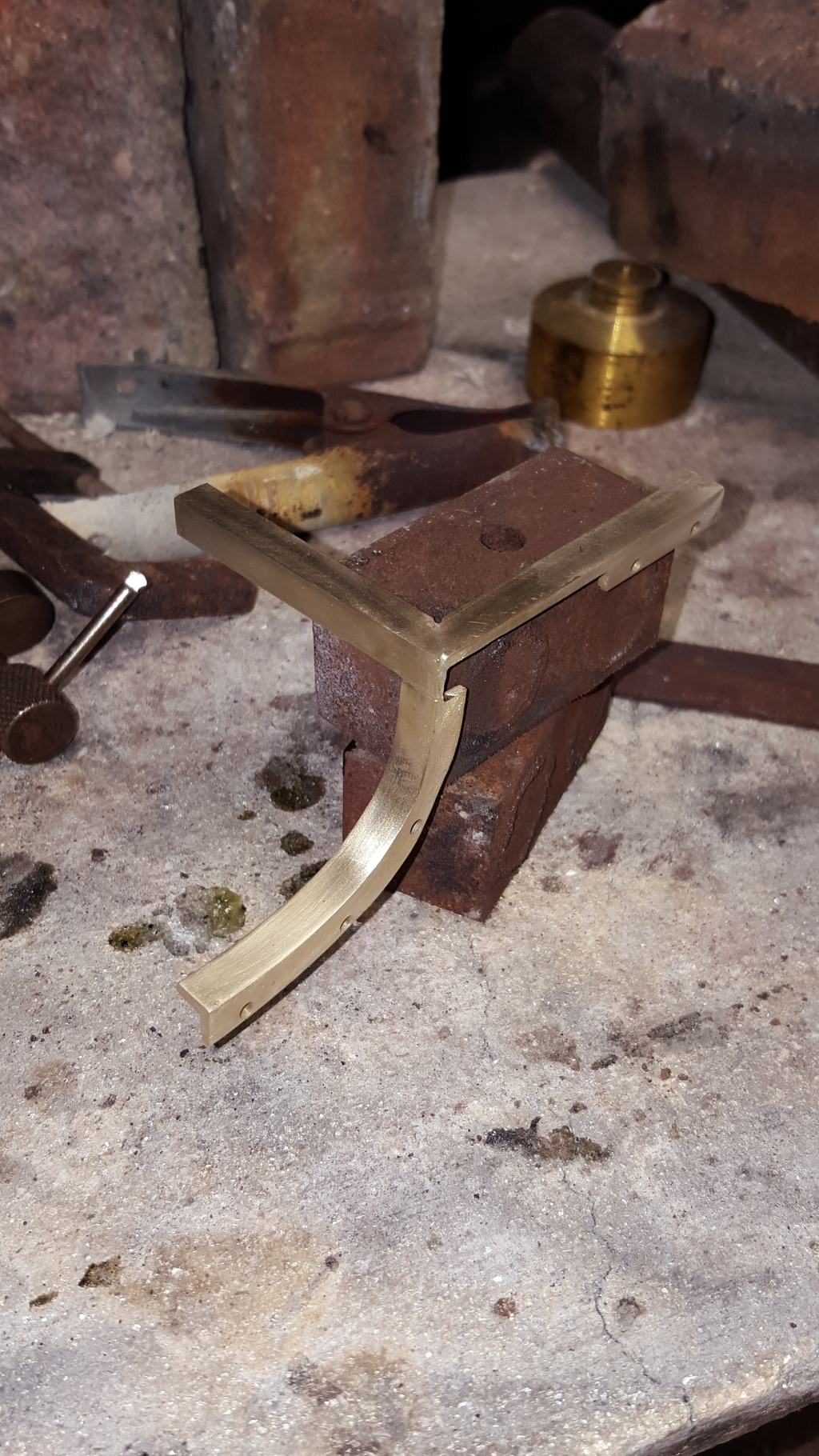
I haven't bolted the part in place here yet as I'll need to remove the valance/boards first to drill the holes but I will show how the part fits as an aid for anyone else at a similar stage on their own builds, mind you I'm sure that this can be done a number of different ways, this is just my chosen method..
view from the front
And from the rear below the running board, you can see how it fits around the 6BA bolts mentioned, once fitted I'll file the outer edge were it overhangs the opening for clearance of the 2-1 lever. I deliberately drilled the mounting holes off centre to give more room for access with a box spanner as it's going to get a little tight under here..
Splashers and their supports....
I then made a start on the splashers (I do a lot of jumping from one part to another), first I made the supports for the leading and driving wheel splashers, the trailing splasher I still needed to do a little more R&D to work out the correct size of the angle support. Theres a bracket that runs along the outside of the splasher above the running board rather than just underneath like the other two, I suspect this to be a smaller size 'L' section than the others (NB: it is). The driving wheel support is straight forward being a straight piece of right angle but the leading and trailing supports curve to match the valance. The leading support drops down following the forward curve and then curves back to follow the lower board...first picture shows a leading support after forming, I used the off cut from the smokebox to help form the shape after heating as it was very close to the radius needed.
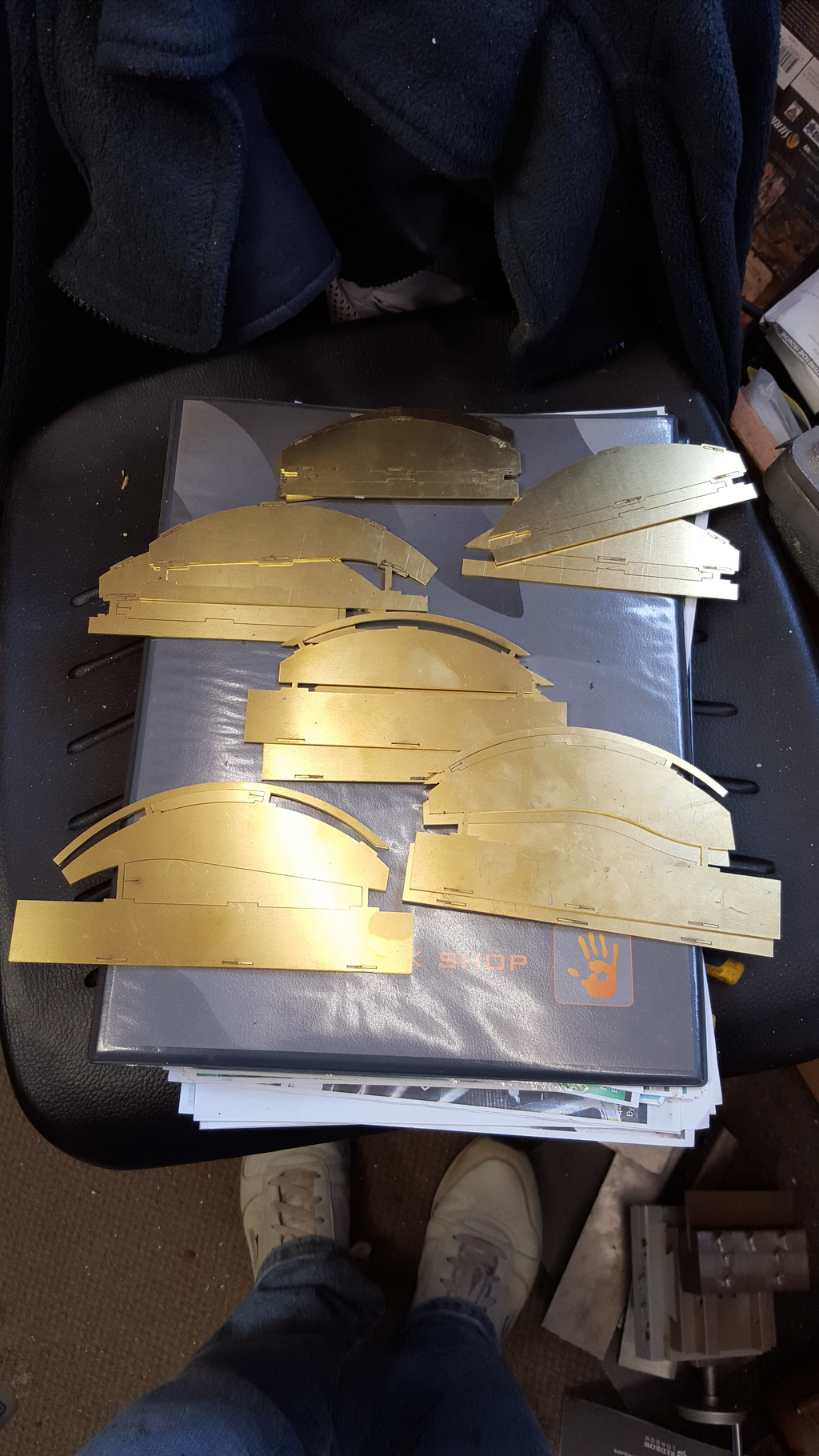
Thought I'd remind everyone of the laser cut parts that I have for the splashers, kindly drawn up by John and cut by Malcolm so we can see the parts involved...
I haven't taken photo's during the soldering stage as it's much the same as before, being slot and tab construction it's pretty straight forward..in this picture we have the driving wheel splasher sitting in situ, I still need to solder on the raised trim arc to the front of the splasher here, this will be attached using soft solder. The picture also shows the support brackets for the front and driver axles ready for fitting, as mentioned these will sit under the running boards. Note the right-angle support on the rear of the opposite splasher, on the prototype this is broken up into a number of small right angle brackets rather than one long one, I'll do likewise a bit later once I've decided on exactly how much detail I'm going to put here...the prototype has a number of pipes and also oil boxes that seem to feed various parts here. Lubrication is something that I'll need to give some thought too soon, in Don's design he has hydrostatic for the cylinders and mechanical for the main axles/motion etc. 4472 lost her hydrostatic lubrication very early in her career, in fact she was never meant to have it and was recalled to have wakefield mechanical lubricators fitted, I believe 4470 Great Northern had the same arrangement from new. The early A1 batches varied with either hydrostatic or mechanical lubrication until it was decided to go with the mechanical type and all were so converted.
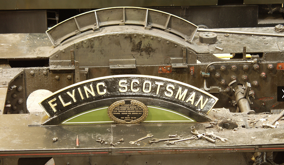
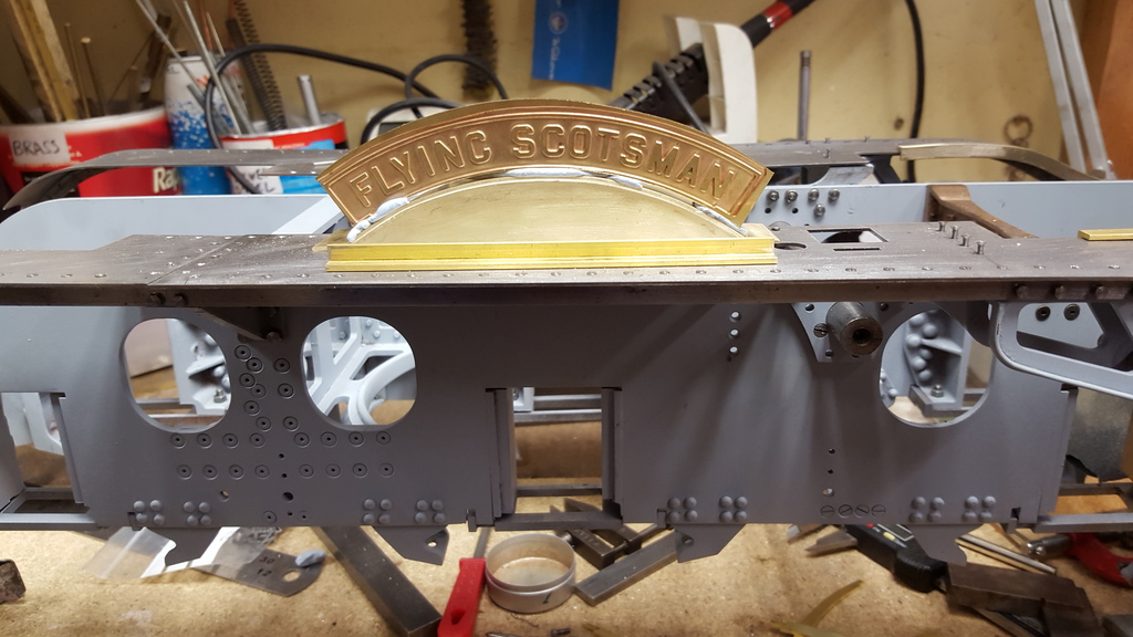
Last picture...well I couldn't resist.....the lady has a name....I got these from Diane Carney a good few years ago now, good job too now that she's no longer doing brass etching (NB: I believe that she is now back), I have a complete set including name board, the unfinished tender plates can be seen in earlier photo's...I haven't ground the plate down to size yet, the bottom doesn't have a brass lip as seen here and the other 3 edges need a cutting down. I have some good reference photo's for the nameplate bracket which I'll make up later....
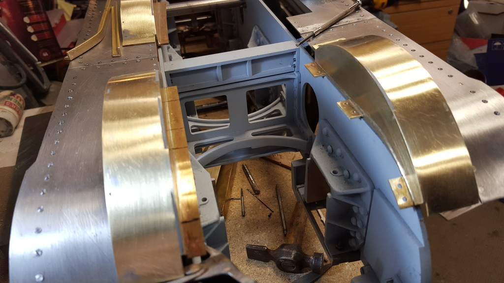
All six splashers have now been fabricated, the bulk with silver solder with the front trims attached with soft solder. I still have a lot of work to do here to complete this stage, more than I imagined as the closeness of the parts makes drilling impossible without taking everything apart first. The trailing splasher is further advanced than the others as hopefully can be seen in the picture, the front lip has been trimmed to size, drilled and csk to accept the two 10 BA screws that secure it to the running board, the rear lower edge of the face trim has been cut to fit the curve of the running board as it slopes back , the back supports have been cut and drilled to accept for 8 BA bolts and the main support that runs under the board has been riveted in place using 1/16 alloy csk rivets and bolted to the splasher with 8 BA bolts. the following pictures will show this a little better..
This picture shows the rear brackets ready for fitting to their respective supports, note that i have already marked the other side reading for cutting. I need to take everything apart again to fit the right angled supports and so will probably do all of the supports together once all the other parts involved have been done. The top inner corner of the rear splasher needs to be cut back at an angle to allow clearance of the boiler and its cleading, since this is a very close fit with next to no gap I'll leave this until the boiler has been placed on the frames and checked for clearance. The driver and leading splashers aren't as close to the boiler and thus do not need cutting back.
Here we see the front of the splasher, the alloy rivets running along its front face have been filed flush and any dips/marks will be filled before painting, I have gone over the csk holes to make them a little deeper so that the mounting screws sit as flush to the running boards as possible

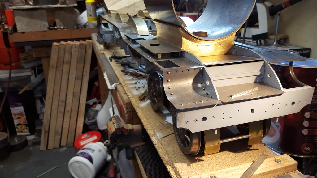
Now you may recall that I was going to do a little more R&D to find out if the bracket that runs along the outside edge of the rear splasher as fitted to 4472 today was there during the 30's, as there's no mention of it on Don's drawings. I re watched the film 'Flying Scotsman' 1929 to see if I could answer this question and right at the end I was rewarded with this still that will do nicely...
Going back to the running boards I have now finished roughing out the drivers side and once I can get a hand to turn the loco around will get the other side up to the same stage, jobs done today are the front curved section of the board and the extra detail mentioned before on the trailing wheel splasher. First the curved front section, having marked out the holes I held the two sections mirrored together in the machine vice and drilled the 1.8 mm holes following the same theme using 10 BA bolts to secure the section to the frame/valance. After that I bolted the two together and profiled the outer corner to the 1/8th rad as per drawing.
Next picture shows the drivers side section fitted, now I made an error here, I had made a note to add an extra row of holes to the top edge as I had seen this in some photo's, or I thought I had, but it's now clear to me that 4472 didn't have any bolts along the top edge except for the two outer as seen fitted here, so these will need csk/filling, perhaps I had seen them on another pacific? Now from what I can tell the front row of bolts along the top of the buffer beam today are countersunk but I'm not so sure if they were before, I have a good closeup from the 20's which shows hex heads elsewhere on the front which are csk today. I decided to leave them as hex heads. I have also left the holes for the lamp irons and grab rails until they are fabricated, finally the curve was created in the rollers and then flattening out the front edge as it's flat.
Here we have the long valve cover in place to check for position, I needed to shorten it a little along the rear edge as it was a little long, later I'll fabricate the upright sections but for now it's just sitting on some steel stock so I can check all is as should be.
Lastly the extra right angle along the splasher/running board joint, I have used 12 BA bolts but may change these to 14 BA as they look a little large to me, the bolts are fitted as dummies with the drilled holes countersunk from undernearth and filed down. The right angle for heated to allow it to bend to the profile of the running board, at present it's just sitting in position while I decide what to do about the bolt size, they may not look so big with a coat of paint on them, we shall see.
NB: I did change these for smaller.
At this stage I had a few things to sort before moving on, the running boards needed to have the right angled valance section removed from where they sit on parts such as the expansion link support, main support and motion bracket, once these sections have been removed the running boards will be sitting in their final position and square/flat to the frames, currently they are angled a little due to the height difference. Once this is done I can finish fitting the splashers in their final position. I still need to braze up the support bracket ( parts made) and fit to the frames for the front of the running boards on the side nearest to the camera, other side is done, oh and roll the forward running board to fit.
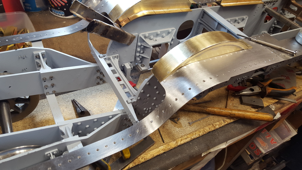
Carrying on from where I left off the picture shows the firemans side ( remember she's an A1 r/h drive) with it's running boards now sitting at their correct height. As noted before I needed to cut part of the valance right angle section away where it met the various supports to get the running boards sitting flat/square. On top of this I also needed to further csk the copious 10 BA screws so that they sit flush as was done previously on the other side. The rear splasher has also been fitted to the boards leaving the middle and front to do. Note that the front curved section of running board along with it's mounting support has also been done, I have filled the holes wrongly drilled (covered in earlier post) with some JB weld .
Ok, so I have now fitted the other two splashers, however before moving on I have taken a small step backwards. Well not really backwards, just that there is a growing list of parts that aren't fully finished yet, most of these I'll take care off when disassembling to paint but I thought it prudent to at least get some bits closer to how I want them. Since I was already working on them this involved the splashers which were far from being finished.
First I concentrated on the firemans side which are now in their correct positions...if you look closely you will notice that the mounting tabs that sit on the running boards have been trimmed and filed down to bring them closer to the prototype, the other side for comparison is still untouched and also need slight adjustment for position. I still need to mount the right angled brackets that hold the inner edge of the splashers to the frames to match the prototype, I've been putting this off as it involves a lot of extra work but I will need to do it soon, the plan is to mark out where to drill the mounting holes and then to do all of them in one hit once the boards/valances have been disassembled. Other than that a little filing down to finish off here and there and I can give then a coat of etching primer. As mentioned before the rear splashers will require more work later in cutting away the top inner corners for clearance around the boiler.
NB: I decided not to fit the right angle brackets to the frames for a number of reasons, they aren't needed for support and in doing so it would take a lot more work to remove the splashers. My current plan is to fit dummy brackets that are bolted to the splasher right-angled supports but not the frames themselves, from above you'd never be able to tell.
Now those who have been following this build for a while will remember the extra bracket that I added to the outside of the rear splasher, having confirmed it's existence in the film 'Flying Scotsman 1929' , I already knew that it was on 4472 today. At the time I wasn't happy with the 12 BA bolts that I used to try and represent the fasteners for said bracket, so I tried some 14 BA screws to see if they looked any better, they do, much closer to the prototype and so that's what i used
Picture shows for comparison the original bracket with 12BA used from the drivers side with the firemans side bracket placed alongside with a few of the 14 BA screws in situ, it looks much better to me and thus I made the change.
Continuing on with the rear splasher exterior brackets ( I just love making extra work for myself). I had to reshape a new section of brass right angle as naturally the holes for the previously used 12 BA screws were too big for the now preferred 14 BA items. I drilled the csk holes, curved the angle and fitted the screws/nuts, soft soldered them in place with the threads then cut down.
Hopefully you'll agree that the smaller sized nuts look much better when compared to the 12's and closer to the prototype.
A picture to show the support bracket under the rear splasher, the others are similar.
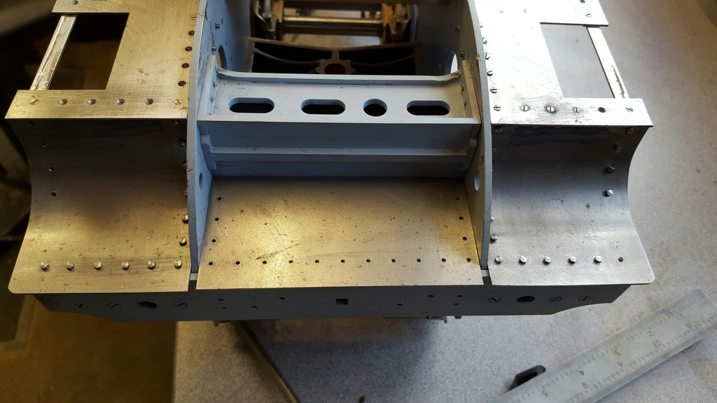
Having done the brackets I was about to move on and take everything apart when I remembered something that had been bugging me, this being the central section of the lower front running board, the section had been correctly laser cut to the drawing but the drawing wasn't correct...the next picture shows clearly what's wrong.....that being the gaps between the three front boards...this is incorrect and worth noting for anyone else building this model.
Now I'm not entirely sure how these boards join on the prototype, they may be how I've done them or more likely they each have a small notch removed from where they meet the frames. Which ever it is I didn't see the need to remake all 3 so just concentrated on the central board and added the missing metal there. I make no secret of how I hate wasting time hacking and filing metal, I much prefer to get things laser cut and use my valuable time on getting things done but this time I bit the bullet and did it the traditional way. Picture shows the newly made panel in situ with the 10 BA hex bolts fitted, needs a little tidying and a small nick filed out of the front edge for the vacuum stand pipe but otherwise it's there.
NB: To add to the info on the new centre running board section, I later searched through my referench pictures and happy to report that the prototype is as I have done it, a pleasant surprise...