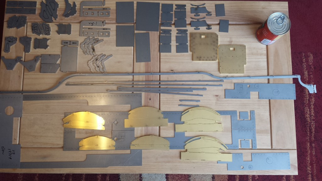
Before making a start on describing the construction of the expansion link bracket which deserves to be explained in detail. I best start with this picture which I forgot to post earlier. This is the result of John Baguley's CAD work, truly superb for accuracy to the drawings.
The parts here include the expansion link brackets, running board supports, rear stay, drag beam ends, cab steps, mudguards, cylinder mounting plates, running boards both outer's and inner's , raised cylinder boards, valances, cab floor, and finally splashers, a lot of metal that's for sure. Not cheap but worth every penny.
IIRC there was only one part that I had to discard and make the traditional way, that was the center front running board, not John's fault, he had drawn it exactly to drawing, just an error in the original design, I'll explain this when we get to these parts.
To cut out these parts to the same accuracy would have taken weeks, time much better spent in super detailing the model, IMHO, of course...:)
In case you hadn't guessed, I'm a big fan of modern technology, some things are just impossible to do by hand, that's when 3D printing comes into the limelight which you'll see later in the build.
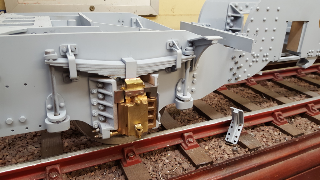
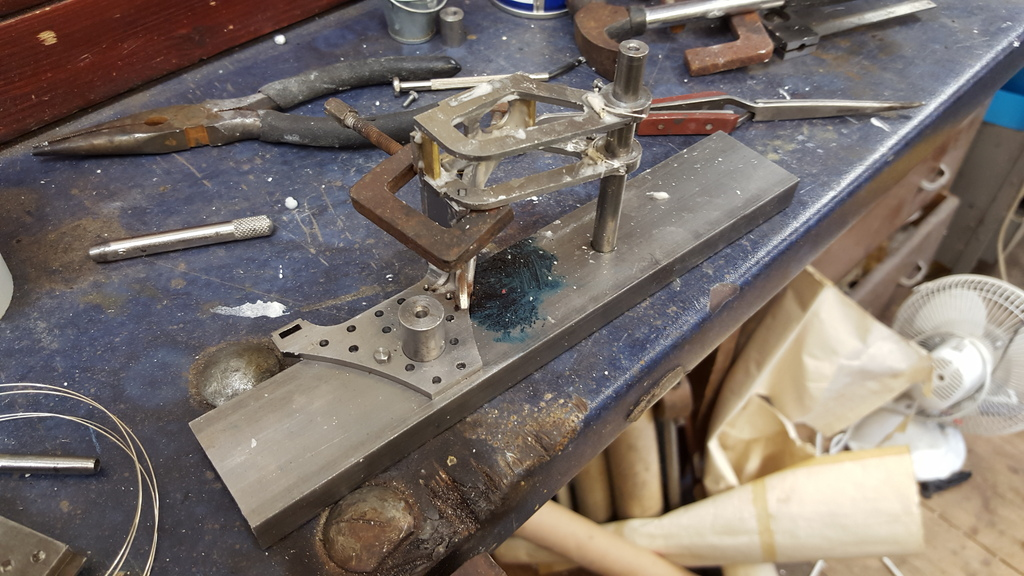
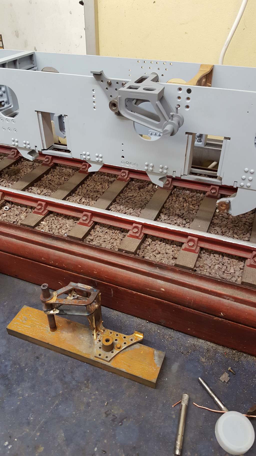
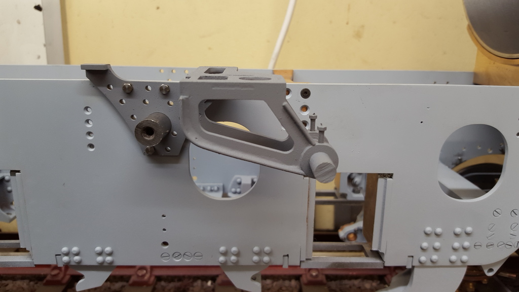
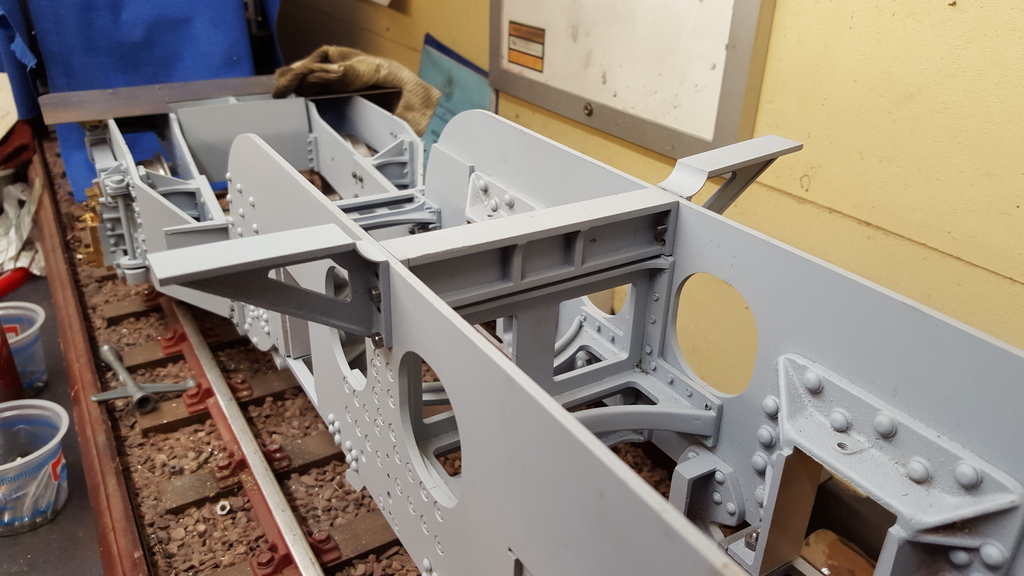
So, onto the expansion link brackets, these are seen here dry fitted to check for size and position. Having done some dimension checks I was very happy that these would do very nicely thank you, I'll need to make some jigs up, especially to unsure that the distance between the weighshaft and trunnion bearings ( 2 27/32) remains correct during the silver soldering process, I didn't want any errors here. The width of the bracket is spot on at 2.250 ( thanks John) so i won't need to do any in house adjustments here. As you can see I haven't removed all of the tabs yet, I will do this once I begin assembly, this way I shouldn't loose the smaller parts. I reamed out the 1/2" hole for the weighshaft bearings and also the triangular part of the bracket and then pushed some 1/2" bar threw both sides so that these parts were all correctly positioned and also that they were in identical positions on either side although a mirror image of each other. The plan was to mark out and drill the No.34 holes for the back plate first prior to brazing everything together, I'll make up jigs to hold the assembly square, spaced correctly and as mentioned have the two bearing centre's at the correct distance.
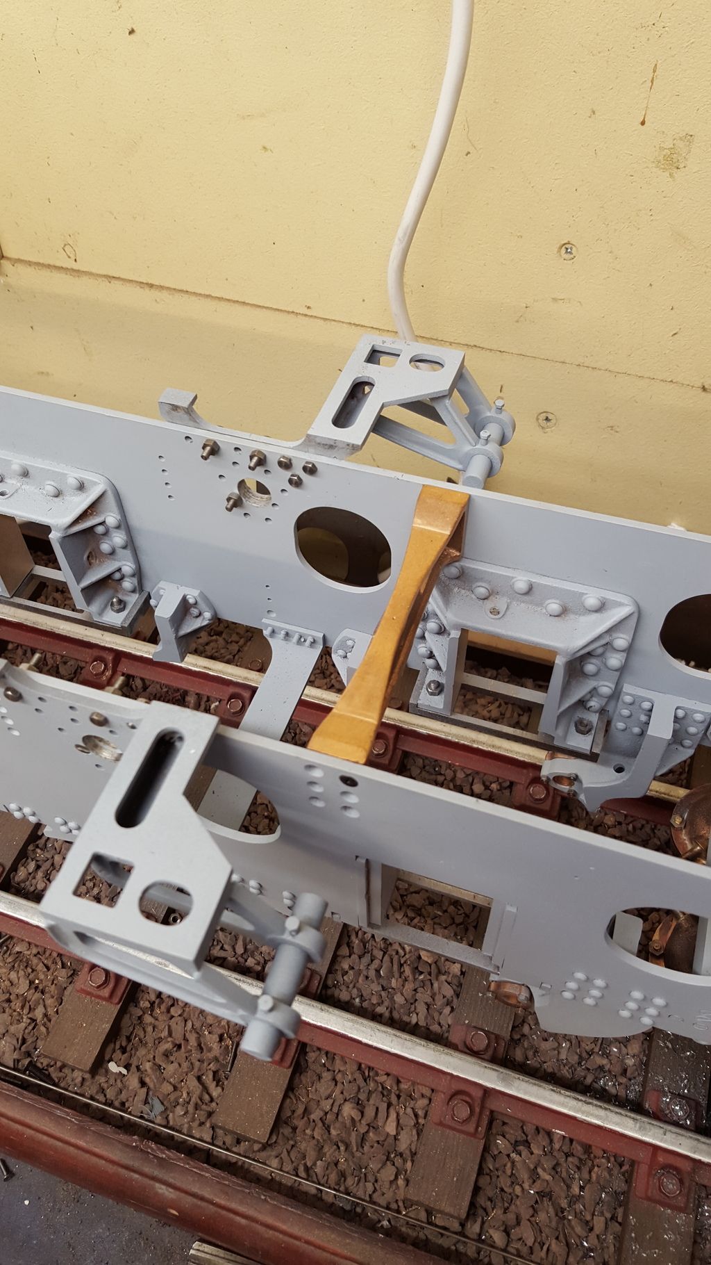
Anyway here's a picture to show what we have to play with, one other thing to point out here, I have drilled and tapped two holes into the inside motion bracket and fitted as seen in the picture, I won't fully fit this stay until the inside cylinder is done as this needs to line up perfectly with the inner slide bars.
NB: As things progressed I fitted the inside motion bracket anyway but left the angled mounting face for the middle cylinder motion bracket oversize until the cylinder had been mounted.
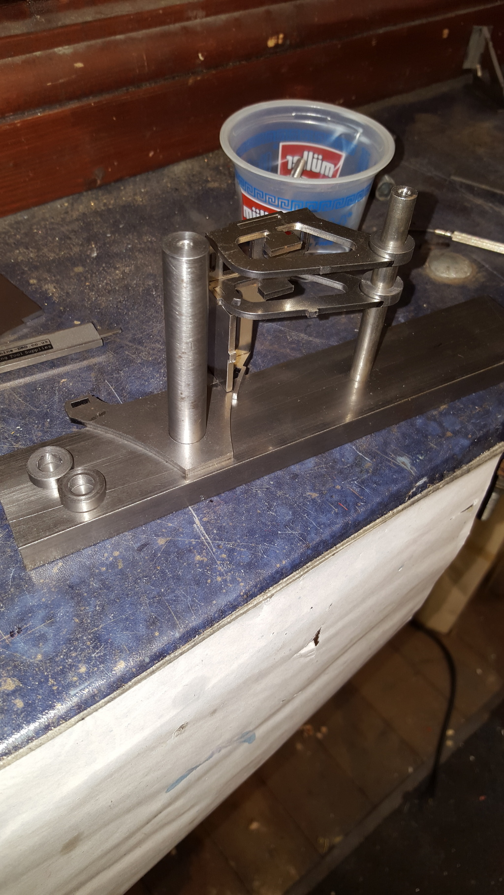
First picture is to show the unit assembled ready for heating, I mixed up the easyflow into a thick paste to give extra time. I made a substantial jig to help hold everything square and keep the two bearing center's at their correct distance of (IIRC) 2.8440 The two trunnion bearings are drilled and tapped 8 BA for lubricating oil cups which I'll turn up later, these came in handy for holding them at their correct heights above the jig base using a couple of 8 BA bolts. First bearing is 1.406 from the base and they are then spaced apart at 0.531.
here we have the unit silver soldered together, at first I followed Don's words and did this in one go but for the other side I did the top bearing support separately as I hadn't got enough penetration for my liking and had to reheat that area. I also forgot to attach the small running board support tab at the rear of the bracket, I made sure that i didn't do this for the next one...It takes a lot of heat to do this, mostly as the jig soaks up a lot of it but as long as everything is heated evenly first and then concentrated on the areas being brazed, all worked fine with good penetration.
after a soak in citric acid, I cleaned off the muck and got to filing down the excess tabs whilst also checking the joints for good penetration..
With the unit cleaned I then needed to add the raised ribs along the bracket edges, I did this using copper wire and soft solder to give a suitable fillet along the joint.
Here we have one side nearly finished and temporary bolted in place, the top of the outside bracket face needs 4 holes drilled and tapped 8 BA for supporting the running board. I have included the other bracket in the foreground, this just needs a good clean, tabs filed down and the copper edging formed and then soft soldered in place.
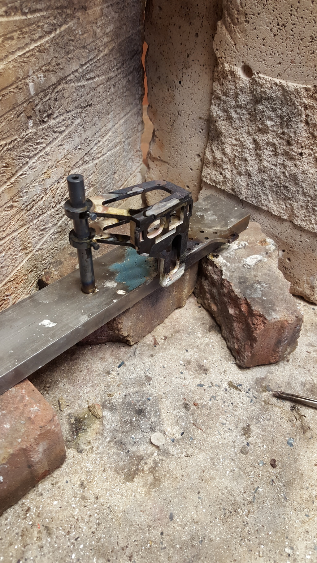
Although it's not easy to see I have sprayed the bracket with a textured finish primer, it actually looks very much to scale with a 'cast' look to it which is as per prototype so I'm happy, I'll also use this for any other fabricated items that should be cast, I used acid 8 as a primer coat first followed by Halfords texture paint, this paint takes enamel top coats so will be fine for when I get to that stage. I left the 5/16 bar in the bearing journals to stop any paint from touching their surfaces, same reason for leaving the two 8 BA hex head bolts in place. I took the close up in an attempt to show the texture finish but alas it doesn't really show up in the picture.
NB: I actually left the 5/16 bar in the bearings until the expansion links themselves had been made and fitted, this was to remove and risk of the bracket getting knocked, resulting in the bearings possibly being bent out of line, hope that makes sense?
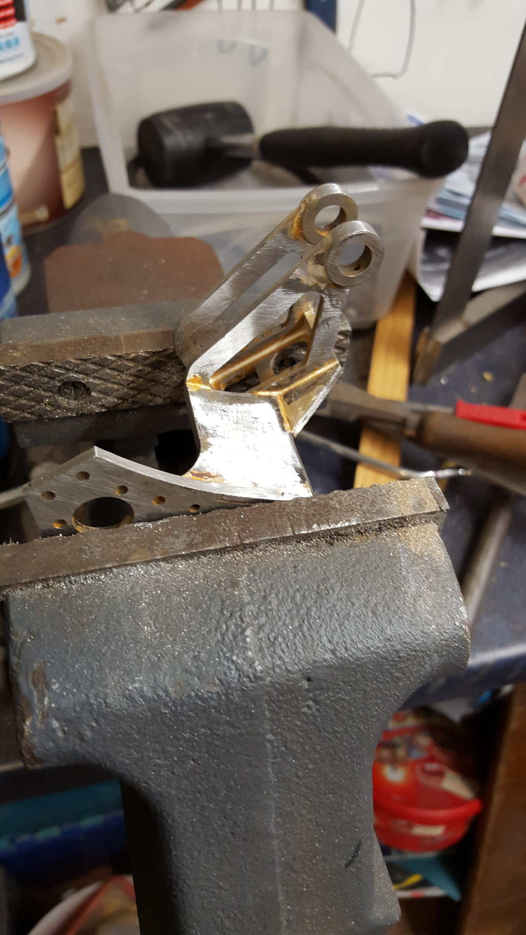
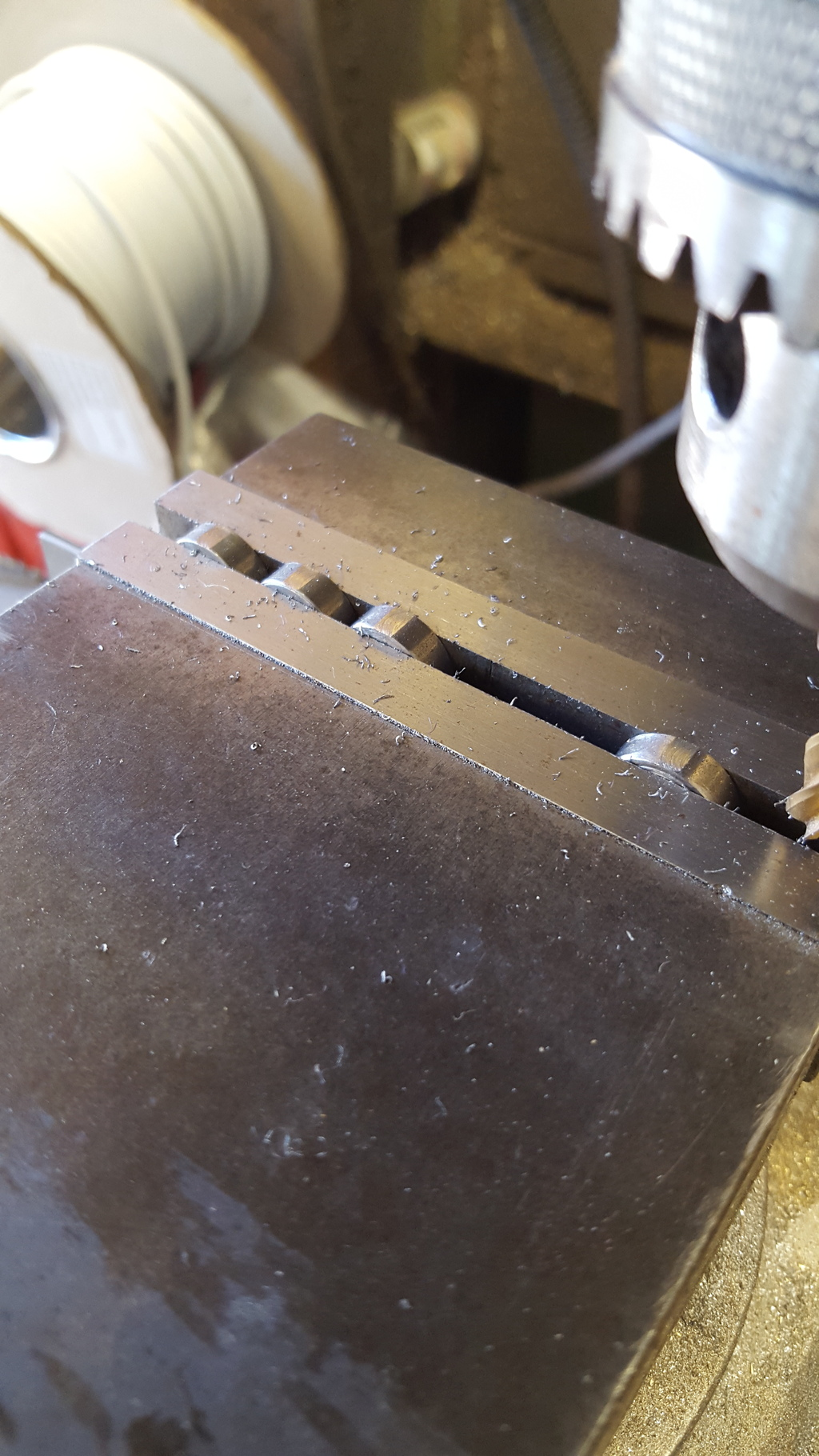
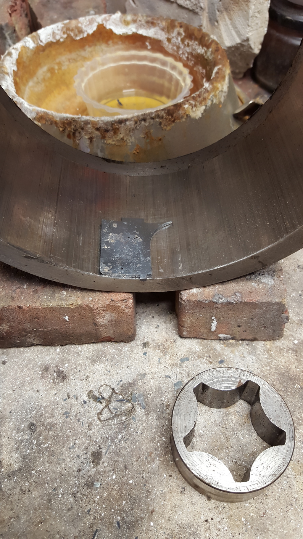
The trunnion bearing housings were simple turning from 9/16 BMS....3/16 wide with a 5/16 hole, final job was to cross drill and tap a 8BA hole ready for the oil cups, I decided to mill a small flat about 2 thou deep to aid the drilling and also give a small platform for the oil cups to sit on. Picture shows the setup in the machine vice..
NB: This is out of sequence, or at least I can't remember doing this after the parts had been painted, well I wouldn't have, so it's probably just how I originally wrote these notes up so look at this part as already done.
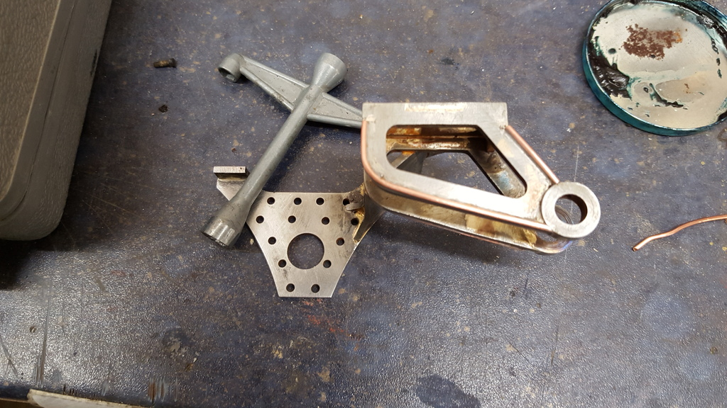
I found a couple of parts that needed some attention, the inner curved steel ( not seen in this picture as it needs heating and forming first) section of what's basically a triangular shape with a curved web at the bottom, needed some work on the web as it was a little large which meant it would later foul the mounting point for the weighshaft bearing. I can see where the error in the drawing has occurred and will pass the info on to Malcolm for correction, basically there are two arc'd webs and the radius has been mixed up between the two, no big deal, I simply ground down the curved arc to it's correct radius. Also the two spacers that fit between the two bearing support arms had been missed off the drawing although the slots for them had been cut, again no big deal i simply machined up a suitably sized piece of brass to have tabs that could fit into the slots, the tabs that can be seen in the picture still attached to the support arms are in fact for the rear support tab that I had forgotten to fit as mentioned in the earlier update.
The picture also shows the bearings having been set in their correct positions and the jig layout in general....a point to note is the jig has been constructed so that it works in reverse for the other bracket too, the 1/2" and 5/16" reamed centre's have been drilled right through on the mill along with the tapped 6 BA holes for holding the unit along it's correct axis( not seen in this picture as I haven't drilled the holes yet) , to do the other side I just needed to turn the unit over and push the bars through.
I formed the inner plate of the main support by using a smokebox cutoff as it happened to be close to the correct arc, a couple of heating sessions and the use of an old auto pump housing bearing sorted everything out satisfactorily, this is the web that needed re-profiling.
NB: sorry but the next few photo's are also out of sequence...should still make sense though.
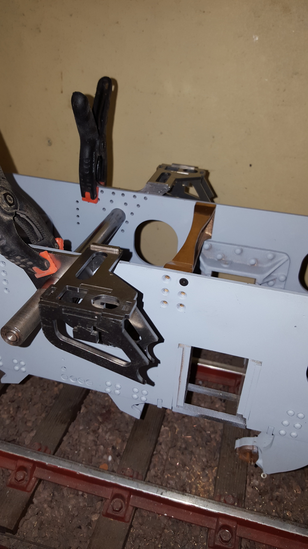
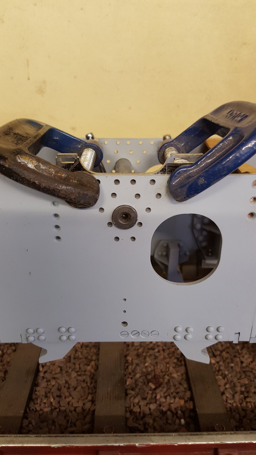
Now before I could silver solder everything together I needed to transfer the mounting holes, here I used a 1/2" bar to get the position correct and then mic'd the heights of the two upper parts to ensure all was level, using two clamps I first drilled one No.34 hole and fitted a 6 BA bolt, checking that all was still level I continued on to the next and so on until all holes were drilled. The 3 leading holes are different as they are tapped 6 BA rather than having bolts going right through them, reason for this is that the support arm sits over these holes which will be bolted from inside and thus not possible for bolts to be fitted.
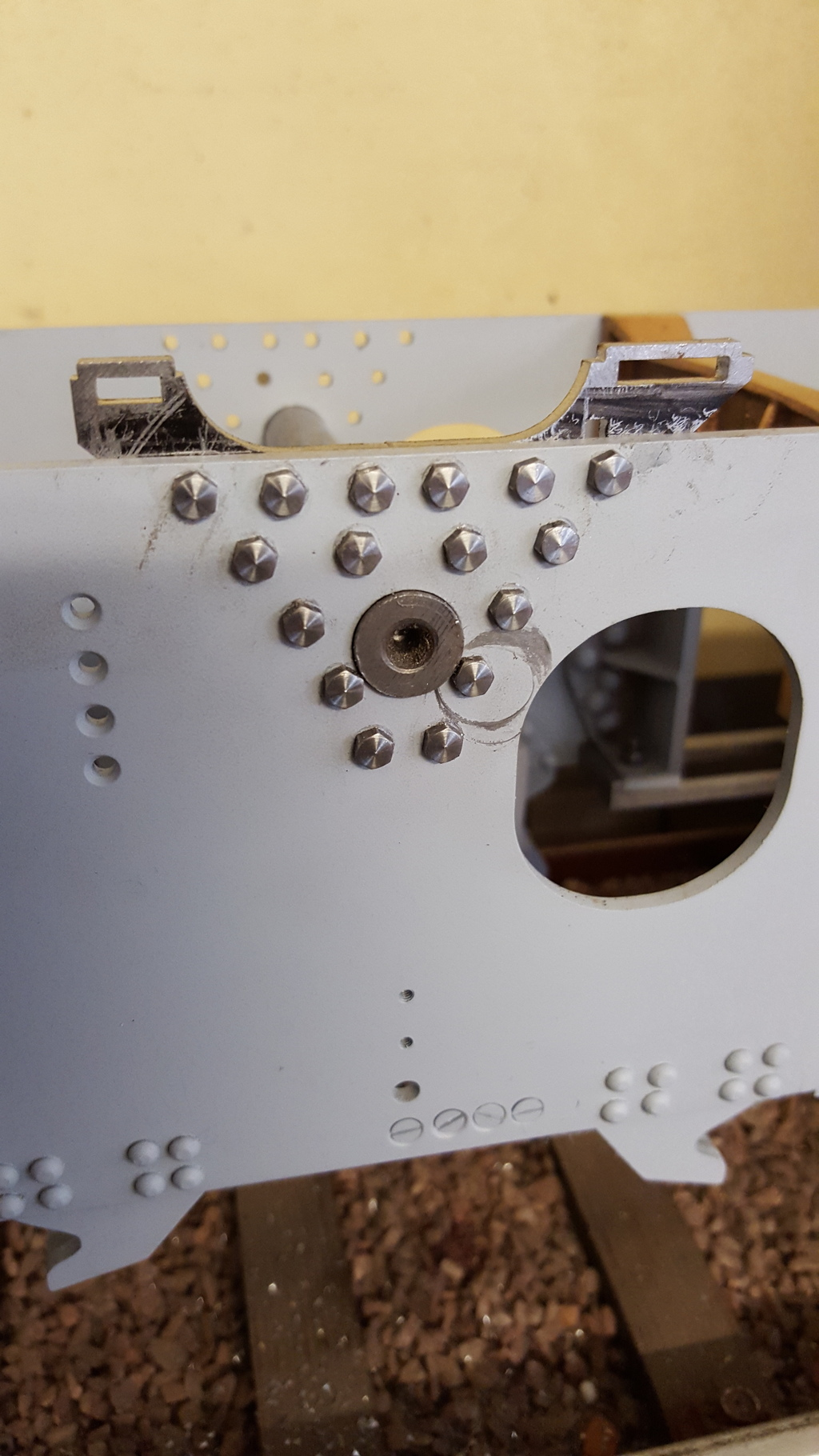
A picture to show that all holes have been drilled, as mentioned the 3 furthest to the right are tapped, and will be bolted from the inside, the second row up hole to the left will be csk hole in the bracket as it gets covered by the weighshaft bearing housing. I did both brackets on this side as both sides are identical so I didn't need to turn the loco around for the other side, it's also a good way of checking that both sides are identical.
After a fair bit of work we arrive at the completed expansion link brackets.

To finish this entry I'll cover a couple of the main running board supports. This is the main support which is in line with the star stay, a small admission here as I mistakenly placed the back plate level with the top of the frames for spotting the holes, forgetting about the curved section so the bottom holes are a little closer to the bottom of the plate than they should be, this hasn't proved a problem other than cosmetic and that's not in plain sight. I had to modify the bracket a little as the top plate was sitting too high, I can see where the error is and will report back to John and Malcolm in due course. The important thing is that the plate now sits at the same height as the expansion bracket, that being 0.312" above the top of the frames.
I have only taken a picture of the finished article as fabrication was much the same as other parts with the only difference being that I used a section of copper tube for the curved infill.
and now we have the rear supports....it's beginning to get very crowed in this area, there wasn't enough room to use hex heads so used slot less screws to hold the bracket in place, I have looked at a few of these brackets on full size now and they seem to vary, some have hex heads, others look like flattened rivet heads and some seem to have a mixture, brackets vary a little too so I'm happy to use what fits best. I will shave a small amount of the rear corner of the two top leaf springs for extra clearance, I'll probably do this when everything is stripped down for painting. I have placed the bracket for the other side in view to show what's involved.