There are a few bits and pieces that I'll include here just to tie up any lose ends around the frames before moving on to something more substantial.
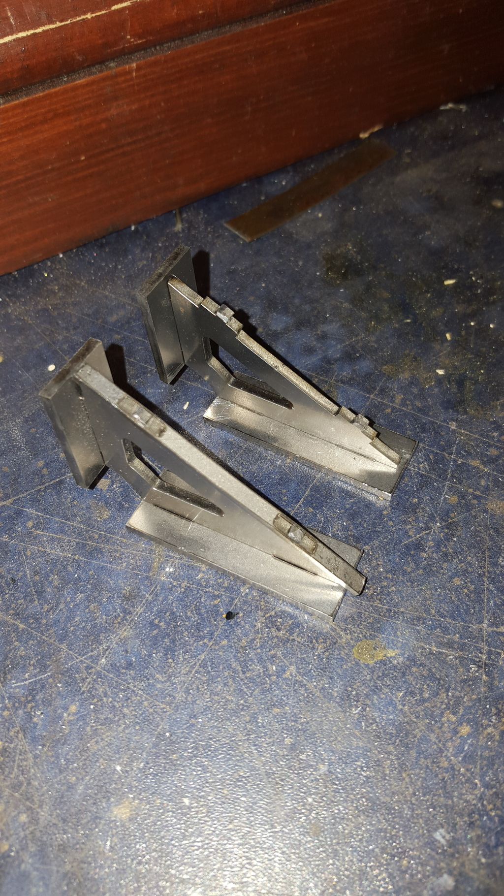
First up is the last stay to be made that fits between the frames, this being the rear stay that sits below the end of the firebox. I think that all laser cut parts from now on were drawn up for me by John Baguley and cut by Malcolm. John did a fantastic job for which I'm most grateful.
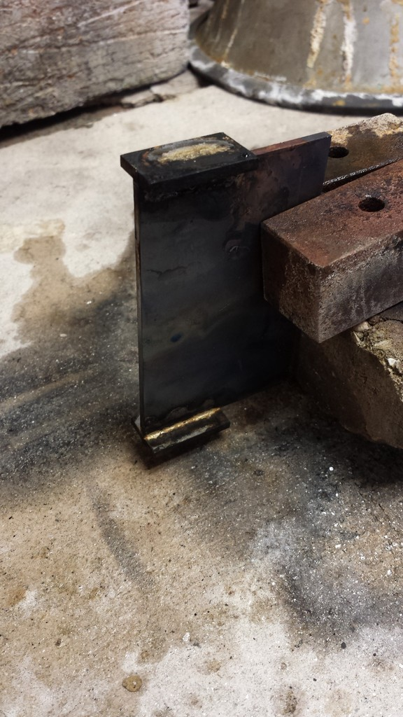
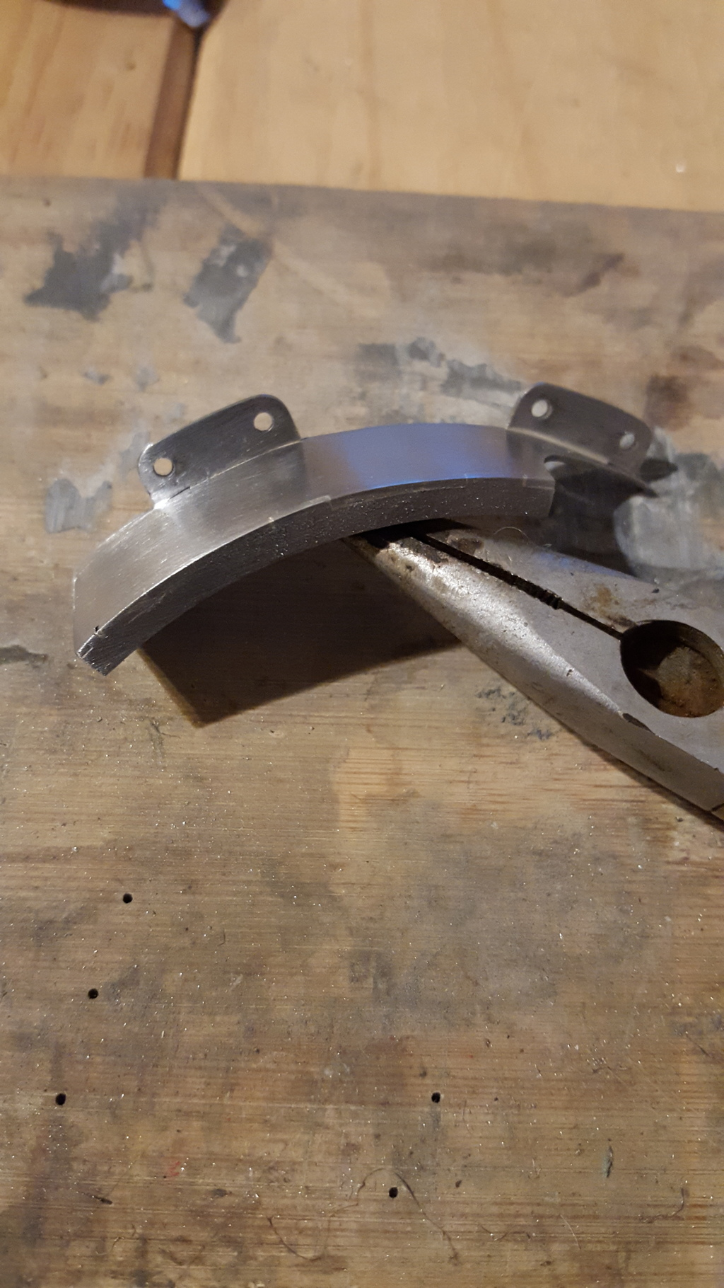
The point at which this stay fits the frames are angled so the tabs needed to have the same angle before being permanently joined to the stay. this picture shows my method of holding the parts while being silver soldered together, the parts are made from 3 mm steel.
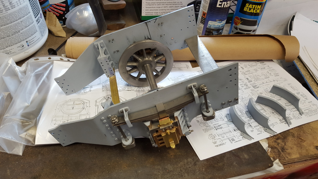
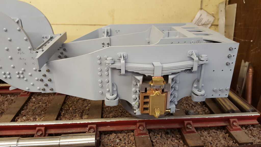
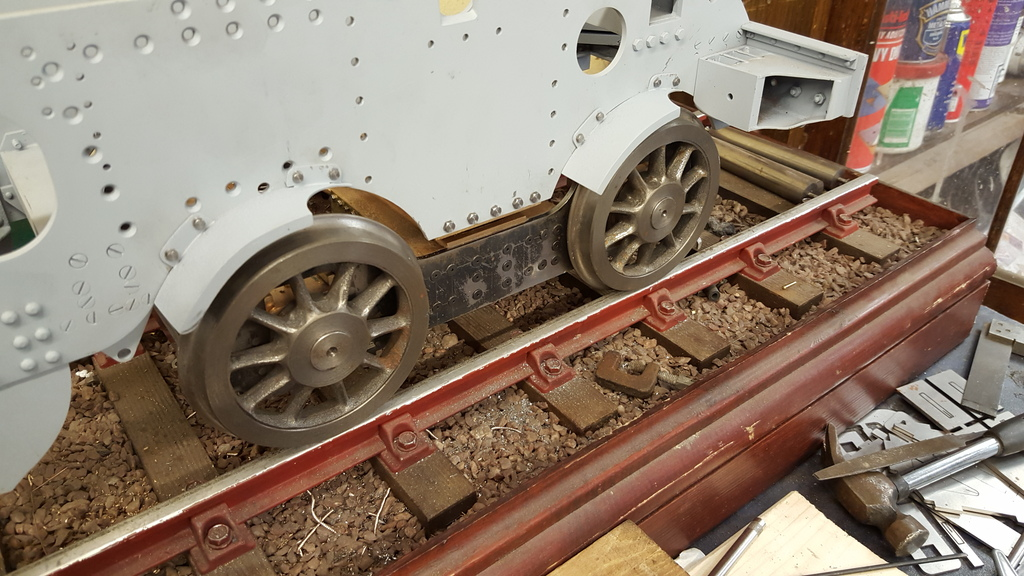
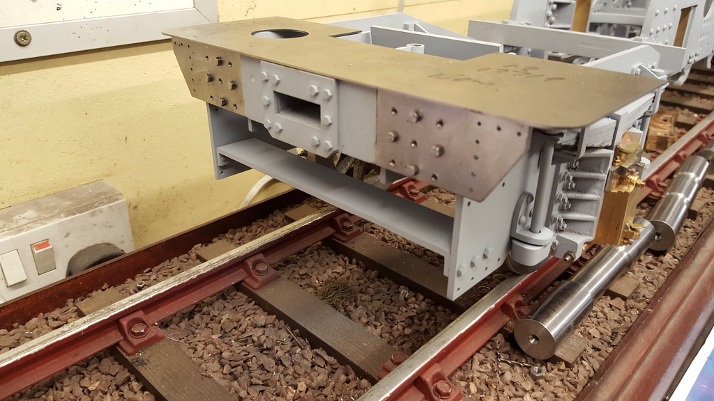
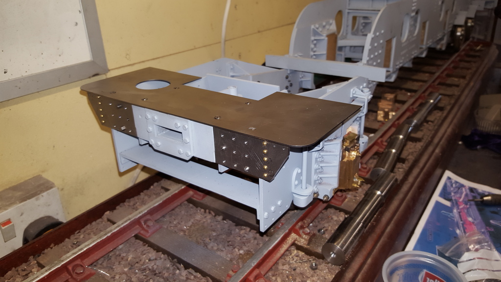
Now to fit the rear stay to the frames, meant first to dismantle the trailing frames and all their associated parts but while starting to take it apart I had an idea....to remove the trailing frames and cartazzi axle as a complete sub assembly. this worked very well and saved me an awful lot of time, also seen in the picture and a little out of sequence is the 4 completed bogie mudguards.
Here is the rear stay fitted, the rear of the boiler sits on both this and the boiler stay shown earlier. I also gave the assembly a fresh coat of acid 8..
Here we have the trailing frame assembly refitted after first also gaining some fresh paint...now i was kicking myself again here when I remembered that i wanted to fabricate the cab steps first before refitting the trailing frames as i needed to transfer their holes. However I later persevered and just drilled the holes using the digital scales on the mill to get the correct spacing for the 4 steps involved.
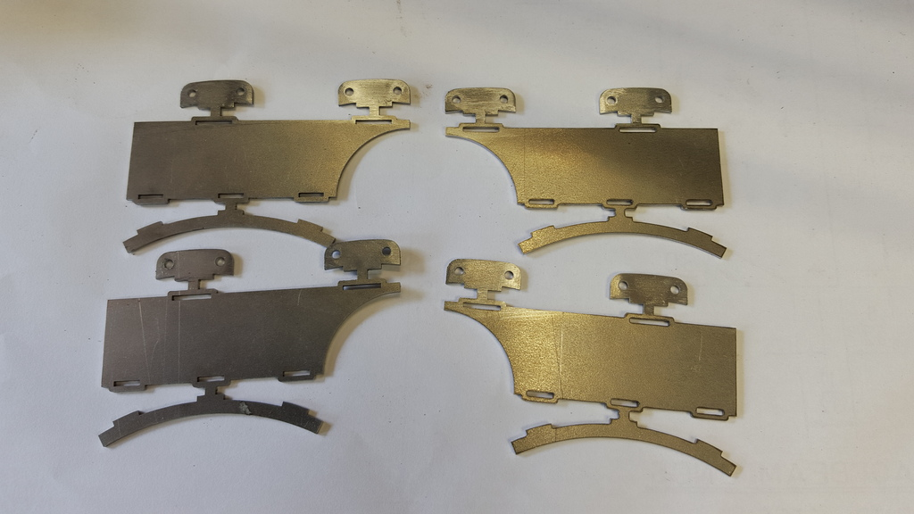
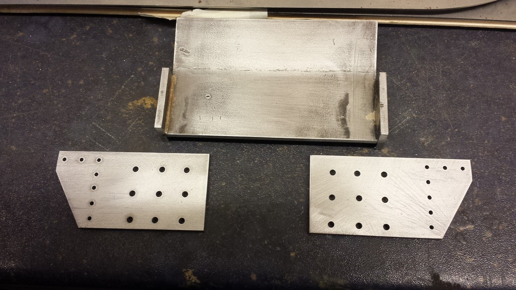
Now to the bogie wheel mud-shields, here are the laser cut parts as supplied except that I have already drilled the No.44 holes in the mounting plates before joining the parts as it's easier.
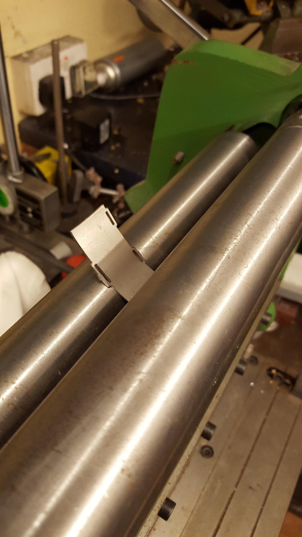
After parting the various parts the main body needed shaping in the rollers to match the curved sections and also the arc of the frame opening for the bogie wheels.
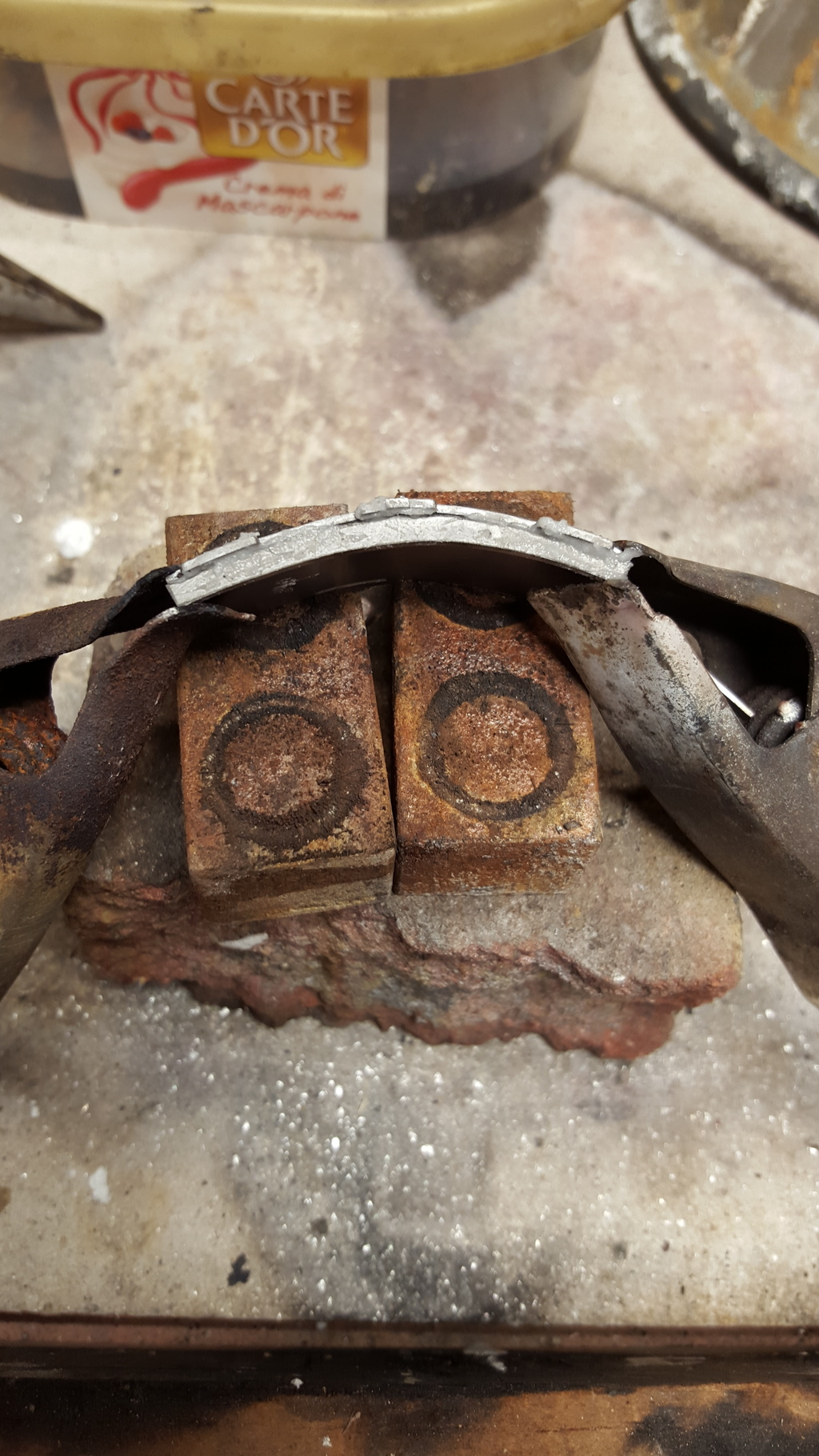
Next was to silver solder the parts together, first the curved arc that fits along the front edge followed by the two mounting plates that sit on the back edge.
Here's the finished article after some filing and sanding down with a 3M pad
Here's the four mudguards now fitted, the rear has had the lip profiled to match the prototype, I'm sure that I've mentioned before my hatred of drilling and tapping 8 BA holes in 1/8th steel and this was no exception, luckily I had no mishaps but it's a nerve racking experience all the same when doing so on the frames as built rather than on a flat plane...problem is I still have at least another 100 holes this size to do in the main frames alone...gulp!
NB: Also of note is the completed buffer housings and buffer beam
This picture shows the fabricated stay, again out of sequence and also in this picture are the two dragbeam ends, these have been drilled for 1/16 snaphead rivets on the outer angled edge and No.41 for 7 BA bolts to attach the beams to the rear stiffeners, these will be clamped in situ and the holes transfered and tapped 7 BA.
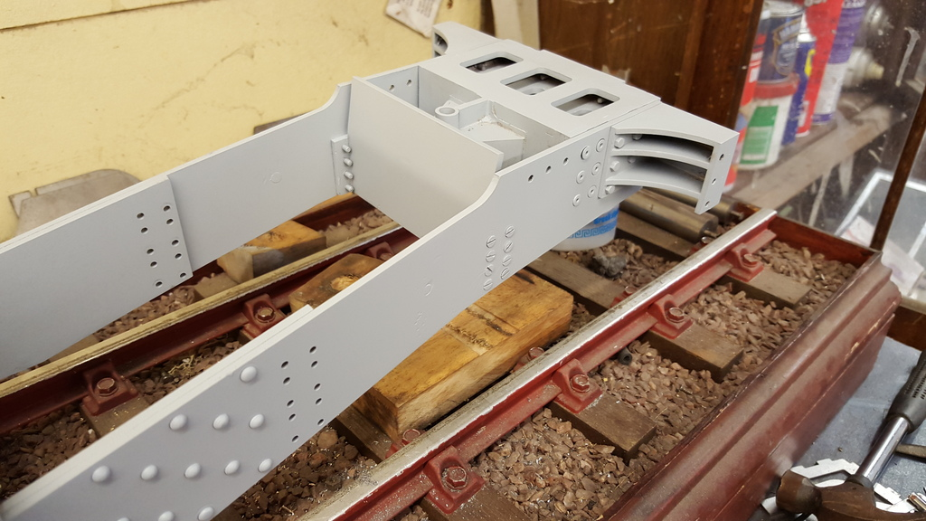
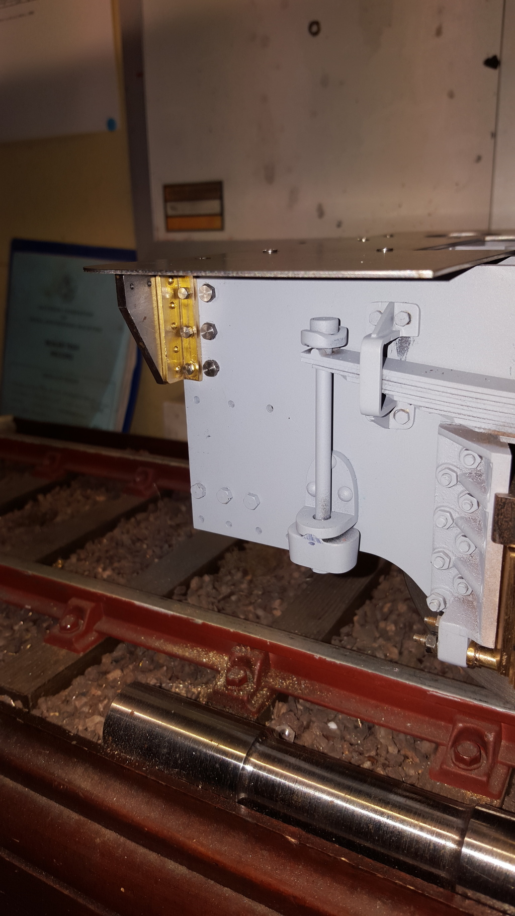
This picture gives a better idea of the rear stay in it's correct position, it's a snug fit so holds itself in place, I later transfered the holes once the trailing frame assembly had been removed, Note that the top edge of the rear stay is angled backwards, this is a distance of 5/32, from the vertical, I thought that it may have needed tweaking once the boiler was fitted but it proved to be correct from the start.
IAt the same stage I also found time to do a little on the back of the loco, in this case drilling and tapping the eighteen 7 BA mounting holes for the drag beam ends. The hex head bolts are only temporary, the prototype has rivets here so these will be changed for round head 7 BA screws....
NB: I later turned down the heads of said screws to be more to scale and then filled the slots.
On taking a closer look at the front bogie spring rate I decided to upgrade it's springs as to me they didn't seem strong enough for the weight load involved, yes they are still working but there's still an awful lot more weight to add to the front of the loco before it's finished. I ordered 10 @ 3/8 x 1" 17swg spring from Kennions for testing
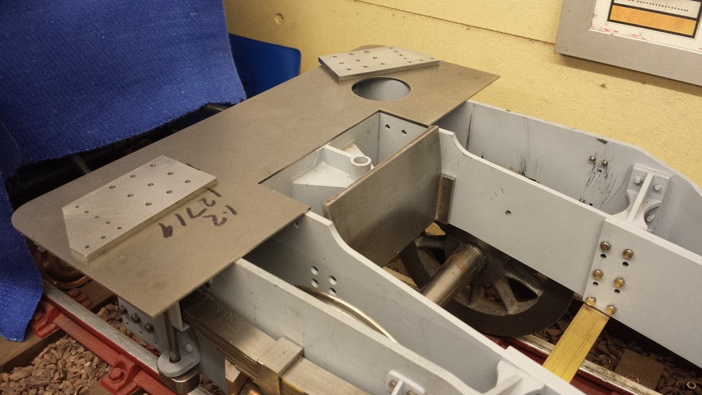
Next I fitted the cab floor, As can be seen I have done the smaller vertical row of rivets that hold on a right-angled support fitted behind and also bolted to the trailing frames with 3 8 BA hex head bolts.
A view from the front showing the right angled support, in this case made from brass 1/2" right angle with one face machined down to allow clearance for the larger 6 BA hex heads. As per usual the brass angle wasn't properly square and so was machined true first. The two horizontal holes seen along the top of the drag beam end are for rivets to hold the valance that curves around the back, Instead of a permanent fixing with rivets,when I later got to the running board valance I used 8 BA round head screws here. More on this later...
I began dry assembly of the main running board support. However having dry fitted the parts I had and offered to the frames I thought it prudent to make the side valances first, reason being that the running boards sit higher than the main frames and I want to be very sure of the support heights before drilling and tapping all those 8 BA holes.
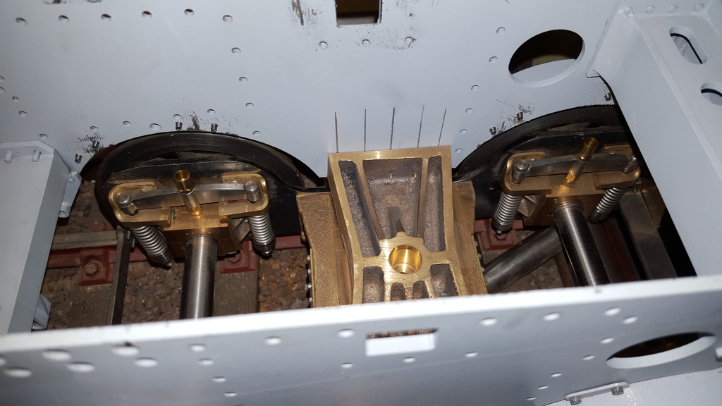
Lastly going back to the front bogie, if you recall I modified the spring yoke and axle box with an oil feed-way to lubricate the axles while in service, saving the need to drop the keeps to get oil onto the oil pads. I just needed to fit oil cups to finish but didn't do so until after the mudguards were fitted to be sure of clearance, as it happened I needn't have worried as there's plenty of room. I had considered fitting oil cups with lids but I wouldn't be able to get to them while in the steaming bay so have used the open topped design instead. Due to their close proximity to the smokebox I will put oil soaked cotton gauze into the cups to stop any ash from getting to the axles and their important journals.