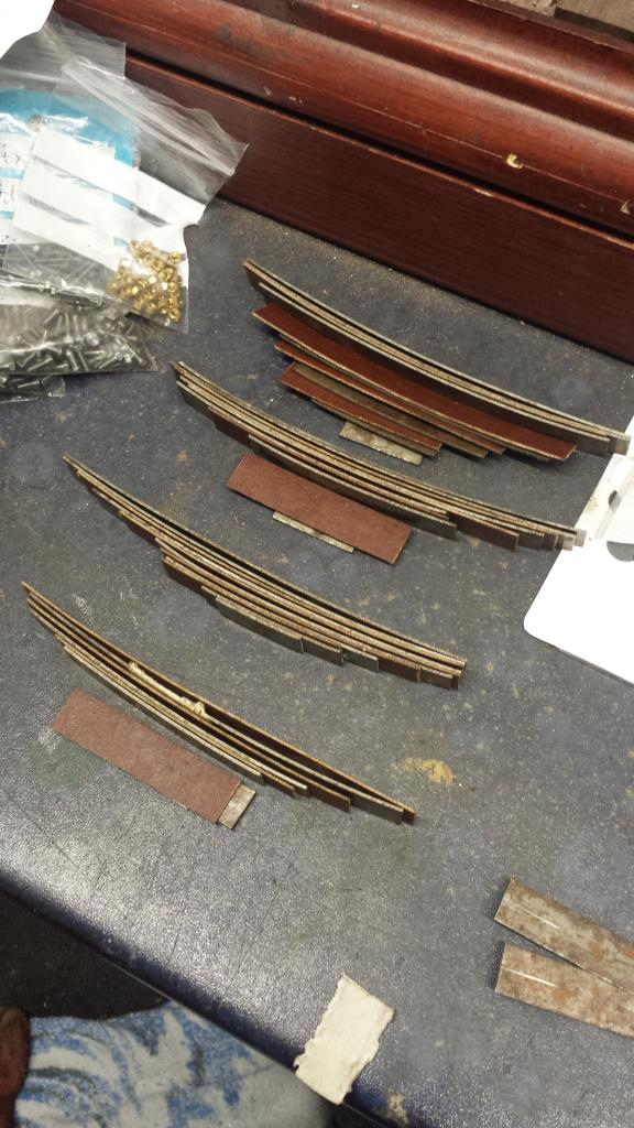
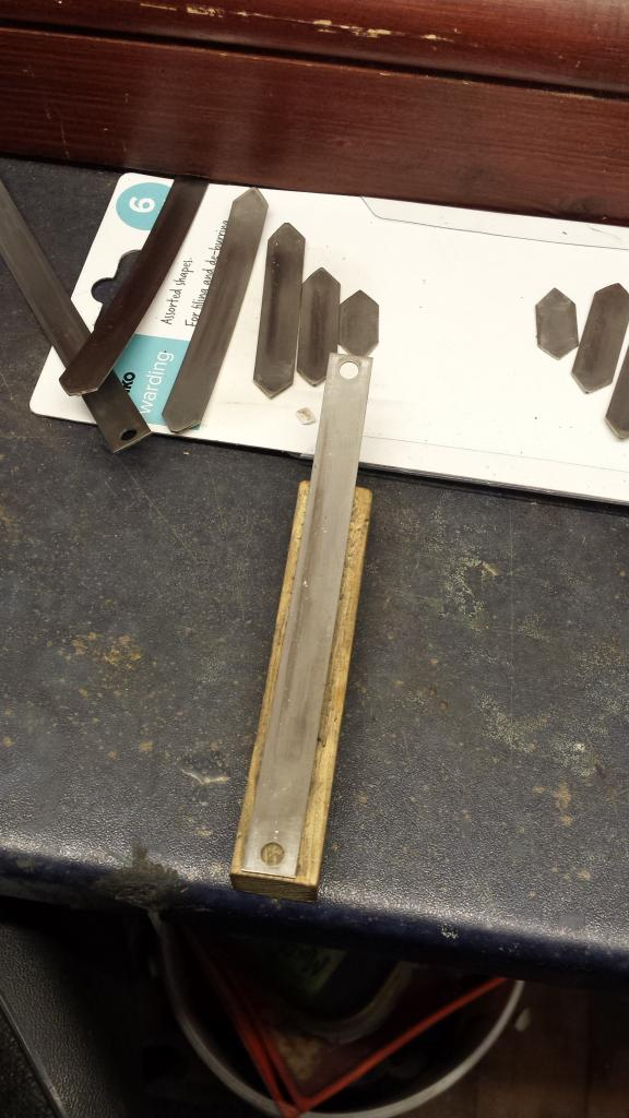
Springs are the topic for this entry, I haven't taken pictures for all the construction as some of it was just a repeat of the tender springs, but there are differences which I shall cover. First off I cut all the springs to length, as with the tender they are a mixture of sprung steel and tufnol...the picture shows the cut lengths and a clear school boy error....yep I cut 4 sets instead of two, oh well must be loosing my mind.
NB: I don't think that my mind has got any better since..:)
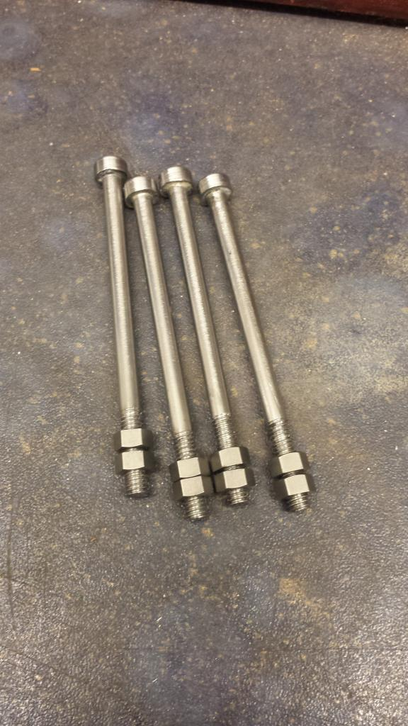
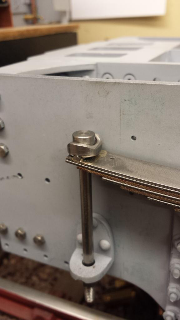
Now we come to the main difference between the tender and cartazzi spring sets...the tender spring hangers are hooked and slot over the end of the spring and latch onto the gripper( lovely design) that is brazed to the end of the top spring, whereas the cartazzi spring hangers are a simple design in comparison being a straight length of steel which a collar at the top and threaded at the end as shown here.
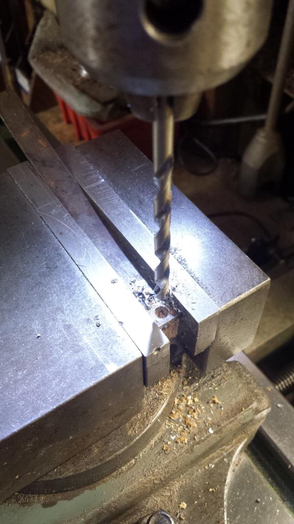
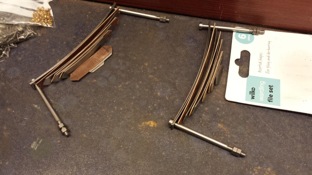
Now whereas the spring hangers are simpler, the spring leafs require a little more work, the top two springs are drilled no.12 @ 5/32 in from each end and a 3/32 steel gripper needs to be brazed across the centreline of the hole, the gripper is first machined to half it's width leaving it flat along it's length, ie half round. Material required is steel. I drilled the no.12 holes first as seen here, each upper set being drilled together.
I then Chamffered all of the leaf ends except the first 3, top two steel leafs having straight ends and the third leaf has a small semi circle filed out of each end for it to fit up against the spring hanger. Next I dug out the hardwood profile tool that I had made for the tender springs to shape the leafs to their required 1/4 deflection, followed by a good polish ready for the hardening treatment. This was the same as described for the tender....heated, quenched in mineral oil, tempered and cooled resulting in lovely flexing spring leafs. Last job for the top springs was to braze on the grippers using the same trick Don described for the tender, ie push the leaf into a large potato with just the end sticking out for brazing on the gripper and thus protecting the treated steel. Picture shows the leafs during shaping....
Here we have the components so far.... next job was to do the spring buckles which again are the same as for the tender, I forgot to take a picture of these but it's covered in the tender build.
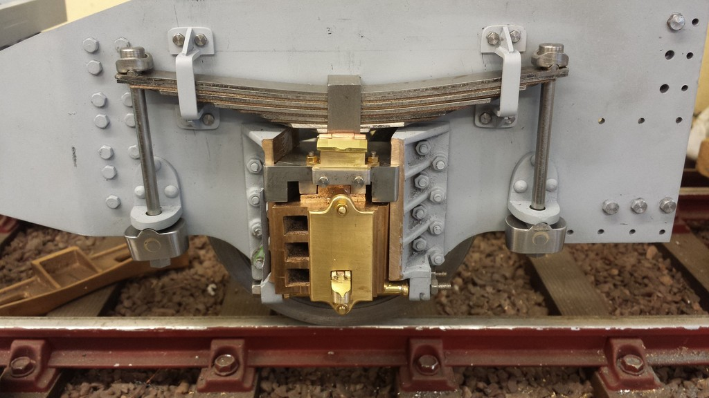
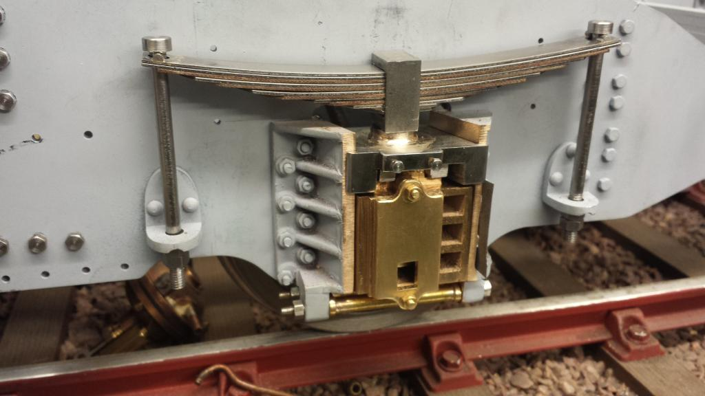
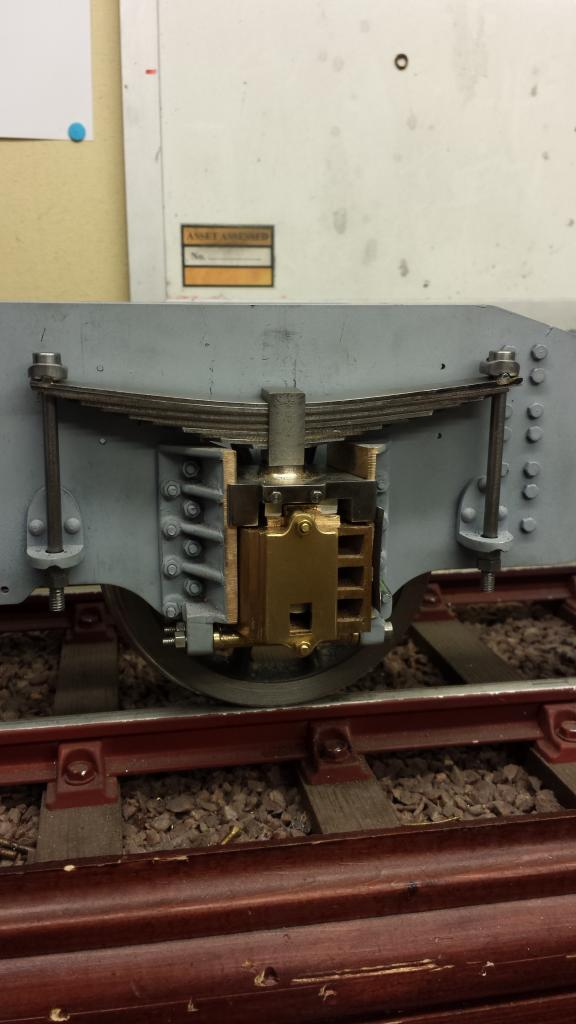
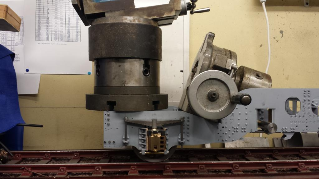
And this is where I have got to so far....it was nice to discover that the springs not only worked well but the deflection looks like it's correct, currently sitting about 1/4 higher than normal which will settle once the boiler is fitted. I will of course have to test the spring settings when fully loaded, either adding or removing tufnol for steel and vices a versa. Close up on the progress so far, two big jobs left to do still on the springs... the spring washers that fit between the top spring and the bottom lip of the spring hanger being held in place via the gripper, which in turn fits into a recess in the bottom of the spring washer. Lastly I still needed to construct the shock absorbers, not a five minute job that's for sure...
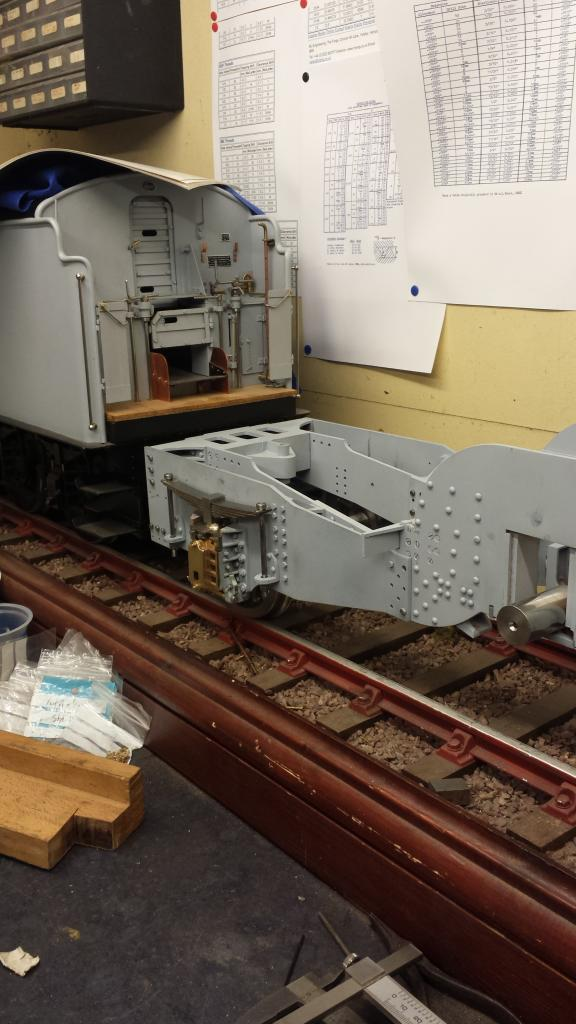
Here's a long view to show the current riding height, I also adjusted the bogie springs to increase the height a little to match what I now thought was the correct height for the chassis to mate with the tender. There is a note in Don's words that one of his test builders thought the main springs needed less tufnol to be able to support the engine weight, the note states that the guy was going to test this during strip down for painting but there was no follow up, so I'll need to remember this when I do the main springs.
NB: As the build continued it was clear that the chassis was sitting too high at the rear, the springs were too strong and thus some steel leafs were replaced for more tufnol, these changes were done much later as the model progressed and the boiler had been placed on the frames, more on this later.
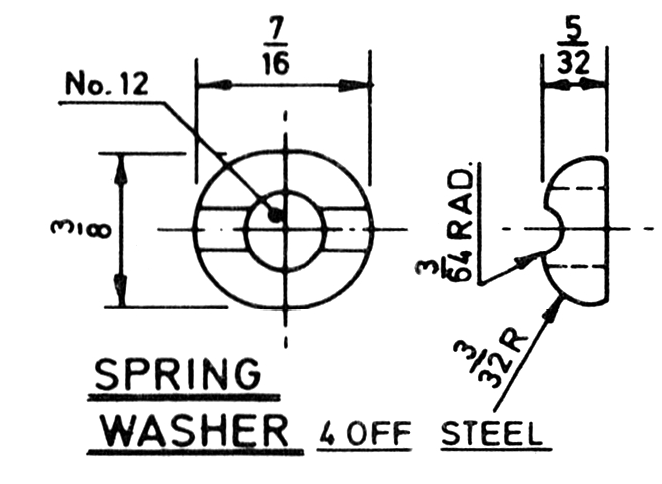
I was going to leave this update for the spring washers until I had done the shock absorbers too but these are rather involved little buggers and needed a few pictures to show how I made them. Here I have deviated greatly from Don's drawing, nothing new there but in this case the drawing didn't look very much like the prototype so I've followed as close as possible (without wasting too much time) the various photo's in my collection.
First the drawing.. the overall dimensions of 7/16 x 3/8 x 5/32 I have kept, it's the profile and detail that I have changed, being an oval shape they are not plain turning so I have approached the job in a way for me to get 4 washers the same mostly via machining for speed and finished with a little filing.
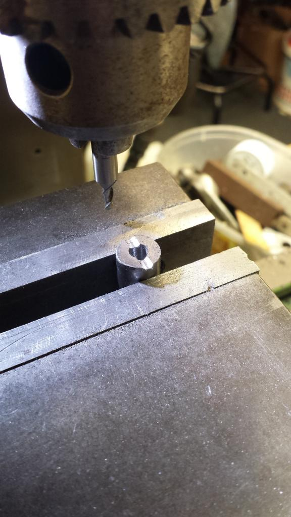
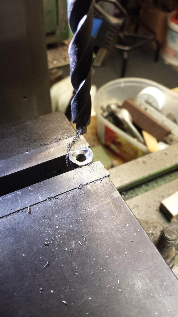
I'm not going to show pictures for every process but will describe each as I did it......using a length of 7/16 BMS bar I held it in the 3 jaw, centre drilled and then drilled No.12 hole deep enough for me to cut off a 1" length, repeated to give me two pieces, 1" was chosen as it is deep enough to be held in the machine vice with enough material sticking above the jaws for working on. After deburring, each section was placed in the machine vice, centered and then had it's semi-circle recess machined across it's width to match the gripper on the top leaf spring. I then simply turned over and did the other side, same with the other cut section. First picture shows the first groove cut..
NB: I have reread this paragraph and for the life of me can't fully understand what i was trying to say, sorry about that guys, hopefully the pictures make sense.
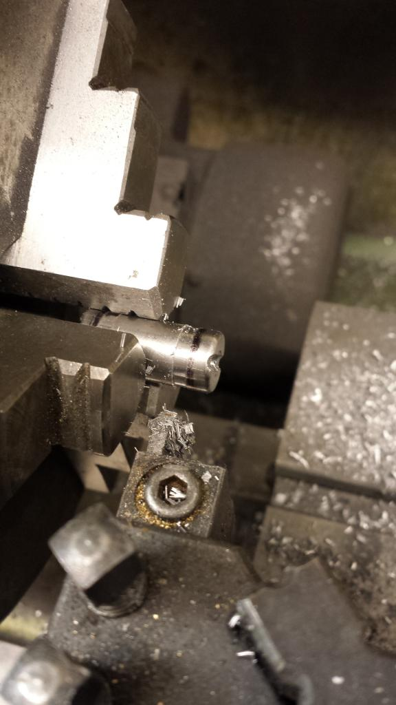
It was then back to the lathe where parting at 5/32 was marked but not completed, this is a visual aid for me to get the rounded edge of the bottom face as per photo's, once done the section was turned around for the other end, same for the second.
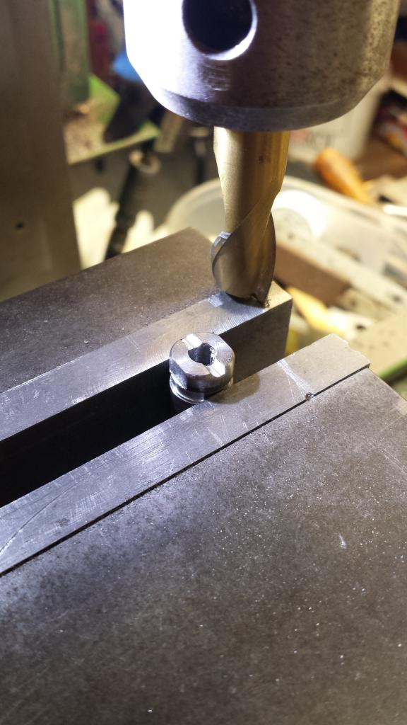
Back to the mill for machining the oval to size, I took 30 thou of either side, leaving a small amount to be filed by hand as the oval was rounded off.
The sections were then returned to the lathe and fully parted into 4 washers, back to the mill again, inverted and then a large recess was filed using a half round file and then a step drill of a suitable size for the no.12 bore, the width of the spring hanger collar was used to give a recess for the collar, I only had a drill bit that counter sunk the recess a little but this wasn't an issue and it's hidden by the collar, plus for all I know there may be a counter sunk there anyway to allow the collar to tilt...well it makes sense to me....
Next followed a lot of hand filing and the use of the belt sander, these parts are pretty small so I held each part with a suitable nut and bolt, got a little hot on the belt sander though....
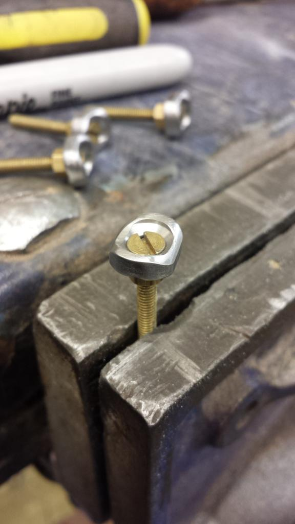
To finish off the spring washers here's a close up of one of them fitted, I have to say that I'm pretty please with how these turned out, when compared prototype pictures posted previously they look pretty close and certainly a lot more prototypical than those drawn by Don... worth the 3-4 hours they took to make.
NB: Now when I came to this part of the log I remembered that not only was the tender spring thickness given by Don wrong but so was the dimension for the trailing axle springs. I can't recall if I mentioned this for the tender but I have used the full size dimensions and scaled down, using Don's size results in the springs stack not filling the buckle slot as they should do.
Anyway, I decided to do a little test...well curiosity and all that....I loaded up the chassis until the spring was sitting at it's horizontal position or at least close too , I could still push it down a further 3/16 to 1/4" to check it has movement and is thus sprung...seems about right. Once I was happy with the ride height ( the back is presently sitting about 1/32 higher than the front, still not horizontal with the springs and I haven't set the front bogie springs ride height yet but it's in the ball park of where I need to be) I weighed the various components used for this height...came in at 101.6 lb... I estimate the loco alone to have a weight of between 180-200 lb. Anyway I was happy with how things were progressing to this stage in the springing department, lots to play around with still considering the main springs still needed doing...
The Shock absorbers are the same as those on the tender so no need to go over those again here, a picture just to show this stage completed.
I then made a start on the oil reservoirs...I'll show the drawing to explain things easier..
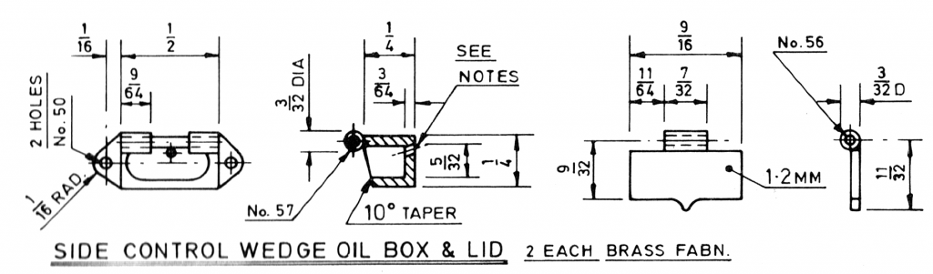
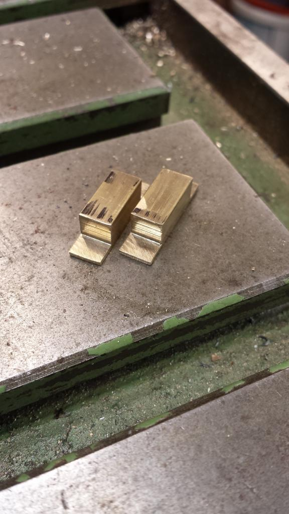
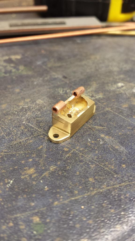
The first job was to make the reservoir tanks from 1/4 brass section, once i had two rectangles of the correct length I machined the end steps that have the holes for the bolts to secure them to the spring plate, as per drawing and as seen here.
after some machining, shaping and silver soldering on the hinge we arrive at the nearly finished tank, top is sloped 10 degrees, hinge has been added and the end tabs have been profiled to shape although not quite there yet, I also needed to do a little more draw filing to get the case nice as this isn't a painted item when finished remaining brass so needs to be good. Oh and the small oil hole has been drilled into the bottom of the tank at an angle...this hole will continue through the spring plate and the wedge so that all of those parts get oiled from the one tank, this I did once the tank had been fitted to the spring plate.
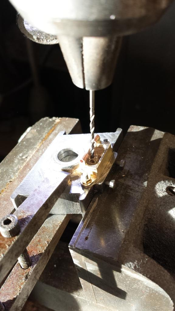
Next up was to bolt the tank to the spring plate and then drill the oilway hole, this being drilled at an angle through from the oil tank, through the springplate and then also through the sideways control wedge. Before I could do this I needed to mark and drill the two holes for mounting the oil reservoir which is held on by 10 BA studs.
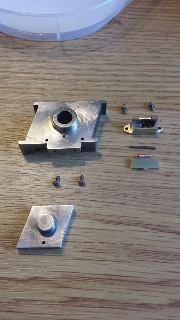
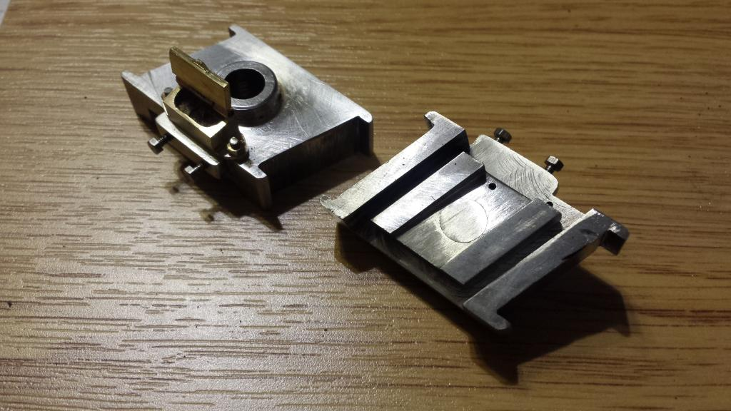
Here is a view of the various parts that make up the springplate assembly for the cartazzi axle, lower item is the wedge, you can clearly see the oilway hole which is off centre, above is the 2 10 BA bolts that would hold on the dust shield if fitted, this seems to be a later item, as mentioned earlier, I haven't seen the shield itself on pictures from the era I'm modelling although the bolts are seen. Above that we have the springplate, this is different to the plate on Tornado today as it has the shelf that sticks out partly for the oil reservoir, Tornado seems to have a different shaped reservoir. Note the two holes at the front for the shield bolts, two holes on the top face for the reservoir studs and also the central oilway hole. Lower right is the reservoir lid, above that the hinge pin followed by the reservoir and lastly the two 10 BA studs and nuts.
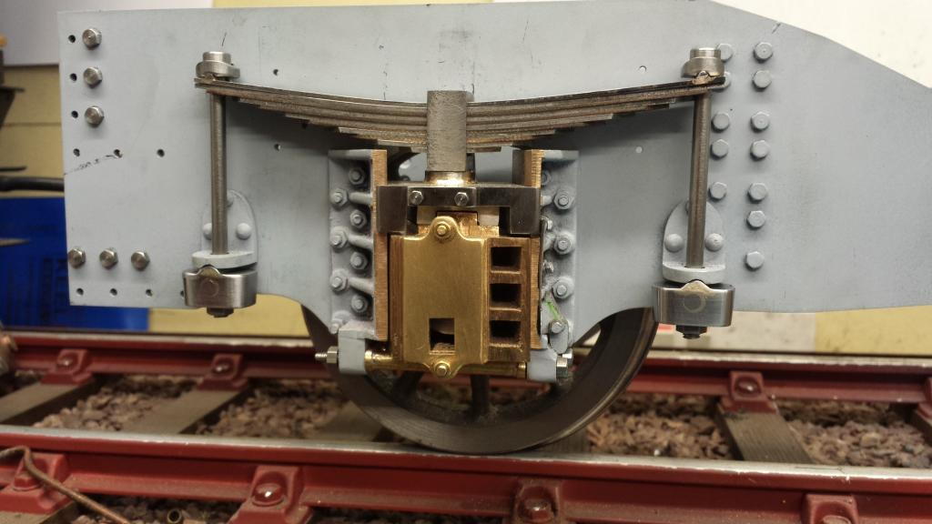
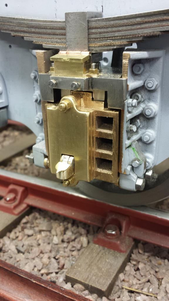
Close up of the finished assembly, I spent a bit of time filing these parts which shows when compared to the other cartazzi parts that still need a lot of work doing to them.
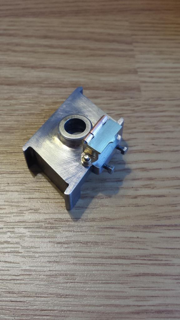
I included this view to show the top and bottom assembled parts together, hopefully to give an insight into how this all works, top is self explanatory, bottom gives an idea of the pivoting movement for the wedge in relation to its position in the springplate recess and the oilway that multitasks supplying oil between the springplate and wedge above but also down between the wedge and the axlebox below.
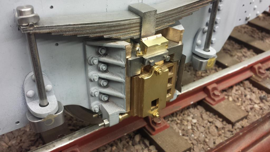
And now the assembly shown back together, here it really shows how much more tidying up I needed to do on the rest of the cartazzi parts, that was for another day....
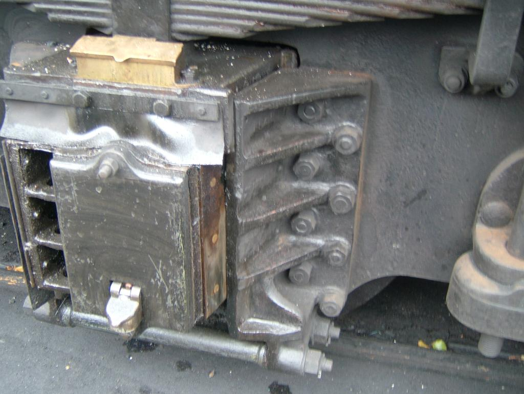
To conclude this session a pictureof a full size cartazzi axle to show as a comparison...this is the other side though, alas the model was facing the other way and I didn't really want to try and move it alone at that time.
And here's the model so far....
NB:I made some changes after this picture was taken, well not changes 'per se' just a little more fettering, I reduced the thickness of the oil tank lid, shortened the studs and replaced the bolt that's been knocked and thus bent. Everything also had a good filing to remove most of the casting and machine marks, plus the spring leafs were tidied up (aligned), plus some final filling before painting. In fact I seem to be forever making good on various parts, I guess with literally thousands of parts to make lots need tidying up later or you'd never get anything done, my list of 'things to do' is pretty long and still getting longer.
NB: There was still one part missing in the picture above as they weren't detailed on Don's drawings although he did include something on the GA but it looked nothing like the prototype, these were the spring retainer brackets. These were simple fabrications so no need for me to go into detail other than to point out their presence. I did some research before making/fitting these as they were not on most of my reference photos from 1920/30's. However I could see them clearly from 1936 onward and thus within my time-frame and so had to be included on my model.