

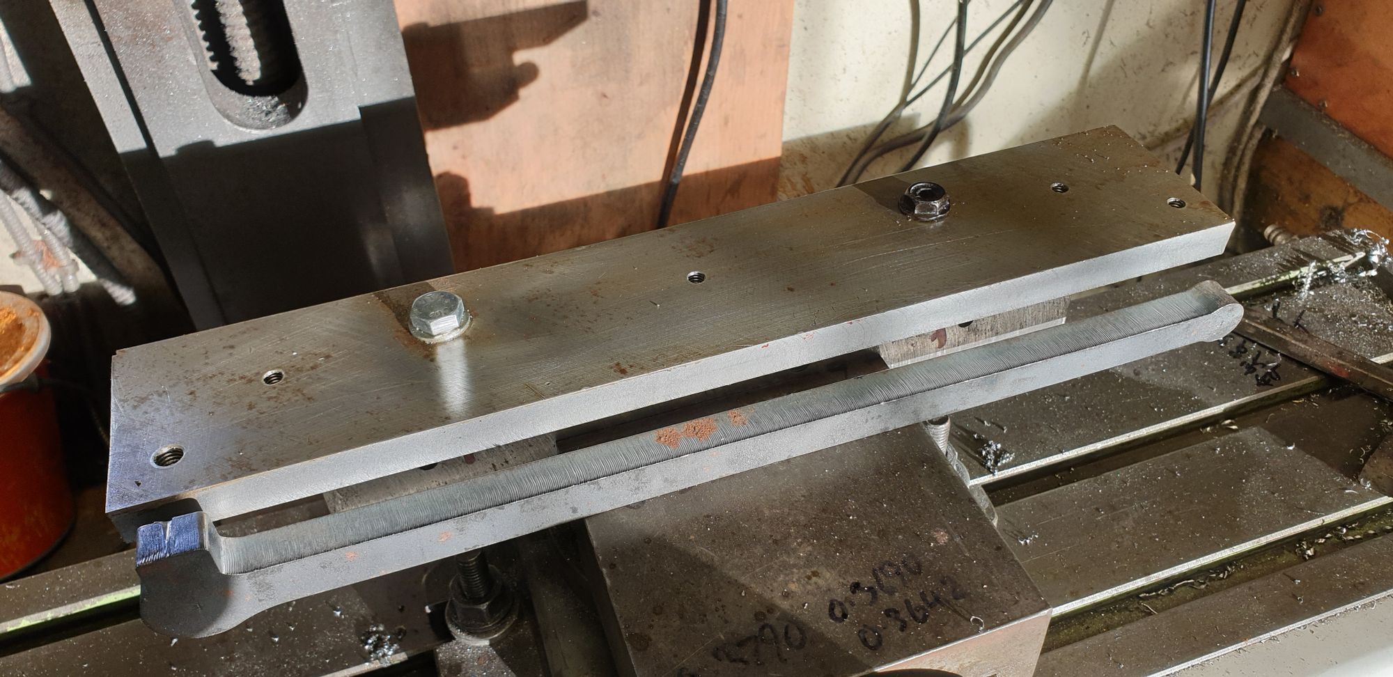
On to the outside connecting rods, these are the longest of all the motion parts, they are fairly slim too so I needed my trusty jig (block of solid steel) again plus another 1/2 thick section bolted to it to give me a large enough supporting platform. Using the jig means that I can do all of the machining exercises without needing to reset/clock the part. Once bolted to the jig via it's little/big ends ( 6 mm and 8 mm respectively) for which the points on the jig have been plotted square to all axis, life becomes a lot easier. For the first picture I'll show the jig ready for work, as you can see it's basically a block of steel with a long flat length of 1/2 steel bolted to it squarely and flush with what will be the bottom of the jig, this being the long edge furthest from camera. I can then do all of the top machining and side machining by just turning the jig 90 degrees. Also note the 3 extra drilled/tapped 6 mm holes along the middle, these are for me to clamp the rod down when needing to remove the little or big end bolt to machine that end for thickness, this will become clearer later.. I have laid one of the outside connecting rod blanks in front for reference.
I'll begin with showing the drawing so we all know what's going on, I have already printed off a larger version of this drawing for which I have converted all of the measurements to imperial decimals as I prefer to work from these.

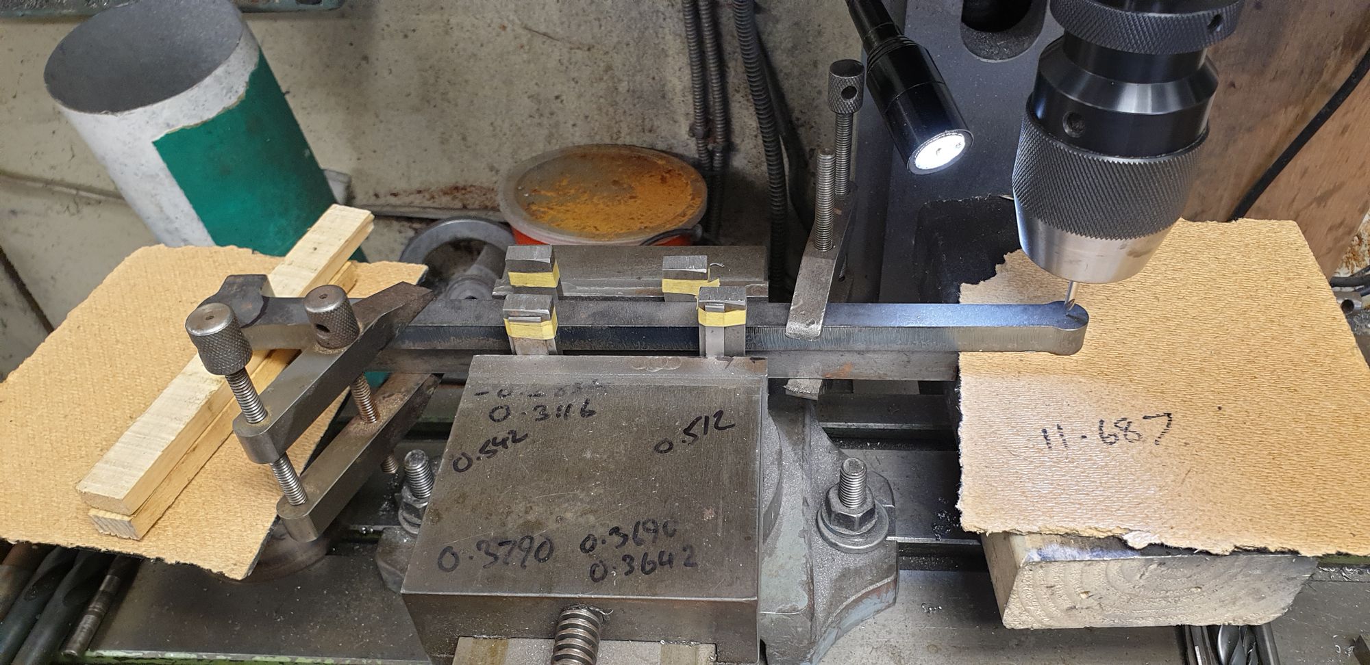
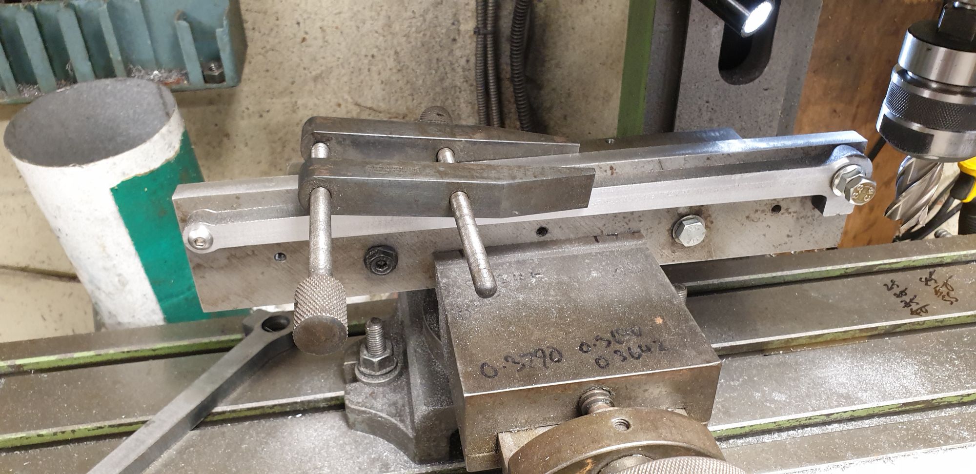
The first machining job was to drill both the little (9 mm) and big (0.656)end holes. This involved a little more set-up than with the coupling rods as the connecting rods are tapered. The picture hopefully shows my method in tackling this long tapered piece. I first selected a length of steel that was narrower than the rod and strong enough to support the rod during drilling. This length of steel was clamped to the rod using tool makers clamps. I then measured the width of the rod where it sits in the machine vice, by subtracting the difference and then halving the value I knew how much packing was needed to be used on the narrow end. I selected some chunky sections of steel of the same width and taped to them two sizes of steel used as shims to hold the rod parallel with 'X'. To finish I trammeled the rod using a small centre drill in the chuck to spot check that it lined up with the centre of each end. Once happy, I fully tightened the vice and zeroed on the big end and then using the DRO checked that both ends were central with the 11.687 CTS. As can be seen packing was placed under the drilling points
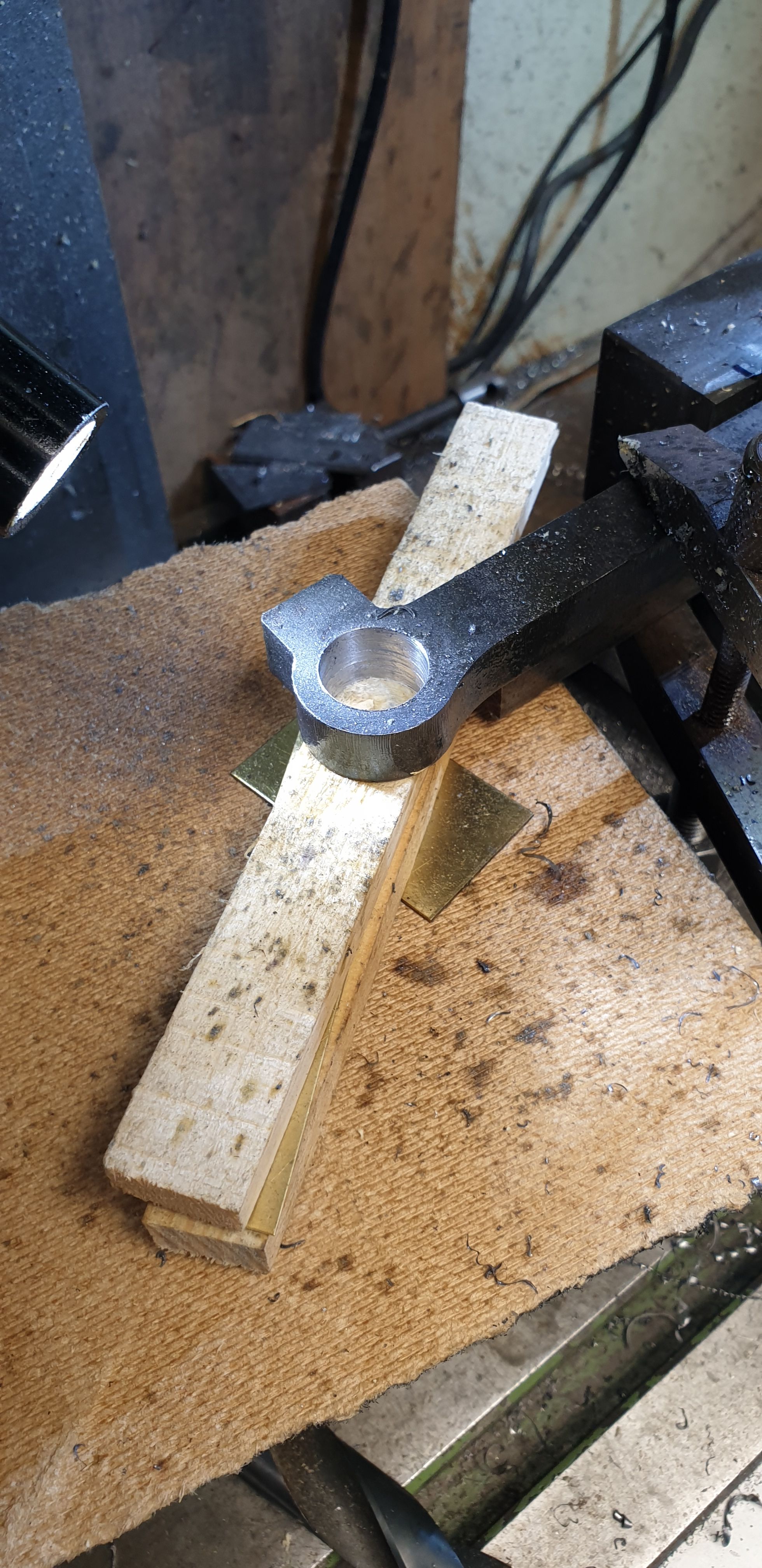
I stepped drilled the two holes using as many steps as possible, especially for the big end. Here's the little end drilled and reamed to 9 mm.
Next up was the big end, this was drilled to 0.656.
With the all important 11.687 CTS measured and holes drilled I could fit each rod in turn to the jig, this is a good chance of double checking that the holes are in their right place, if not, they wouldn't fit the jig. The first operation was to machine the laser cut blanks down to their correct thickness, well I couldn't do this as the blank was already undersize, no big deal, I can always increase the width of the 'brasses' if there's too much 'side ways' play. Instead of using the planned bolts spaced along the jig, for this stage I used a clamp as it made life much easier. Here I have just placed the clamp for show but for machining I would remove the bolt on the end that I start, (left hand) and place the clamp nearby, machine up to the clamp, replace the bolt, remove clamp and machine to the other end and repeat.
The next job was to machine the end bosses on the rotary table, alas i forgot to take a picture of this stage, it was an interesting stage with a foot overhang of metal. all went well though, I have left the bosses a few thou oversize for now, I'll finish them when all other operations have been completed.
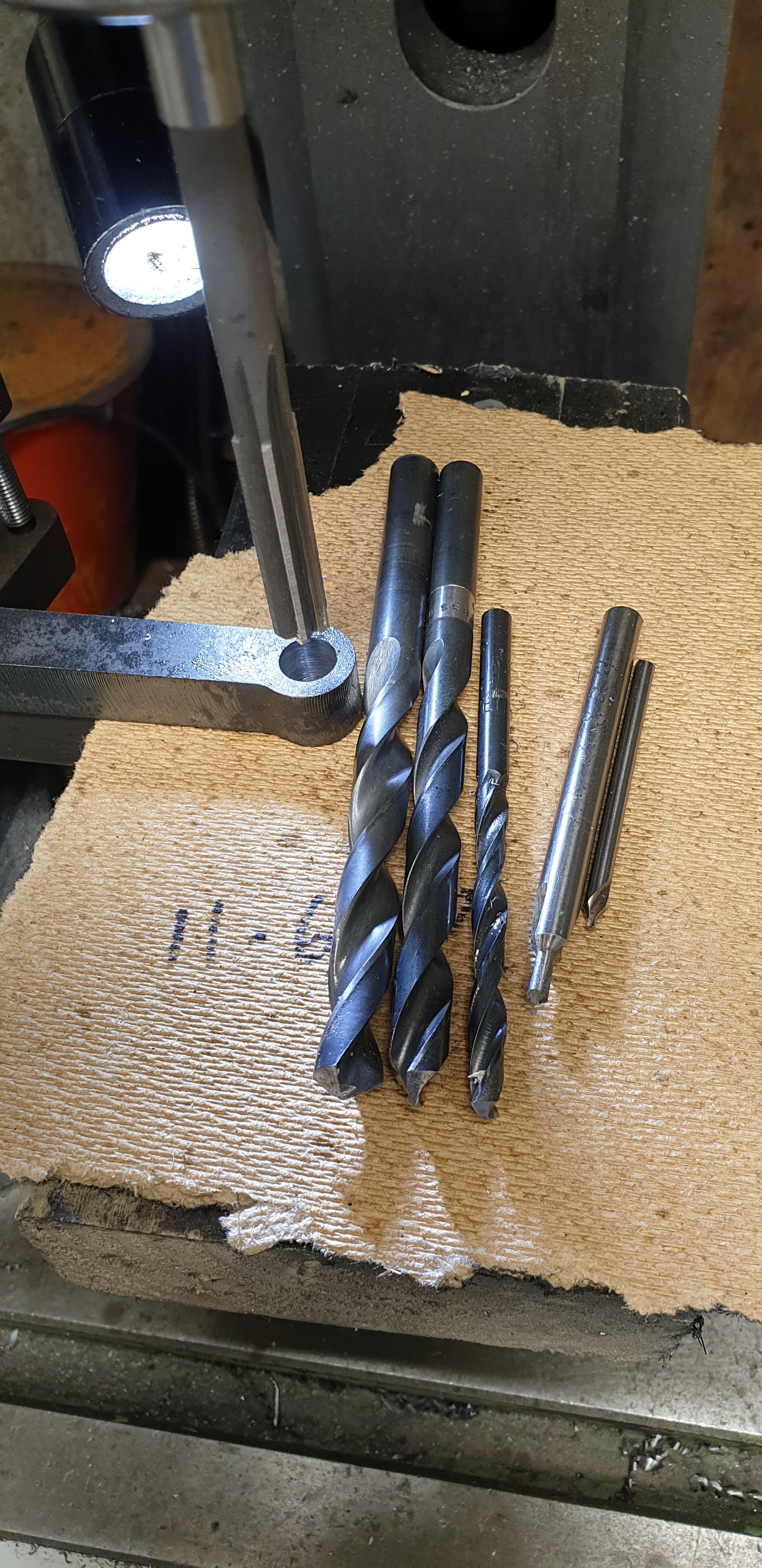
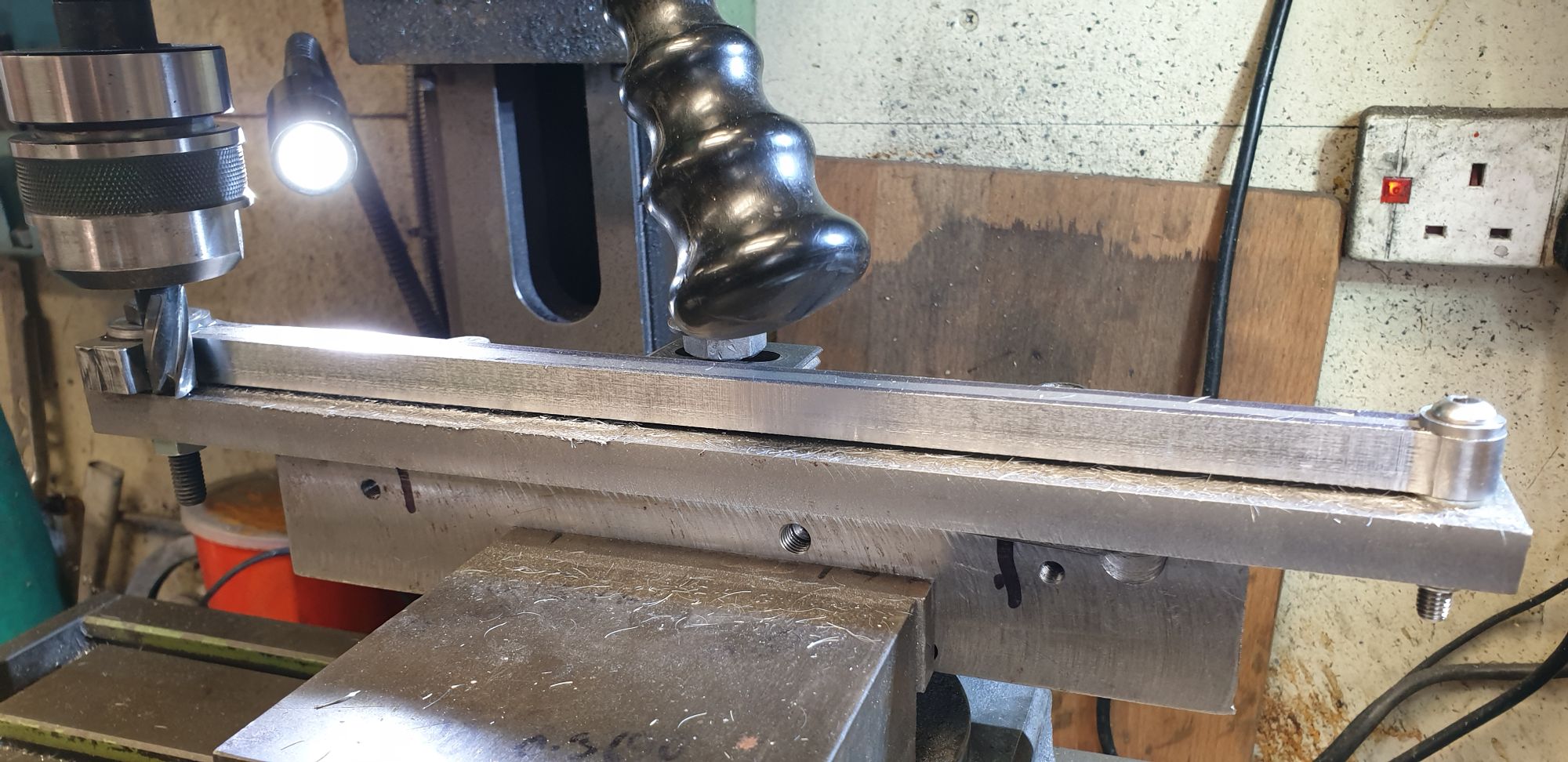
It was then time to machine the side taper, for this the jig is placed on its side and held central in the machine vice. This is pretty straight forward for me as I have a swivel vice which makes life a lot easier. This taper is very small, less than 1 degree and it was tough going breaking through the hardened metal due to laser cutting. In fact I struggled with this one for some hours using different cutters, I eventually dug through the cutters that my son gave me recently and found a couple of carbide cutters of the required rad. Well, this was like 'night and day', after struggling in the pitch black for hours the sun how now risen and I was cutting through this hardened metal like butter...lol I had originally set up the taper so that the cutter just kissed the metal along it's length, this wasn't quite right giving me a larger width at the little end than drawn. I adjusted the angle accordingly and achieved what was required, 0.375 width at the little end. Note that I have placed some washers under the rod to stop cutting into the jig, I should have done this before starting.
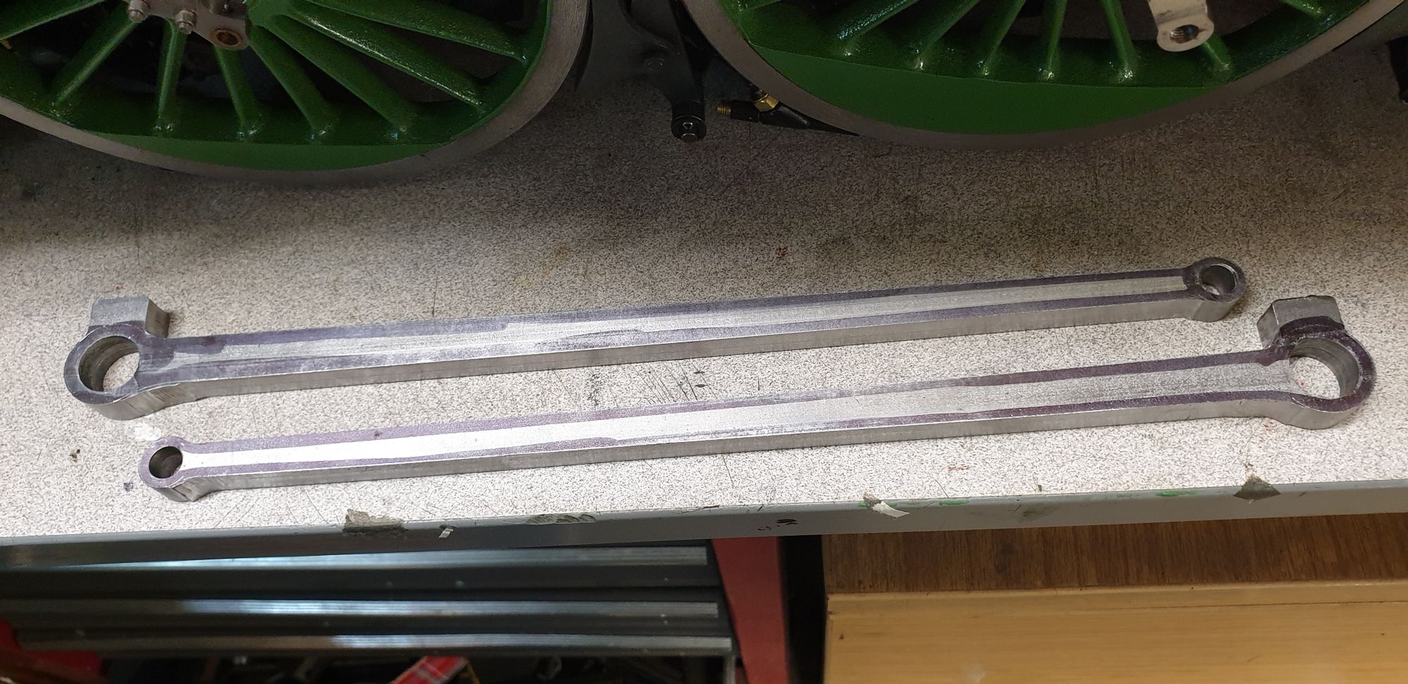
And here we have the two rods having now had their roughing out cuts completed. Happy to report that there is no sign of any warping/twisting of metal which is what I had hoped for with HRPO steel, mind you, at 12 inches long you just never know.
Next update should see these rods completed, first I'll blend in the taper lengths to the bosses. Machine the oil reservoirs to size, drill and tap and then on to removing all that metal from the middle and finally the tapered flute. Sometimes I think that I should have chosen a prototype with plain rods with no fluting, not to mention the fish bellied coupling rods with fluting to match.. I must be mad... think I've said that before?..:)