
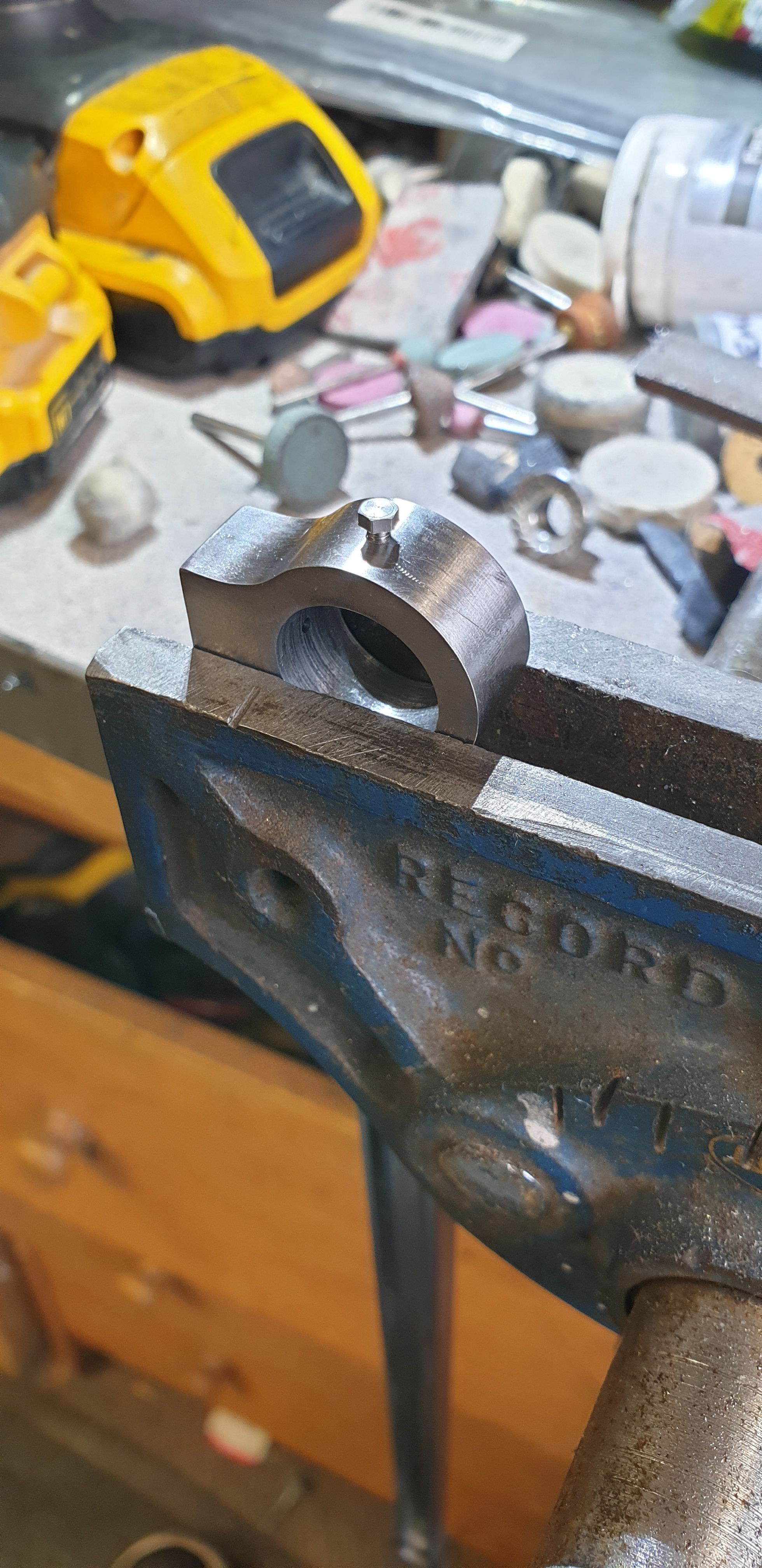
Next up was to machine the oil reservoirs to size, this is the last operation with the jig this way up. The carbide cutter once again made little work of cutting through the hardened metal. DRO readings were noted to ensure that both rods were identical. The picture shows the first rod to be machined, once both were to this stage I then finished profiling the bosses and oil reservoirs with the Dremel using two sizes of sanding drums. I didn't take a picture of that but you can see the results in the upcoming pictures pictures.
The jig was then stood up for the remaining operations left, the first of which was to reduce the central section down to size, here we can see the first rod with one side completed. Once this was done, I again noted the DRO readings and repeated for the other three sides. When machining the second side, suitable packing was used to ensure the rod didn't deflect during machining.
It was now time to tackle that lovely job (not) the fluting. The custom woodruff cutter that was profiled for me to do the coupling rods lost its edge during the final cuts on said rods. I have tried to use an oil stone to achieve some sort of edge but it wasn't sharp enough for the job in hand, that is, to cut into each rod on both its cutting edge and side rads. I have there fore approached the connecting rods differently by first roughing out the center of the flute with a new suitably sized woodruff cutter to remove most of the middle section before attempting the side rads. I have followed what I did with the coupling rods, that is to machine a flute into both sides. The front face being machined close to the correct depth and the back shallower. For the connecting rods, I have machined to the same depth as the coupling rods on the front but for the back I have only machined to a 3rd of the front. Don in his words said of the coupling rods that if you want to impress the judges machine a shallow flute on the back ( no that is not why I added the flute, I'm not a fan of fluteless rods when the prototype has flutes, even if just on the back) , however for the connecting rods he has said to machine a flute to the front only. These rods are very long (12 inches) and thus if too thin risk damage from the pounding that they are subject too. Ok, so to achieve the right look and also keep the required strength I have compensated a little. The center section has been left oversize by 5 thou, the front depth flute (as with the coupling rods) is undersize by approx 8 thou (85 instead of 93 thou), the reverse is only a third of the front.
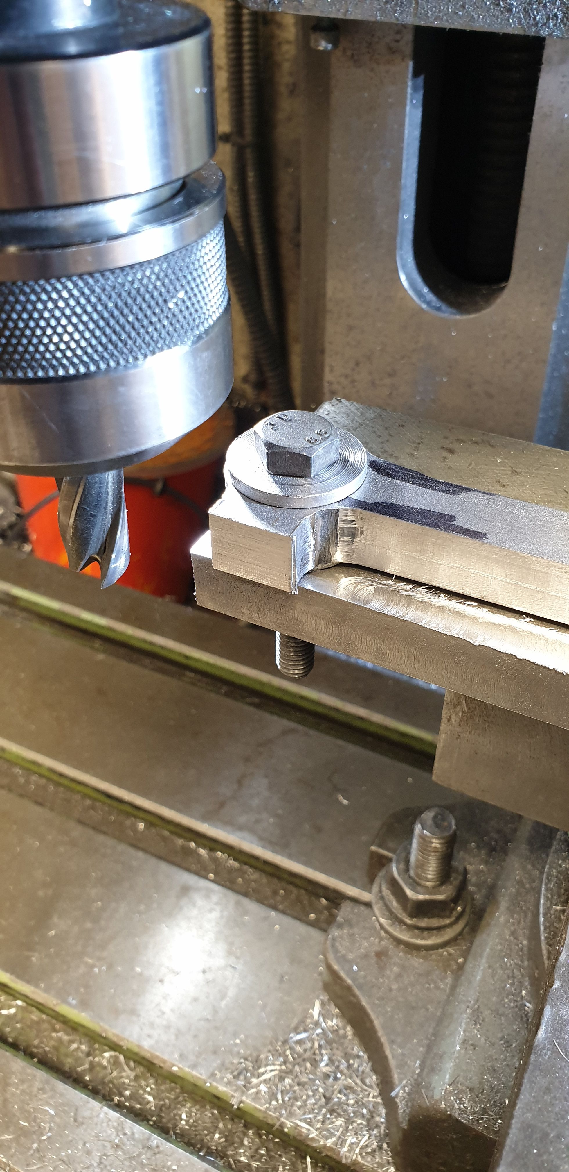
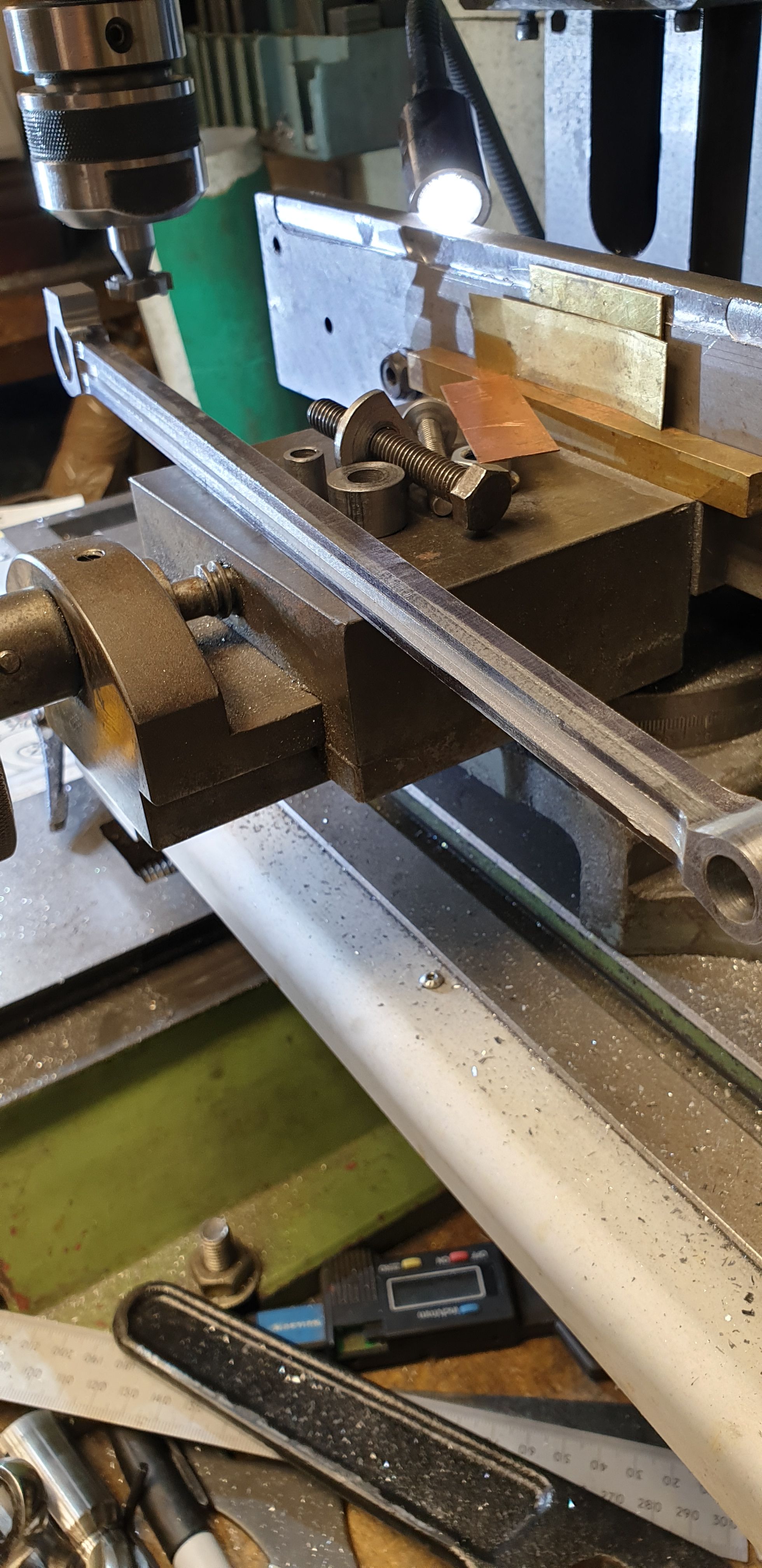
So I think that these steps should at least match the original strength if not be slightly stronger due to the wider center section. The picture below shows the roughing out of the middle on the back of the R/H connecting rod. BTW, I only eyeballed the center as it's not important, the flute will be centralised when cutting the taper.
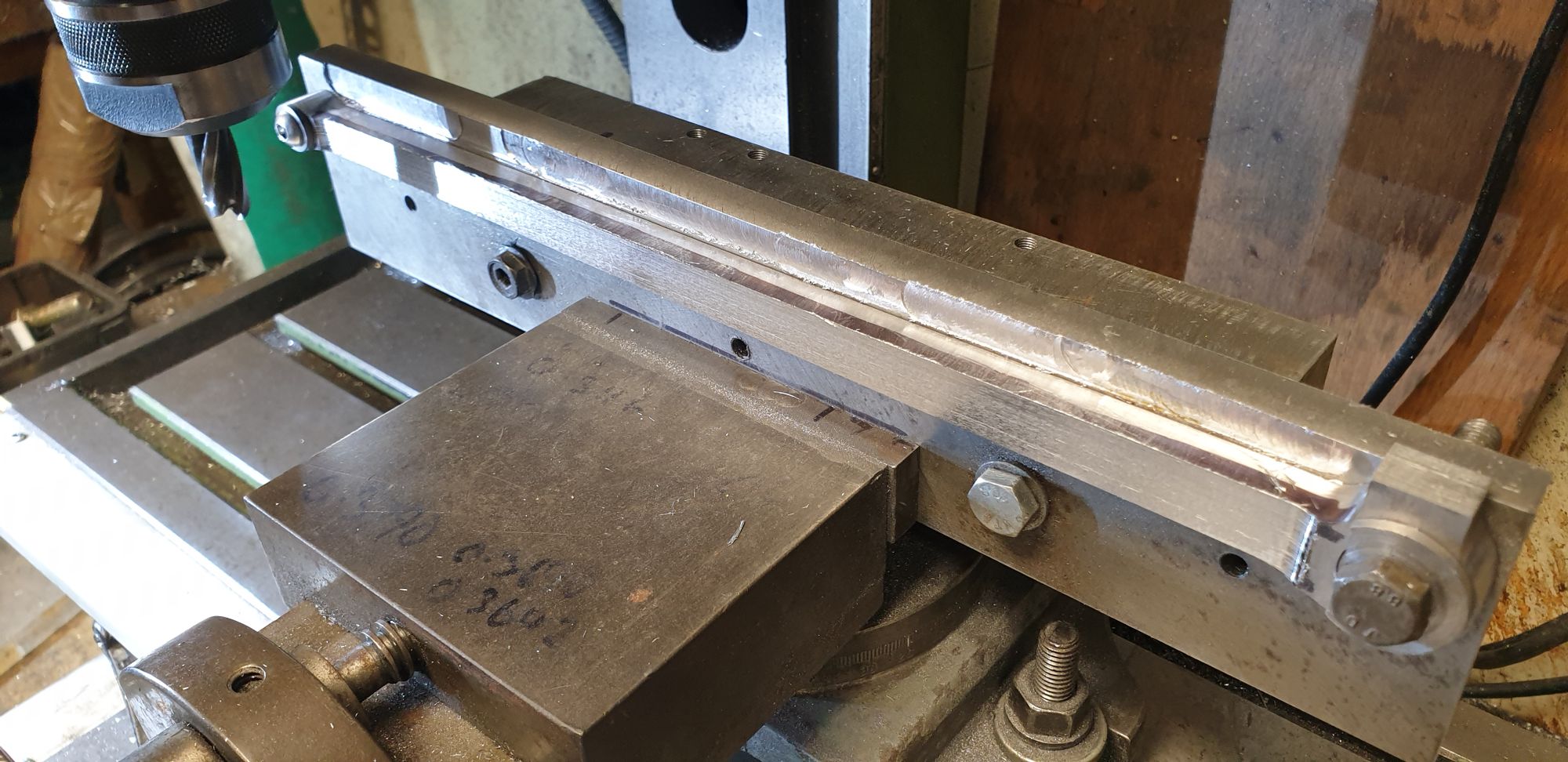
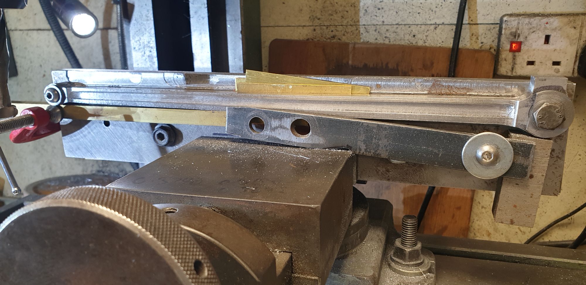
Here's the front of the same rod, I have tried to take this at an angle to best show the depth of the fluting.
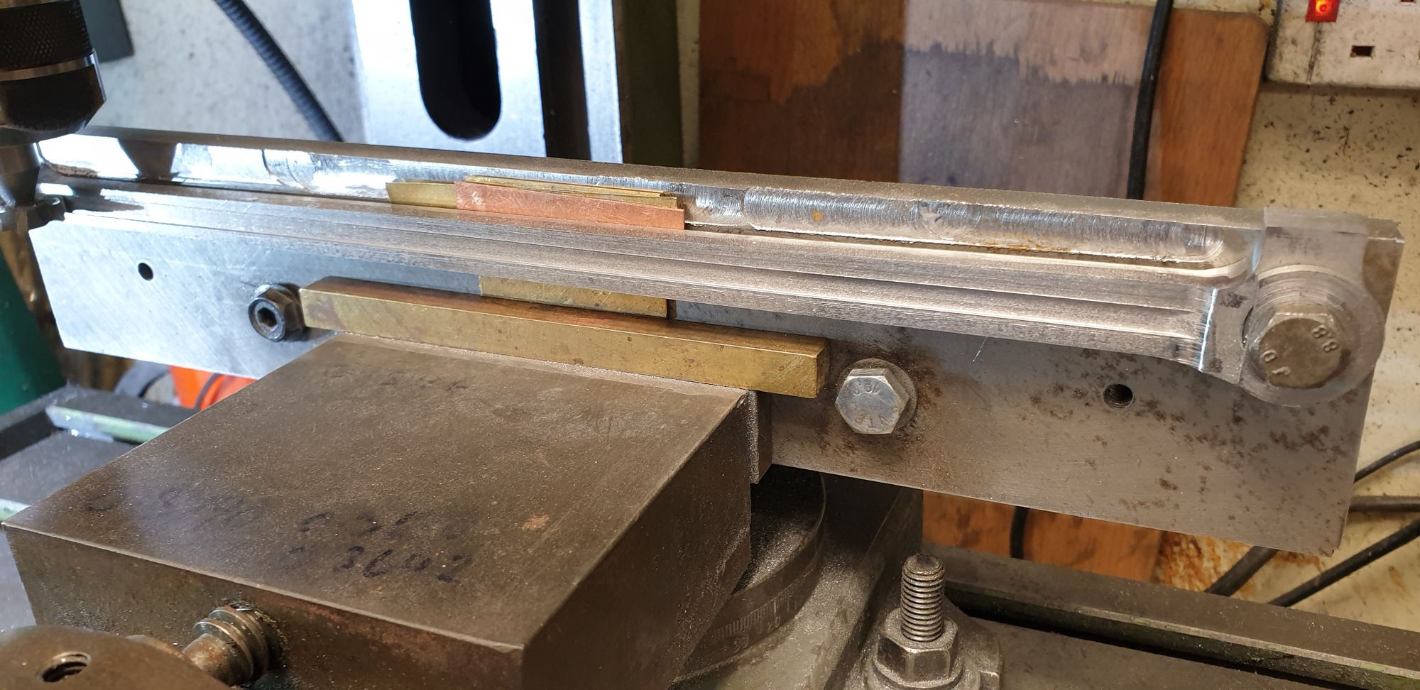
Next job was to machine the taper edges of the flute, this picture shows the top edge after machining. I forgot to take a picture of the setup so will describe it. To get the correct angle I used my trusty digital angle gauge which has been seen in these pages a number of times now, it's a handy little gadget. Simple to set up, I first zeroed the gauge while sitting on the machine vice> I then placed the gauge on the top edge of the rod, noted the reading (in this case 0.3 degrees) and then sat it on top of the jig. I then found a piece of brass shim, loosened the vice and lifted the jig at the correct end until the gauge gave me the 0.3 degree reading. The shim was pushed under the jig on the raised end, checked that the jig was sitting on it and still reading 0.3 degrees and tightened securely. Final check was to place the gauge back on the rod to make sure it was now at zero. Once both rods have been so machined on both sides I'll finish the fluting by hand blending them into the end bosses.
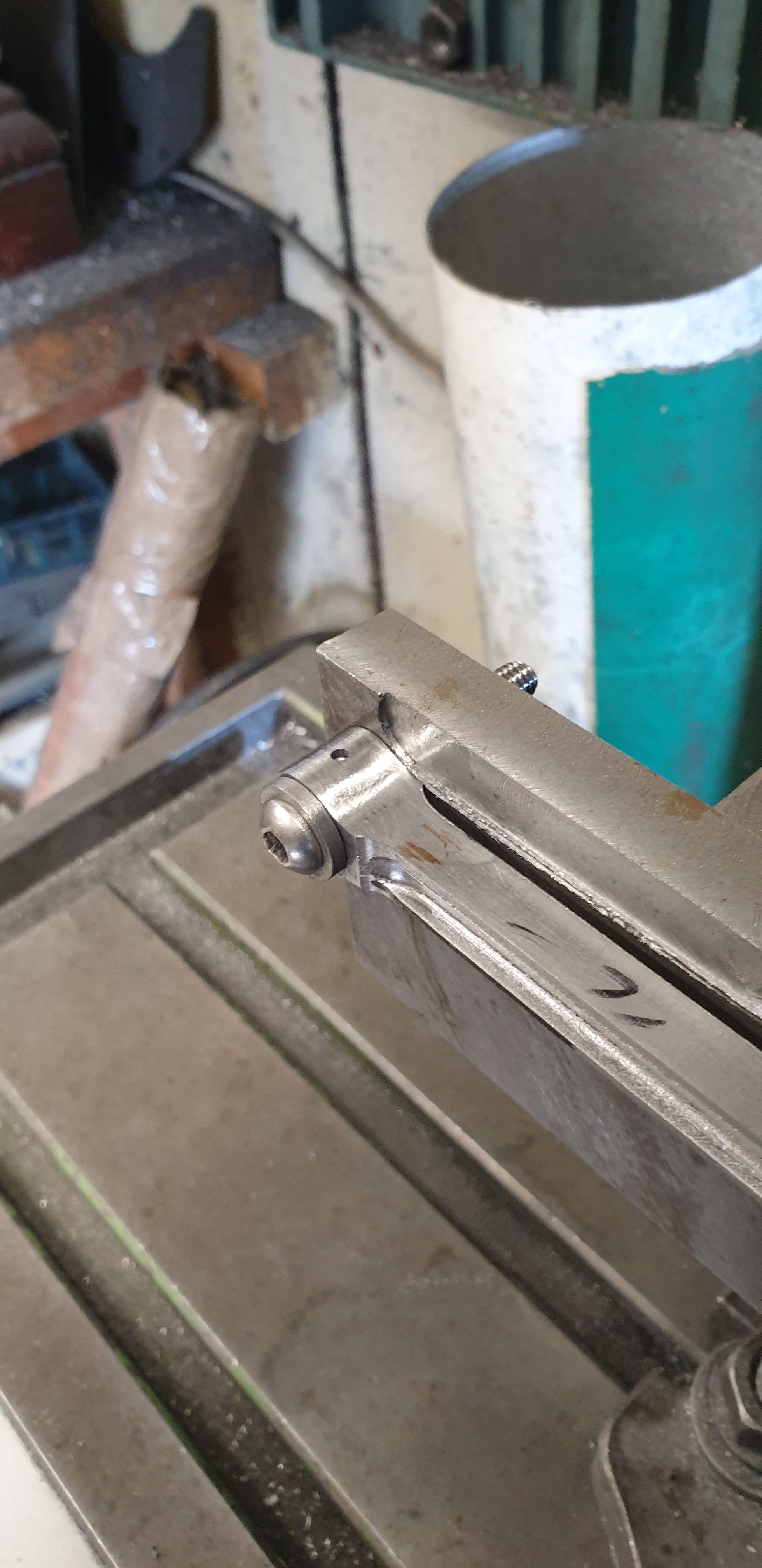
With the flutes roughed out and before removing the rod from the jig I drilled the two oil holes in the top of the oil reservoir and also a hole in the top of the little end. I have drilled this hole as a backup oiling system to the oil feed system already described.
Here is the little end...
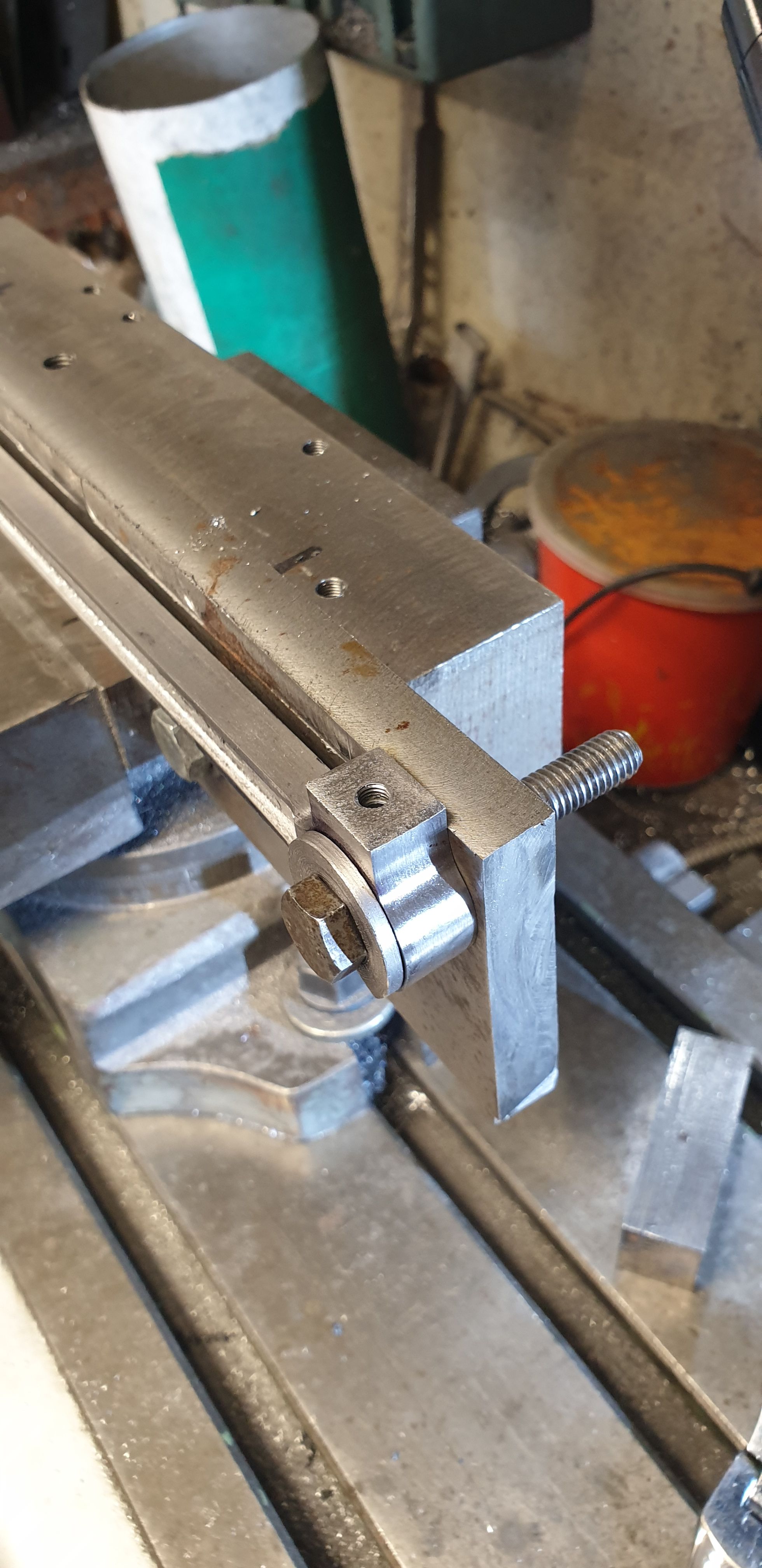
and the big end with it's 3/16 x 40 TPI hole for the cap/plug to screw into. I'll make the caps later from stainless steel to match the steel caps on the prototype.
Next up was the drilled/tapped 8BA hole in the middle of the big end, due to the length of the rods I found this best to be done by hand after first marking out it's position.

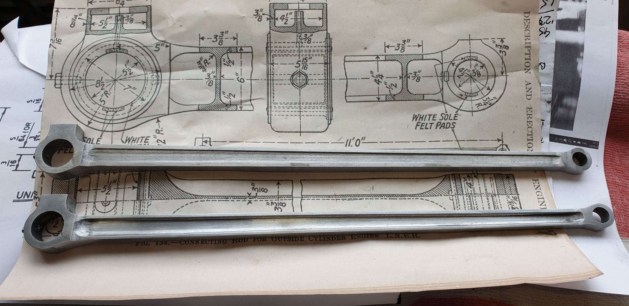
we are nearly there now, a few more polishing sessions and a little added detail but this picture shows generally how the rods are. The rod closest to camera is what we call in the film industry the 'hero' rod, what I mean by that is that this is the R/H rod as it will be seen on the model. The other rod at the top is the L/H rod as seen from behind, that is the inner face of the rod. The fluting of inner faces of both rods are machined to a third of the front face to keep strength in the part. Don notes on his drawing to not machine the reverse face, I don't like leaving flat faces on the motion as some can be seen from behind, so the fluting here is just to give a sense of the shape to please keen eyes. I will go over the fronts one more time to tidy them up more once I have some new brass wire wheels, those lovely things that cover you in debris..:) The drawing seen here is a full size section and writing these notes now tells me that i still need to flatted off the top of the little end, I'll do that next before I forget..:)
A fellow model engineer (Norm Norton ( current Brit articles in ME mag)) posted pictures of his Brit showing number stamps on his connecting rods. I had noted these numbers on FS and in fact took some close up pictures of them back in 2016 but didn't realise that number stamps were available in such a small size, thanks' to Norm I was soon ordering a set of both numbers and letters of said stamps.
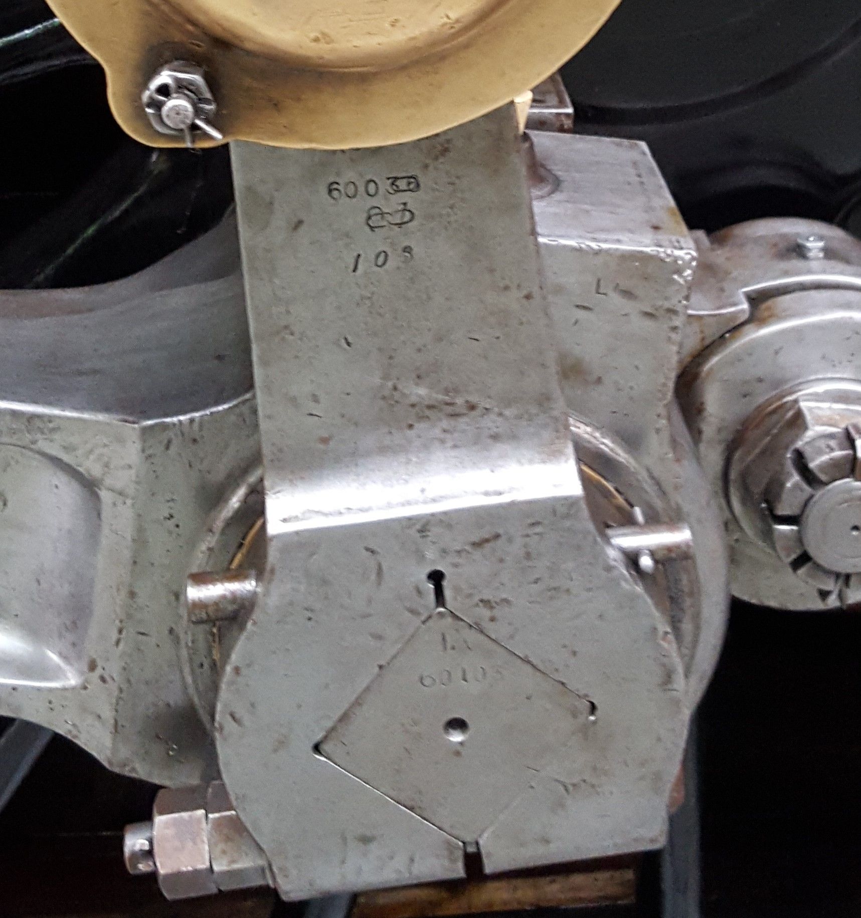
On FS today there are many numbers stamped on motion parts, in fact some look a bit of a mess but i thought that now armed with a suitable set of stamps that i would follow Norm's lead and stamp my own. First a couple of pictures of FS that I took at York in 2016, this one is of the return crank, note that according to the previous number that's been partly stamped over, this return crank came originally from 60036 Columbo. You can also see a single 'L' on the connecting rod to show which side it belongs. I assume the number is hidden by the return crank.
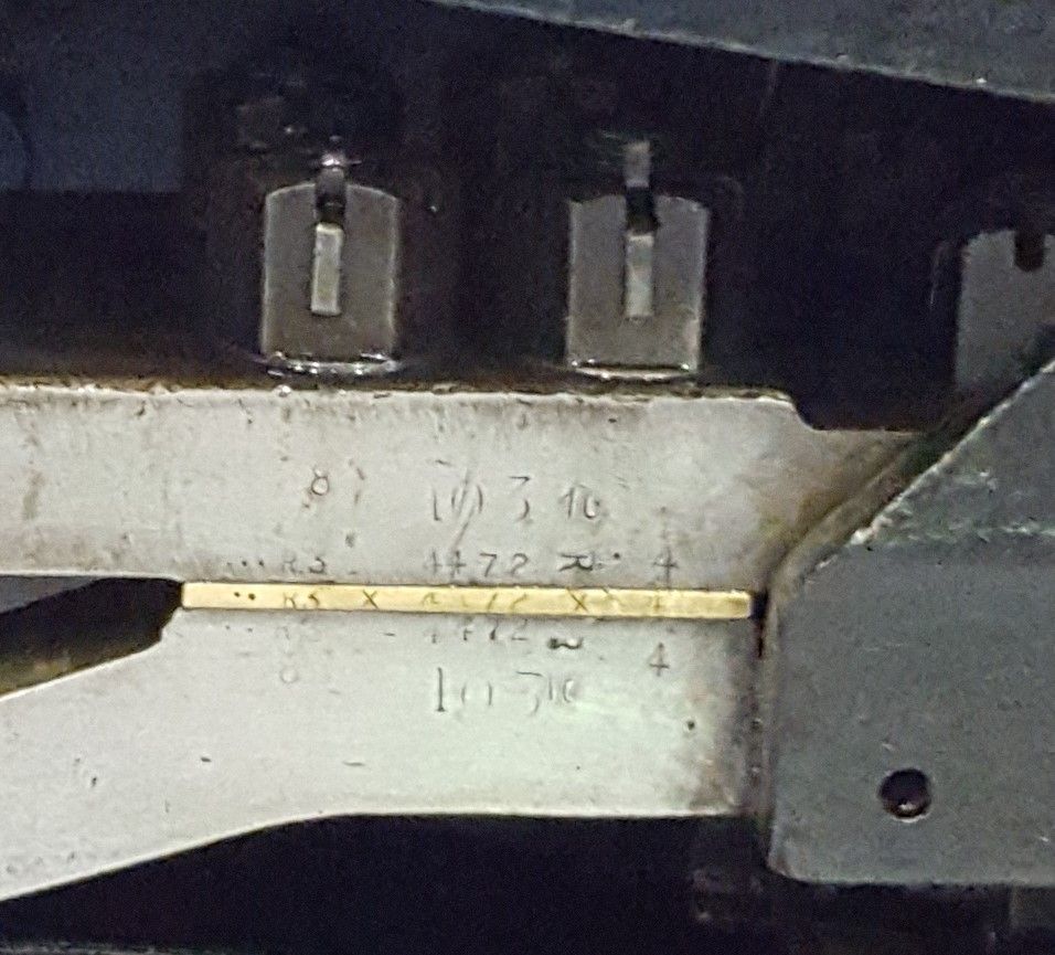
According to the Haynes FS manual which shows a number of photo's of the numbers stamped on various parts, there is rumor of one of the slide bars still having the stamp of 1472 and thus original. Again, I took this picture at York, a bit of a mess with numbers everywhere (some of which I don't know their meaning) but it's clear that the slide bars are stamped along with I believe all motion parts. In this photo you can see that even the brass shim is stamped, 4472 clearly seen on both upper and lower slide bars along with the brass shim, you can also see where 103 has been added representing BR 60103, plus the sideways 'R' to show which side they belong too. I will take a look at adding these to the model during the motion's final assembly.
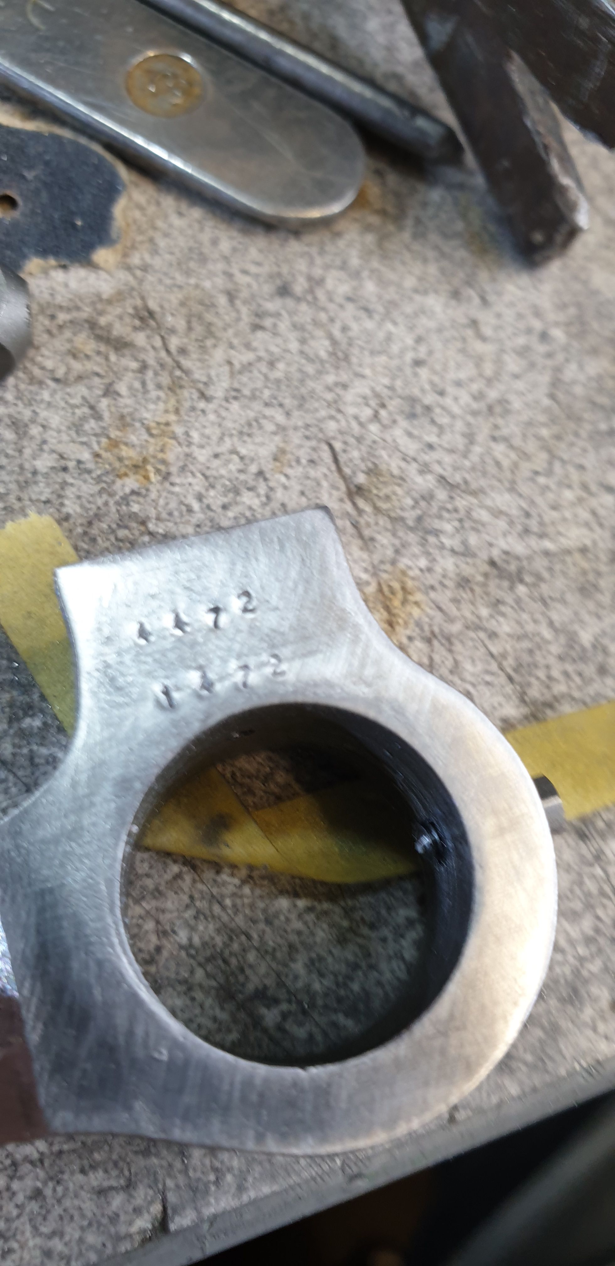
Back to the model itself, this close up is cruel as all close views of metal are but I have stamped both rods and to add a little interest (provenance) on one side I have also included '1472', after all, in 1938 I would expect there to be a number of original motion parts still in use, I know of no records that gives these details so will take pot luck at adding the detail here and there. I haven't been as disorganised as full size but haven't been too worried about getting the numbers lined up regimentally. I also hadn't spotted the 'L' mentioned above before taking this picture and so will add both 'L' and 'R' to the relative connecting rods later.
Next job (jobs) will be to machine the 'brasses' and fit the rods along with their crossheads and pistons.