
As pointed out during the crosshead construction, the drop link design varied during 4472's career. My goal here is to try and make something that looks like the drop link in the late 30's but while also following the 'Doncaster' dimensions for obvious reasons. This goal is further hampered by the fact that I don't have a drawing for 4472's drop link and the photo's that I have found aren't that clear, especially when trying to view the rear side with it's oil reservoir.
I have built the crosshead and drop link with the best info that I have to hand, if a part of either is wrong, no I'm not likely to change it, he says...:)
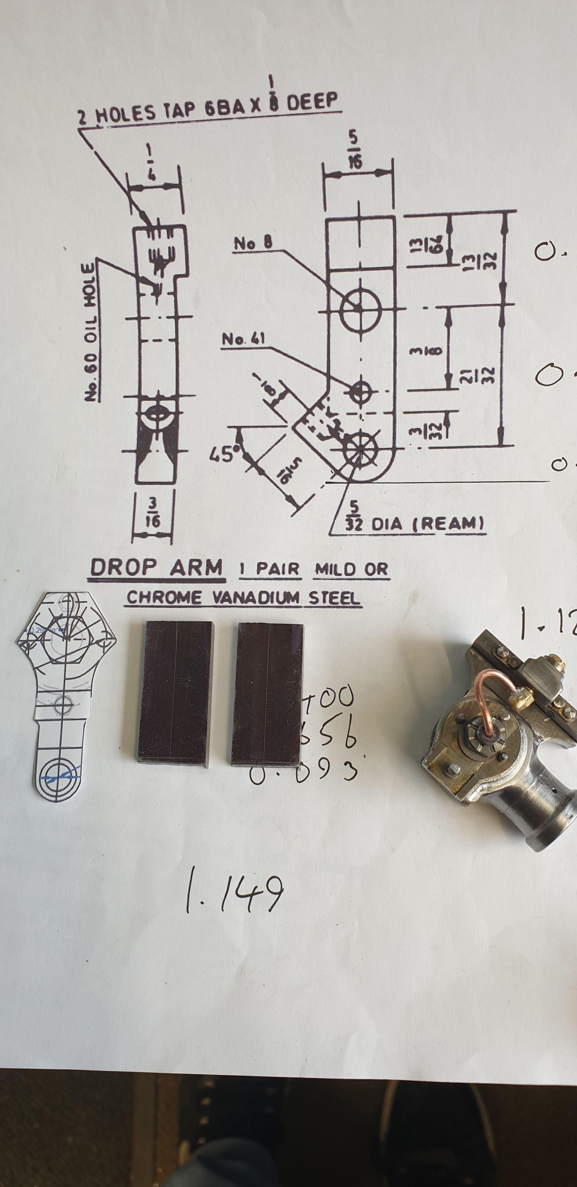
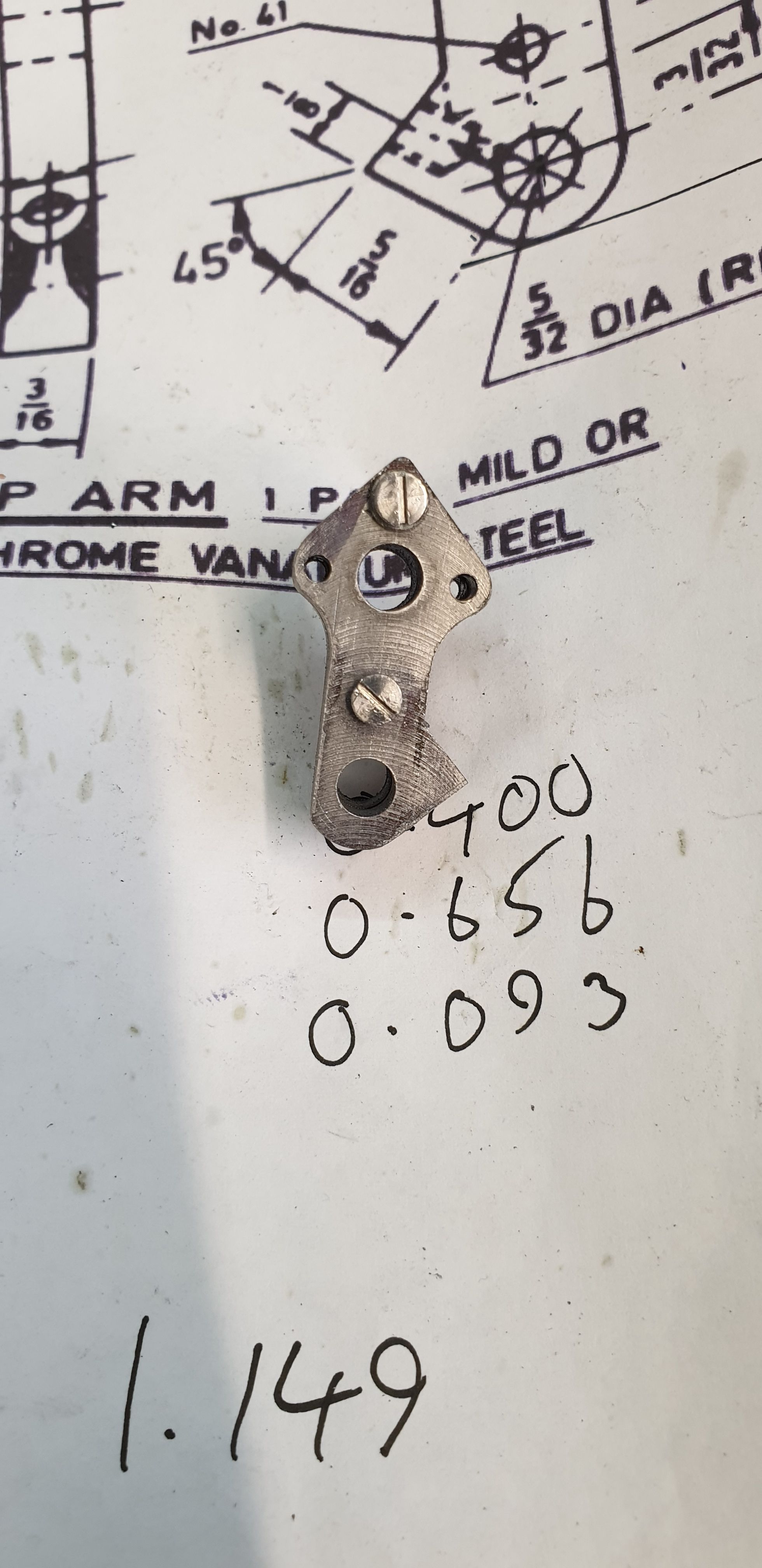
To begin with I've taken this picture of the 'Doncaster' drawing, along with a cut out of the 1934 pattern, both are enlarged. Now the cutout drawing isn't exactly the same as 4472's, the upper part is similar but 4472's has a triangular plate. The lower end is drawn for Eddie's K3 or H4 loco's which are designed for different jobs and thus have different cut-offs. among other aspects the different cut-offs result in different length drop links. Both the K3 and H4 having longer drop links than 4472 and so I have to work the drawing to suite. An added consideration is the oil reservoir which isn't yet shown ( Eddie hasn't drawn it yet) on the 1934 drawing. I'll go into more detail as I work through the construction. The other thing to point out here is the two blanks seen which have been machined down to 3/16 thick ( well actually, 5 thou under to allow both clearance of the union link fork and for me to fit brasses which are not part of Don's 'Doncaster' design. There is a centre line scribed on them but it's not central to the blank as I need it offset a little to be able to fit in the oil reservoir. Regarding the intended 'brasses', to allow for this I have enlarged the 5/32 shown on the 'Doncaster' drawing to 3/16 reamed, this will also be explained more later. BTW, material used is gauge plate.
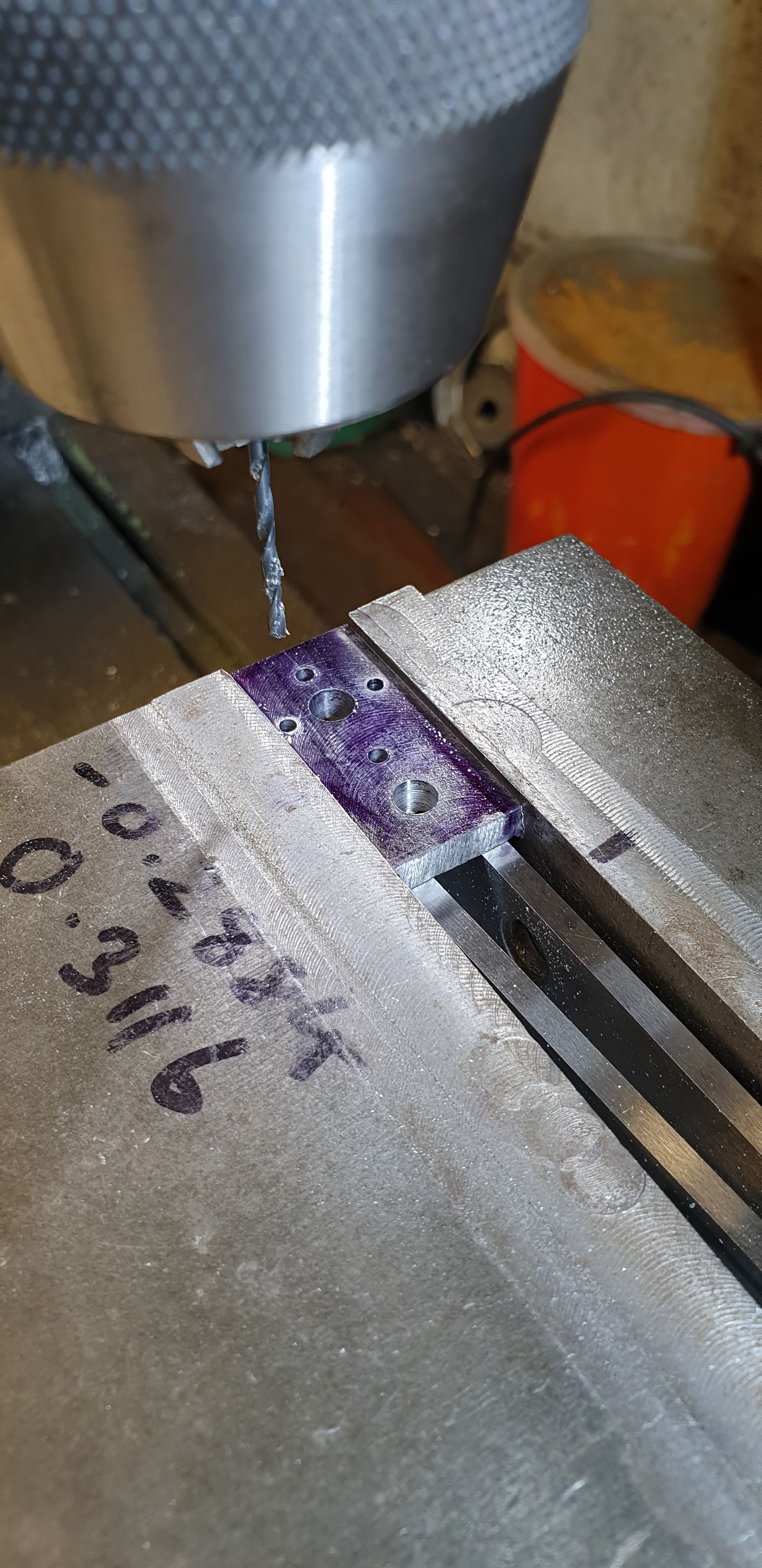
Using the drawn line as my datum, I plotted and drilled all of the holes to match those on the crosshead and mounting plates. Whereas I earlier drilled the mounting plates together, for these I have drilled them separately as they are much thicker and I didn't want the small drills to wonder.
Once both blanks had been drilled I bolted the two together and began to profile the lower section. To get the parts to both fit and look like they are how they should be I have changed a few dimensions, I have used a smaller arc for where the bottom leg meets the upper section. This was done so as to allow the required parallel section to fit between the mounting plate lugs and also to avoid cutting into where the oil reservoir needs to be. it was a bit of a joggling act but I think that I found a happy compromise.
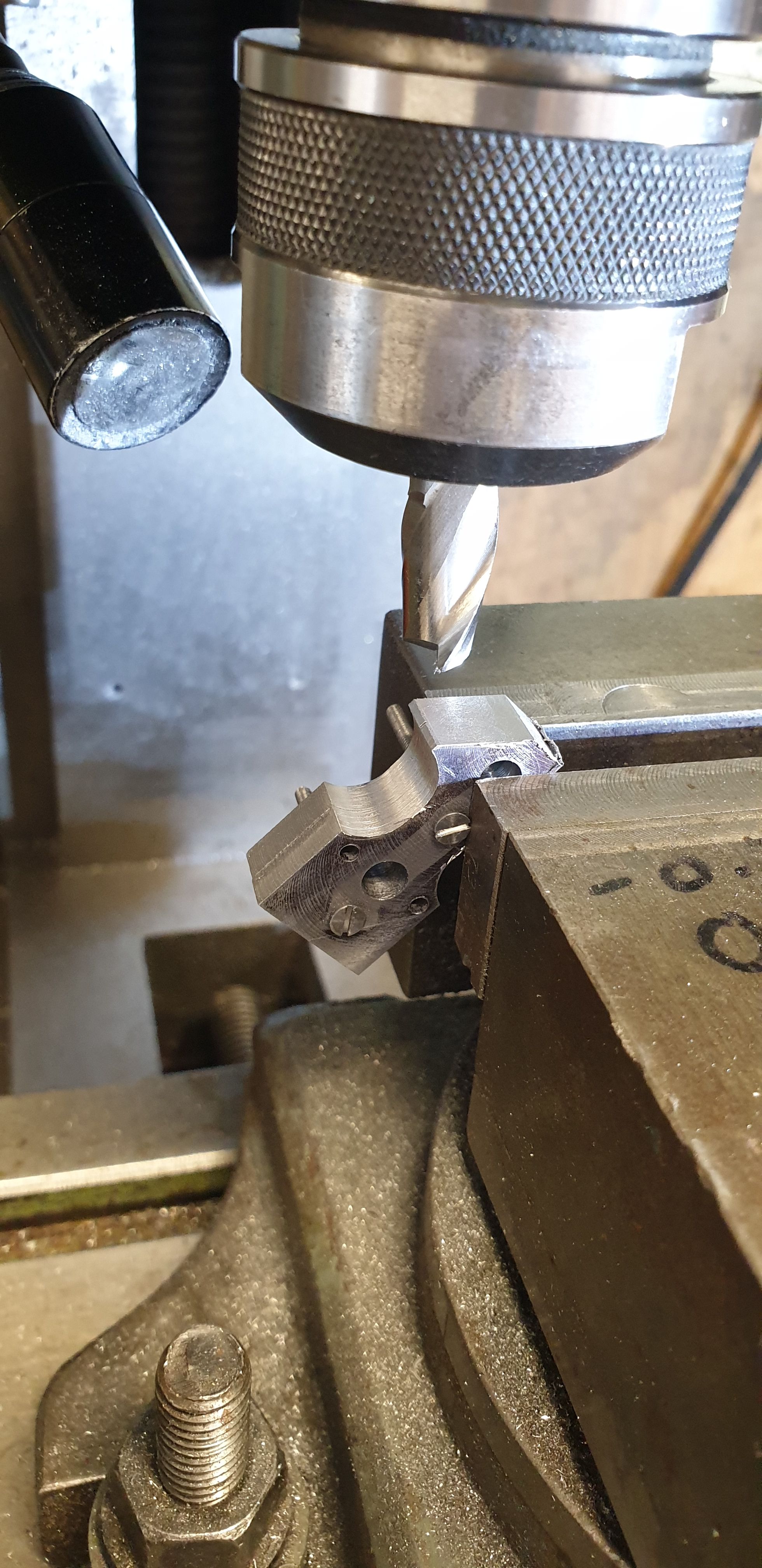
With all of the 'square' machining completed I then moved on to the various angles, I began with the angled rear face of the oil reservoir. Alas I forgot to take a picture of the return cut for the top of the reservoir. This was done using a smaller cutter which I machined to a marked line for the parallel upright section which fits between the lugs. To finish, the drop link was held so that I could complete where the oil reservoir meets the upright leg of the drop link.
I then turned my attention to the upper angles, from the pictures that I have this area is also a little different to the cut out seen above, whereas that has a flat top, 4472 has a point with rounded corners, I'll show a close up of 4472 from that era shortly.
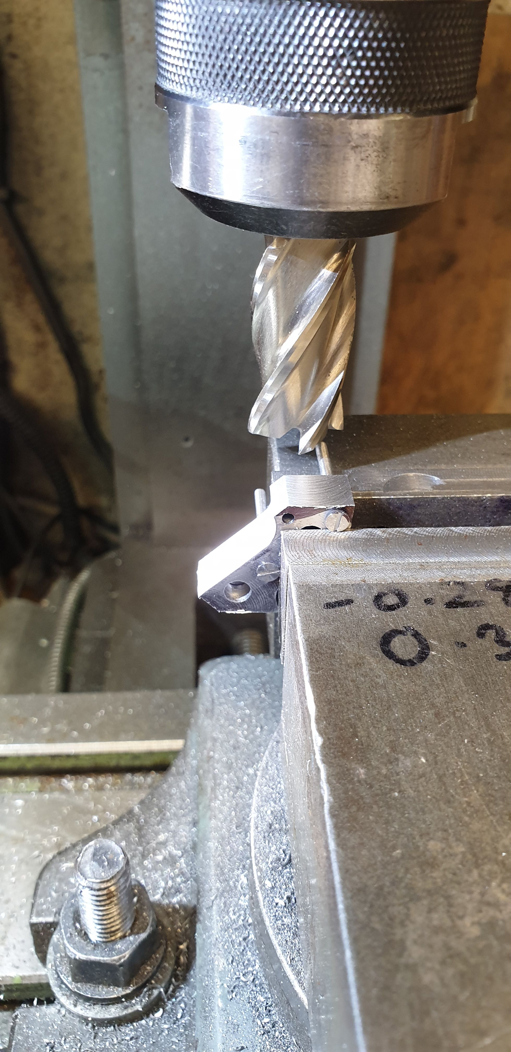
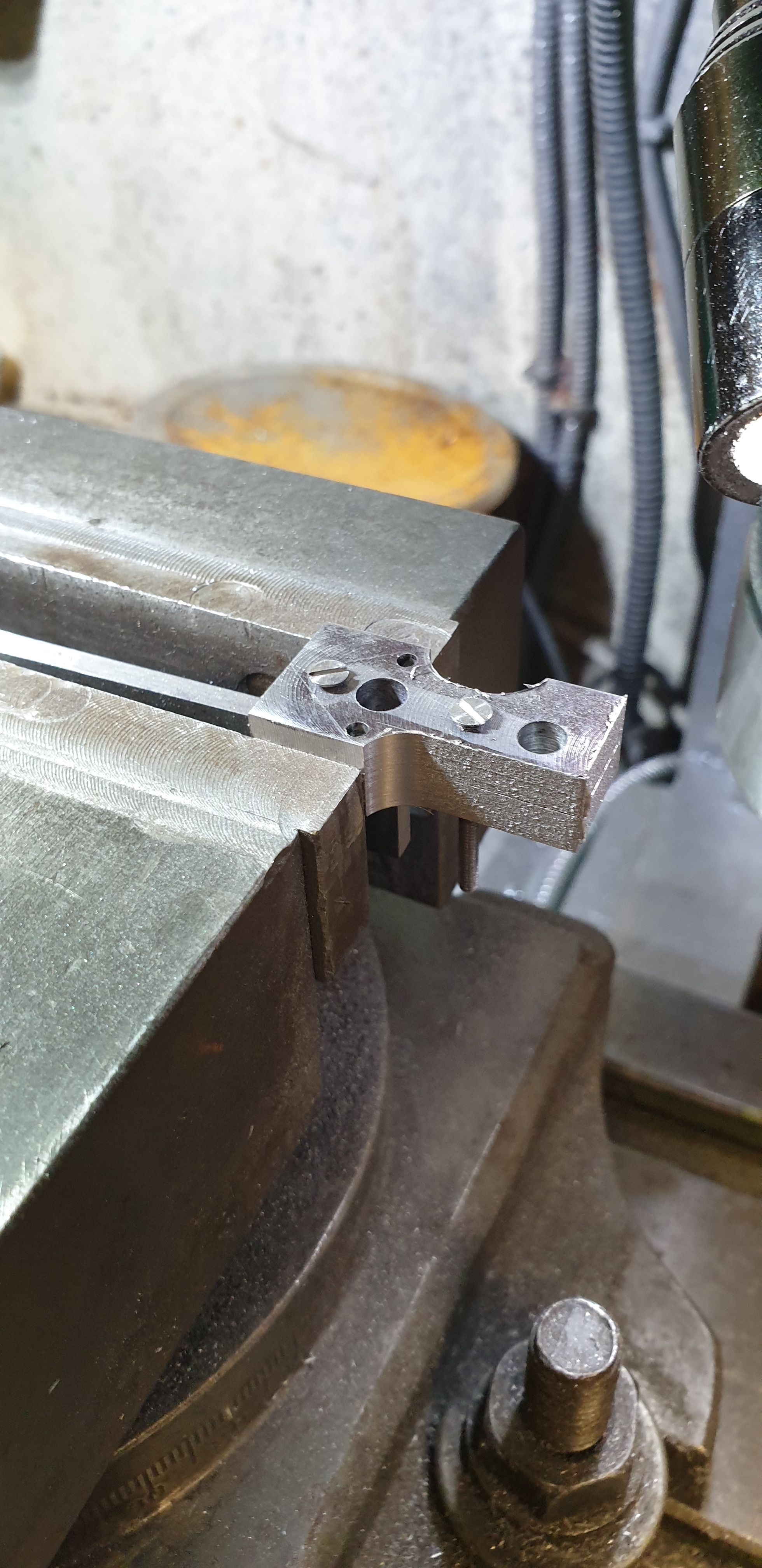
It was then time to return to the rotary table to round off the various ends, this picture shows the drop link with the machining of the profile done, the rest will be done by hand.
Before the elbow grease begins I first needed to machine the two steps into the front face, again this is different to the cutout but can clearly be seen in the photo's even if they aren't that clear. with the steps machined I dry fitted each drop link to it's crosshead. I'm happy to say that they both fit very well and are very tight even without the securing nuts. I will hand file the profile now to blend it all in.
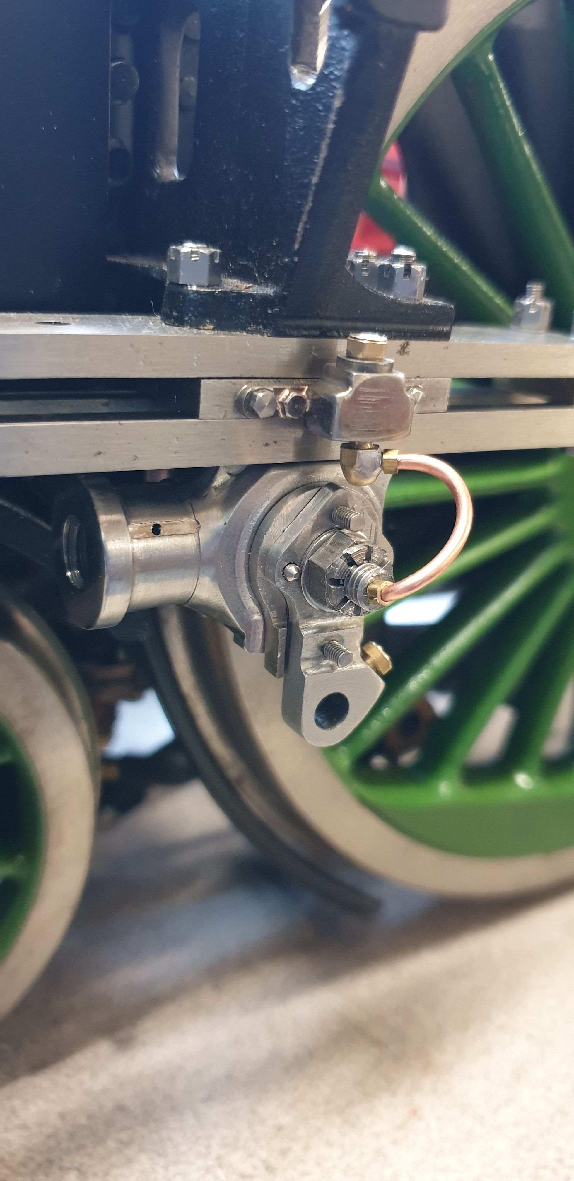
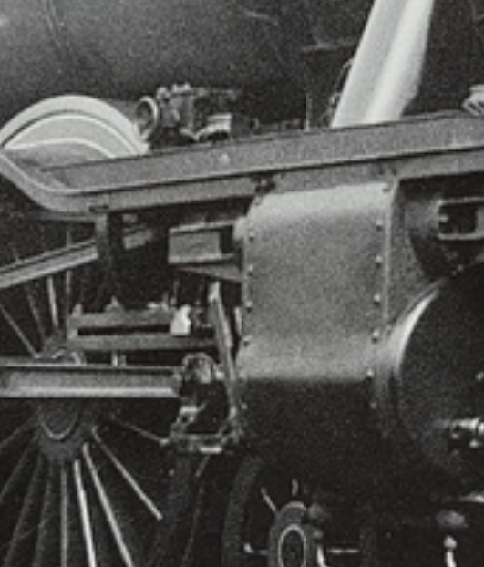
I think that this is the best image that I have of 4472 showing the drop link, this image is from 1936, another from 1938 shows the same part but it's not as clear as this one. Hopefully you can see the machined steps to the front face which I am trying to emulate. I still need to shape the lugs to match what's seen here.
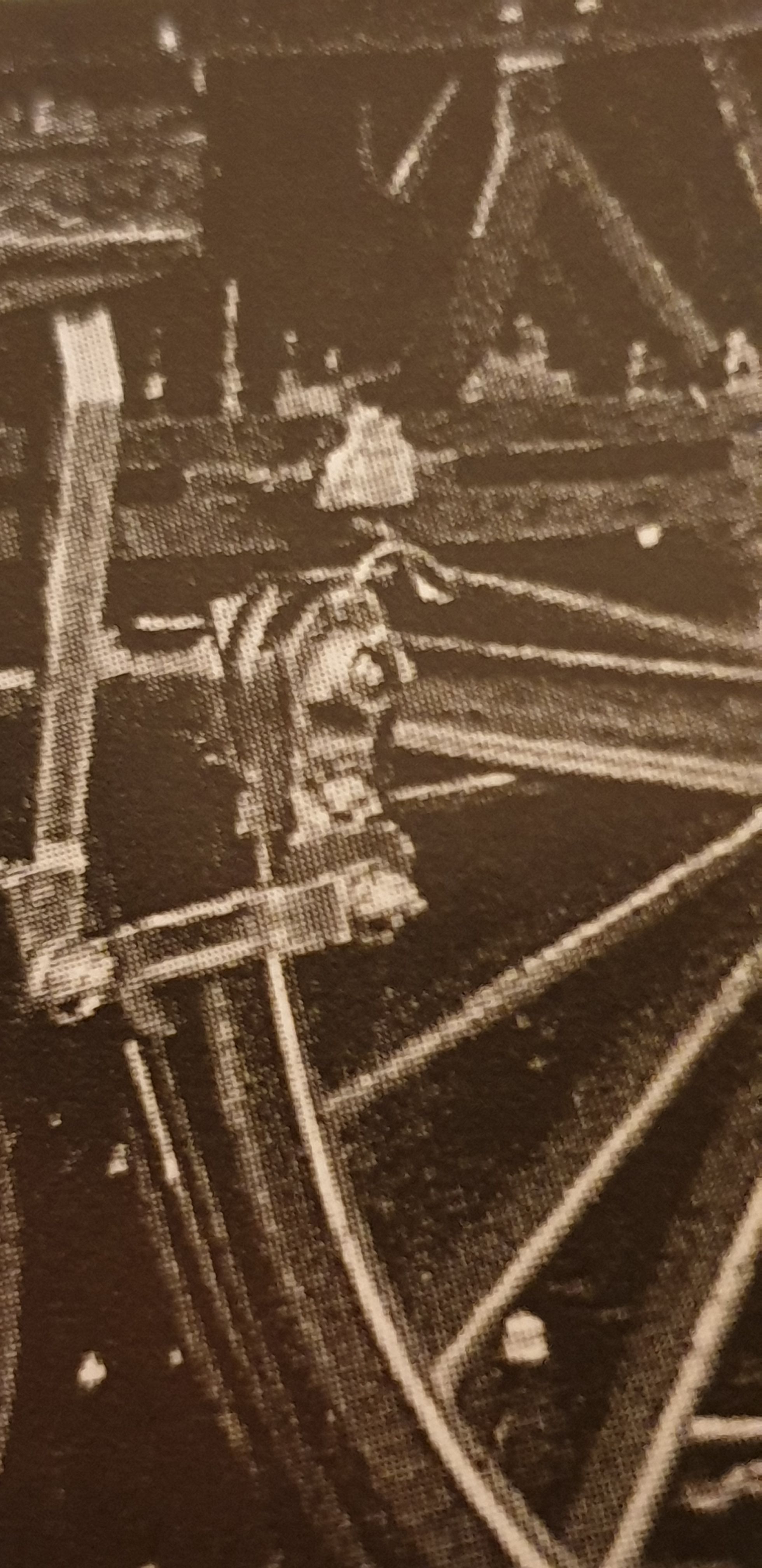
Now this picture isn't of 4472, it's another Pacific from late 30's. I have shown this as it's the closest that I have found to the last photo which I took of the model today. Note that this Drop link although identical in the lower half has the other type of upper shape with the flat top. When comparing this and the image above you can see the difference between the two. This Image is from the new book 'Gresley A1 and A3 Pacifics' 2020 by John Jennison, his copyright. If you compare this to the last image of the model you'll note how I have increased the pipe size to allow it to be functional.
One of the last jobs to do for the crosshead was cross-drilling of the gudgeon pin journals, shown in this picture.
Ok, so the finished(?) crossheads with their drop links fitted, they are only temporary fitted for now as I'll be removing the gudgeon pin a few times while fitting the piston rods and connecting rods later. I have shown the reverse side of the middle cylinder crosshead to try and show the CSK end, it's a little dark but hopefully you can see. I may shorten the gudgeon pin later to match closer to full size. Note also that I have drilled the oil reservoir for the union link pin and fitted an 8 BA brass plug with small hole to avoid an air lock as described earlier for the larger reservoir fitted to the slipper above. I haven't made the 'brasses' yet as I'll wait until I have decided on the size of the pin, I suspect it will be 5BA as that should give enough meat to the brasses (material will be bronze PB102) plus strong enough but will wait until I have the material to make the pins.
To complete these ( numerous) entries on the crosshead/drop link I'll show two final pictures of the model, this time I have included a picture from the rear quarter. The gaps between the mounting plate and drop link are purely due to them not being bolted together yet.
And the last image from the usual front quarter, it's only the usual view as this is the side which is currently accessible without me needing to lift the loco and turn around. A couple of things to point out, the top bolt is very close to the gudgeon pin castellated nut, think it clears the flat but I think that it may be prudent to make a slightly smaller nut here . You can also see one of the the dowels just poking through the drop link. Lastly I have cut up some small lengths of 3/32 Brass hex tube and slid one for each end over the oil pipe, these are just sitting loose for now, I'll either Loctite or soft solder in place later.

Next up will be the outside connecting rods, these are the longest motion parts on a this model at nearly 12 inches and will pose their own challenge, the first of which is to make yet another jig, a big one this time..:)
EDIT:
Oil piping MK 2... I have revisited the oil pipe which didn't look right and was clearly too big and not as per prototype. To be honest his was me being a bit lazy and not knowing just how small you could go in brass or copper pipe/tube. I have now learnt that these tubes go much smaller than I imagined possible. The smallest that I have found in brass is 0.3 mm OD, yes, OD? This has the incredibly small sized bore of only 0.12 mm bore and yes, you can blow through it. This for me opens up a whole new world of possibilities when it comes to running the lubrication pipes, more on that much later.
Before commencing with the smaller tube I first did the obligatory oil test setting up again the Heath Robinson test rig with a length of 1mm OD (0.5mm ID) tube, the length for the test was about double that which will be fitted to the model. This was just to allow a little extra time for the oil to run taking into account the bends in the finished article.
The result was it took the oil 1 min to reach the end of the tube and a further 2 mins for it to form a blob of oil which finally succumbed to gravity. I was very happy with this and thus made up the tube lengths to fit a new set of connectors which are smaller and closer to scale, I also ditch the lazy route of just pushing the end of the tube into the gudgeon pin and made up some small elbows. These parts are very small, perhaps pushing it a little on my Warco lathe but I got there.
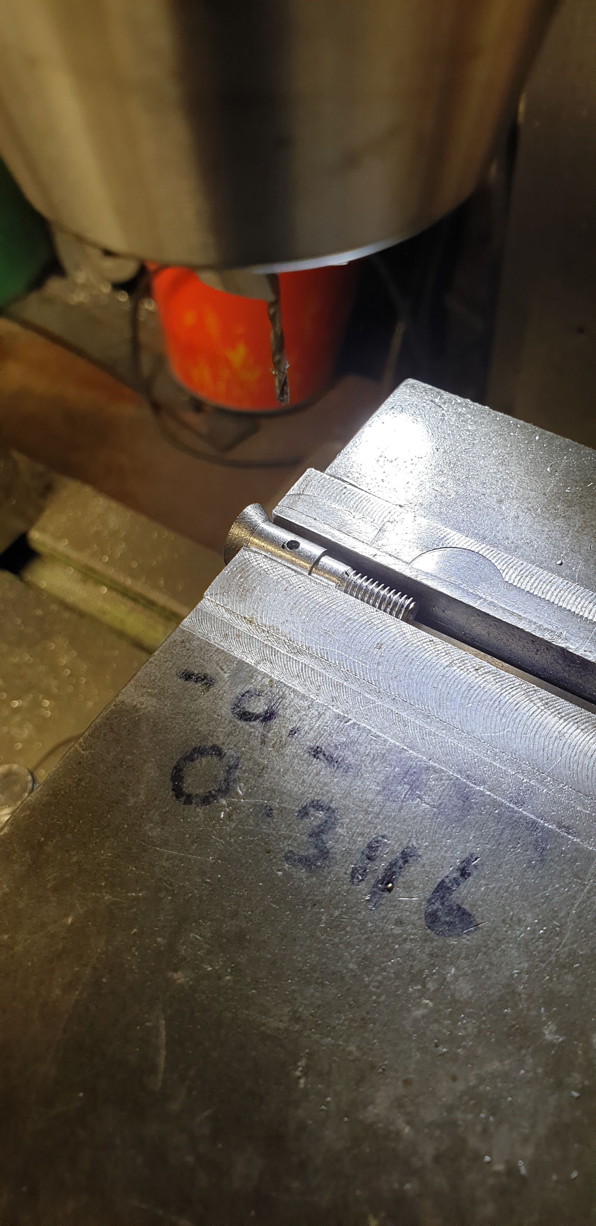
The connectors to fit the oil reservoirs began as brass hex bar, at short spigot was machined down to 2.3 mm and threaded 8 BA. This was then drilled 1 mm to a depth that would reach the cross drilled hole to meet it (forming an elbow) but not so deep as to make the overall size of the connector too big. After the spigot I left a small hex section and then turned down until the hex had gone, advanced on 'X' enough to have somewhere to cross drill and also leave some meat for parting off. I did do all this via dials so didn't actually note the dimensions, I was just working to make it look good enough. This was then screwed into the oil reservoir to clock where the cross hole needed to be for the pipe to be in its correct orientation. Once marked i removed the connector, held it in the vice and drilled by hand a 1mm hole until it met the other hole, I drilled these at a slight angle as the prototype isn't a 90 degree elbow.
The connector that fits onto the gudgeon pin is different in as far as it's bigger and rather than an 8BA spigot, it has an internal 2BA section that screws onto the end of the gudgeon pin. The same care was taken in getting the depth of holes correct while trying to keep the overall size close to scale. I haven't shaped this connector, leaving it circular for ease of maintenance. As for the pipe, this is soft soldered into the oil reservoir connector but left as a push in fit for the gudgeon pin connector. This is simply because it needs to be removable to be able to unscrew the connector from the gudgeon pin for maintenance of said pin. The tubes were formed without annealing, I inserted a length of piano wire through the tube, shaped it by hand and then pulled the wire out using pliers, this worked amazingly well.
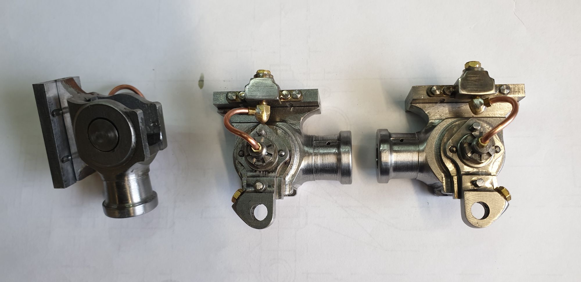
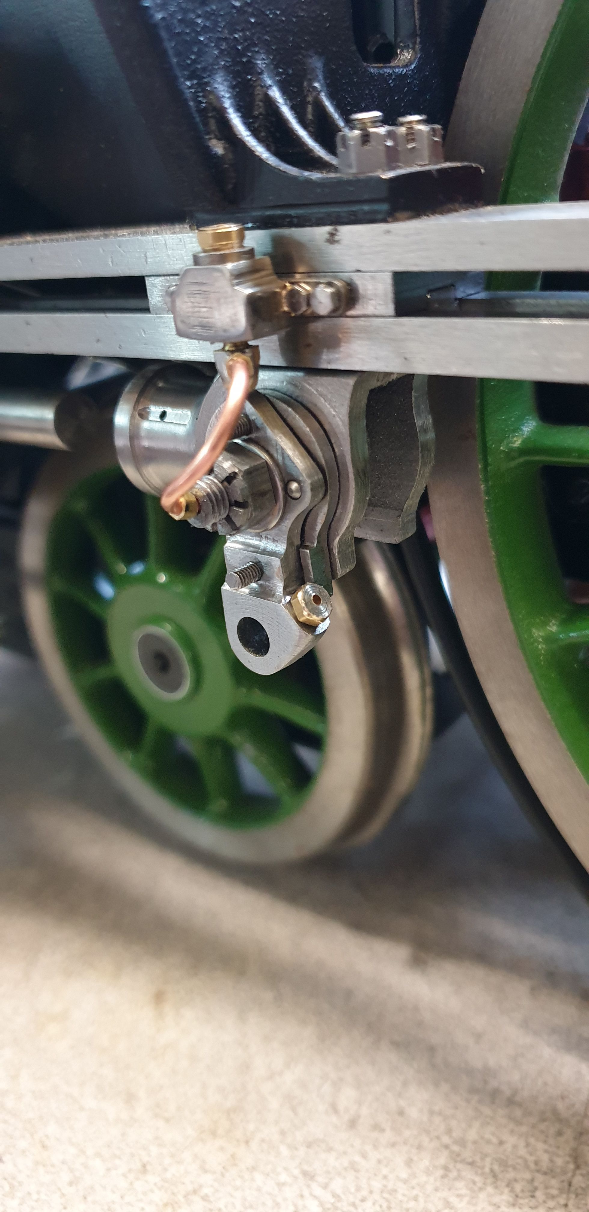
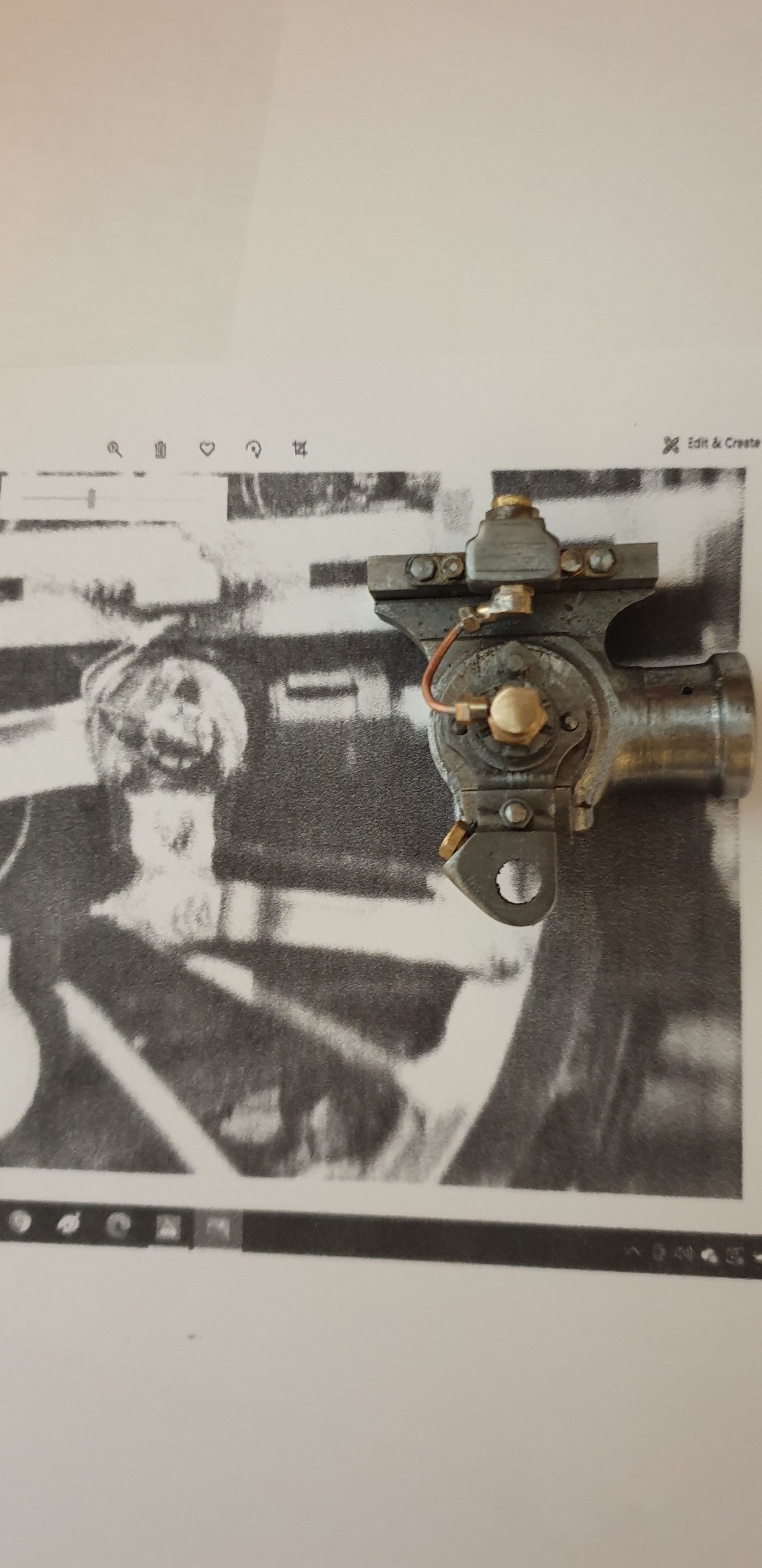
Ok, that was a lot to cover, I have one picture to show the end result which I have taken of the R/H crosshead as I have a picture of the same cross head from a V2. The V2 has the same cross head but instead of the union link pin being lubricated via gravity fed oil it's lubricated with grease via the grease nipple which can be seen where the angled oil reservoir is on 4472. Other than that, they are basically the same and thus I have tried to copy the pipe layout. The two connector types would very much warrant a 3D printed version, something for another day.
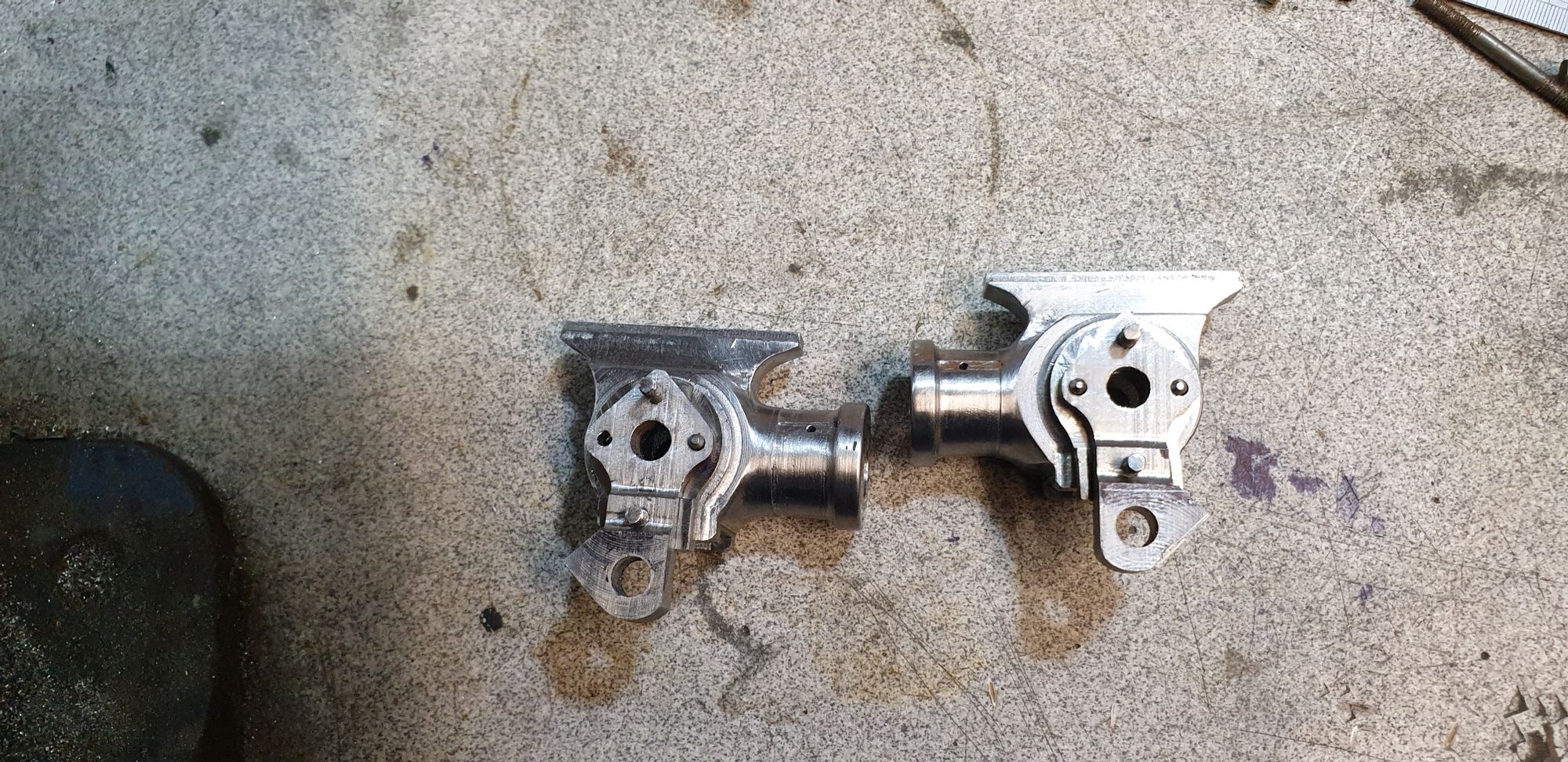
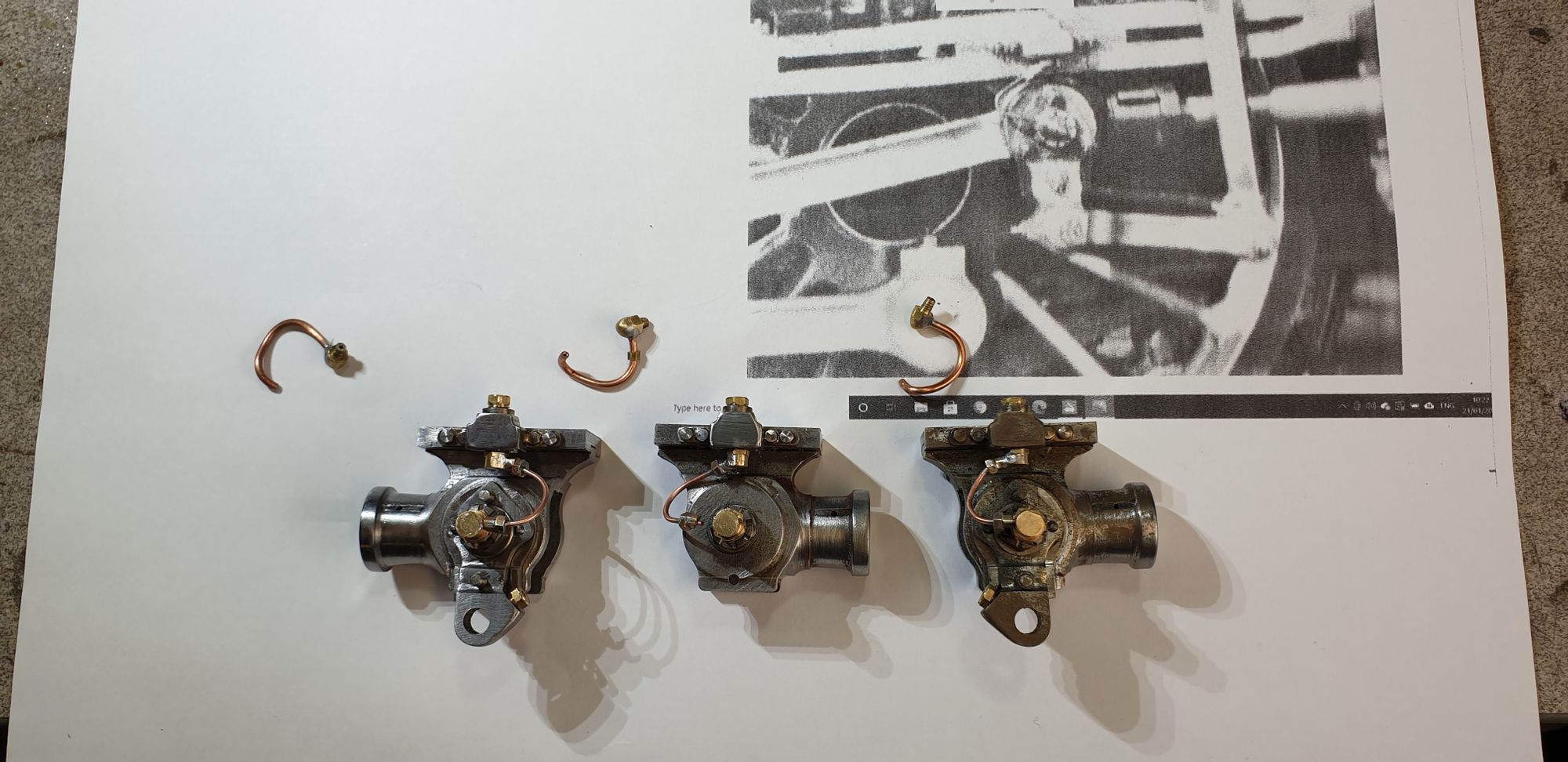
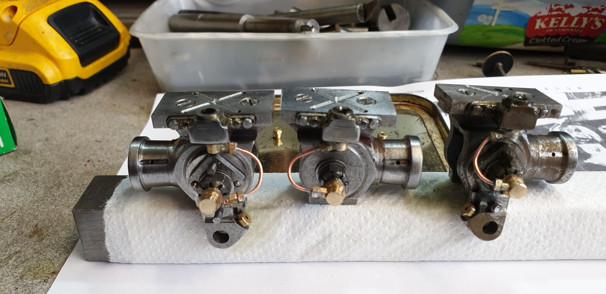
Crossheads now finished with the old oil pipes for comparison with the new
Oil test, with the oil reservoir caps removed i filled them with gear oil, the left hand oil pipe has been removed from the gudgeon pin connector to check that oil flowed freely under gravity, the oil is too clean to see clearly in this picture.
Video test using the oil can to force the oil through for the purpose of the test. You may recall that the oil reservoir openings had been made to allow the oil can end to fit/seal to be able to do this.