
As I have laid out before, 4472 (and for that matter, all Gresley A1/3's) have had a variety of different crossheads fitted during their career. The crossheads themselves are pretty much alike, the parts that are very different are the oil reservoirs and the drop link. Thanks' to Eddie Gibbon's vast research into these parts for his own superb builds of a K3 and H4 class loco's I could use this research to help in my own build. The 1934 pattern being the design chosen, this design can clearly be seen fitted to 4472 in 1935, 36 and 38 photo's and thus why I have modelled it for my build.
As stated, the crossheads are very similar, close enough for it to be very difficult to tell what was fitted but the oil reservoirs and drop links are much easier to see even in poor quality images.
Ok, so with the crossheads finished, I then turned my attention to the oiling system and to begin with made the oil reservoir which feeds to the small end bearing for the connecting rod.. For most of 4472's career (certainly under LNER rule) the oil reservoir was bolted to the out side edge of the slipper. This was first a round shaped reservoir and then a more rectangular shape with a stepped neck and rounded off sides. Today the reservoir is part of the drop link, sitting directly above the gudgeon pin, it's still rectangular but with sharp corners.
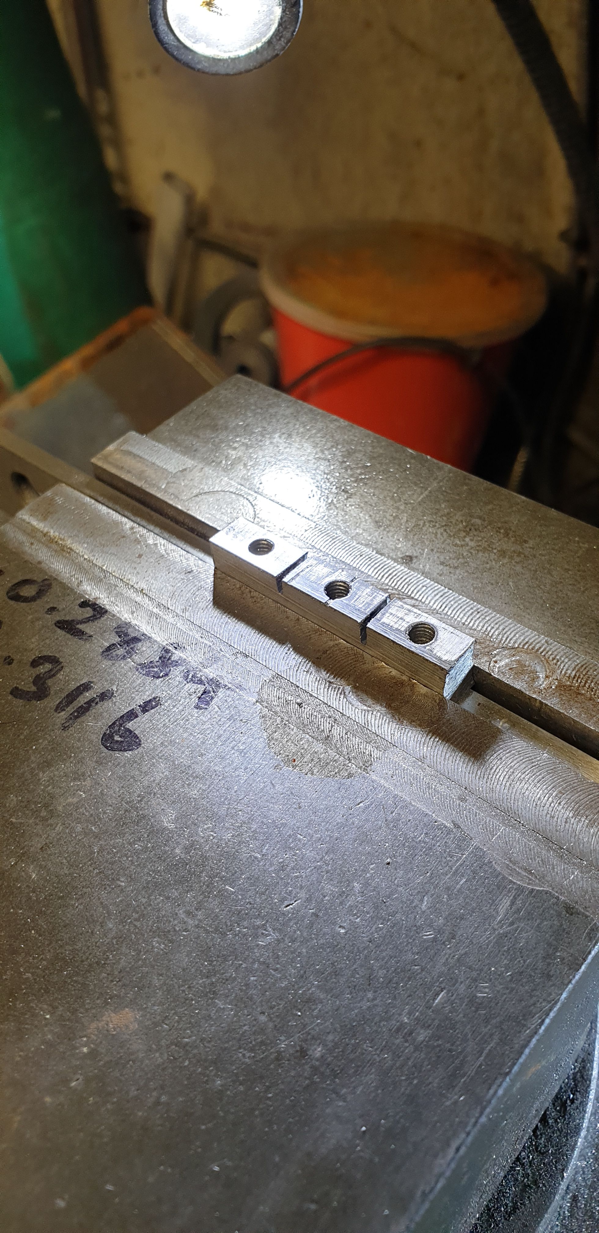
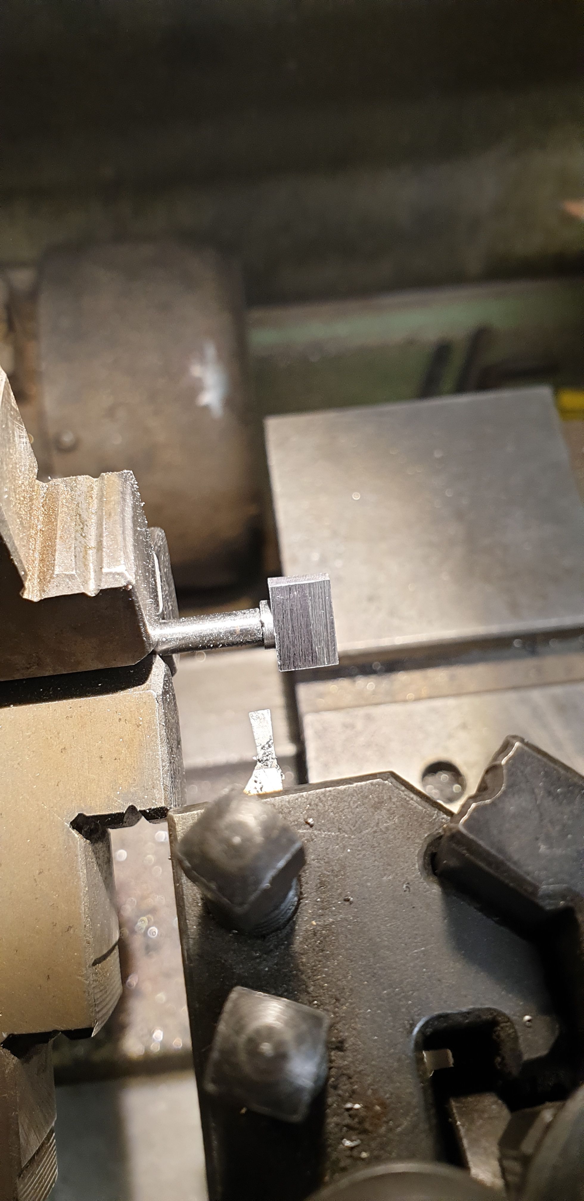
Using Eddie's drawing I first machined up a length of gauge plate to just over 0.300 tall and 0.250 wide, I then cut 3 slots with a hacksaw to divide them up, these are oversize at this stage. I drilled/tapped the centre's 5/32 x 40 TPI as seen in the picture.
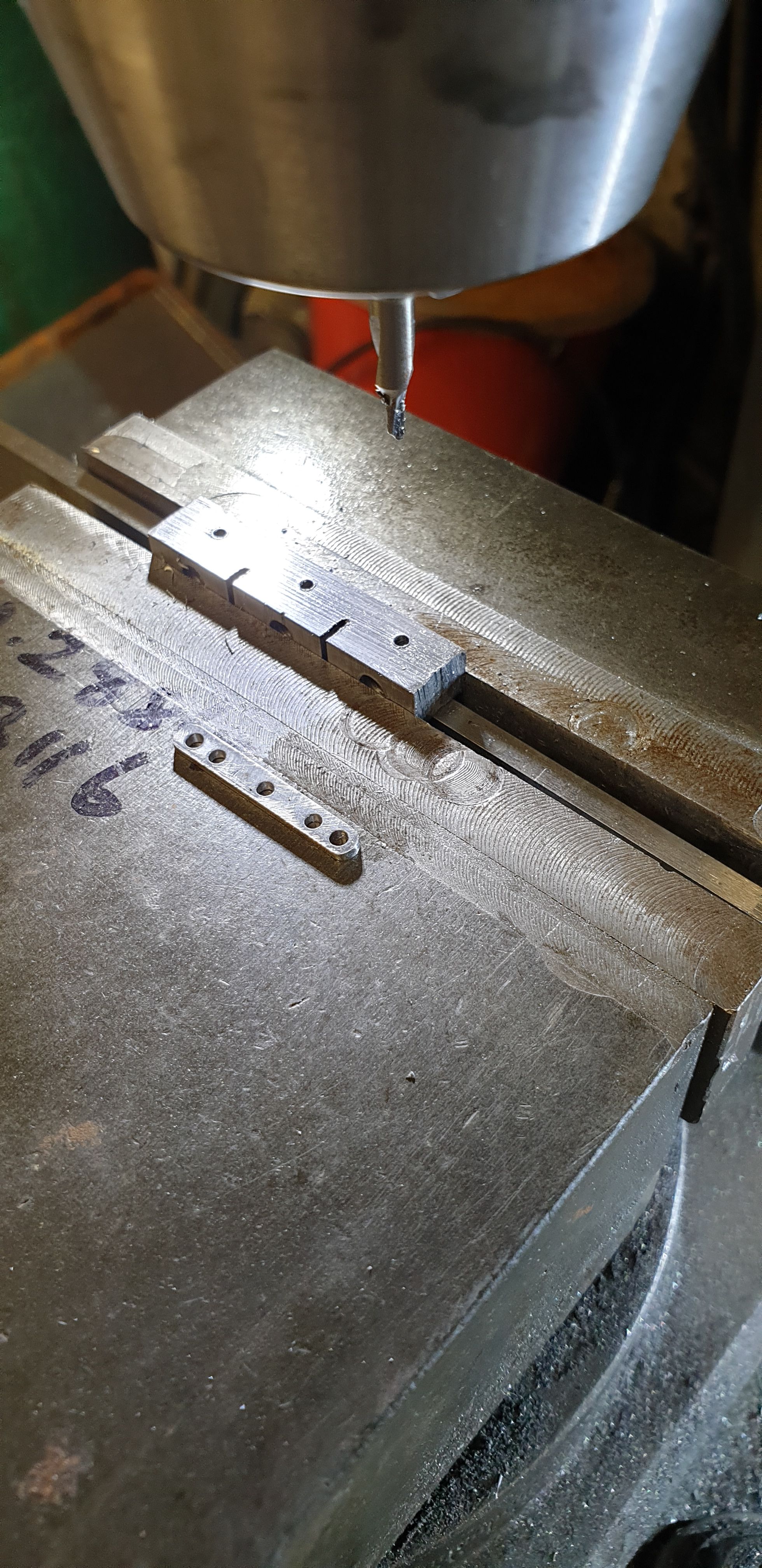
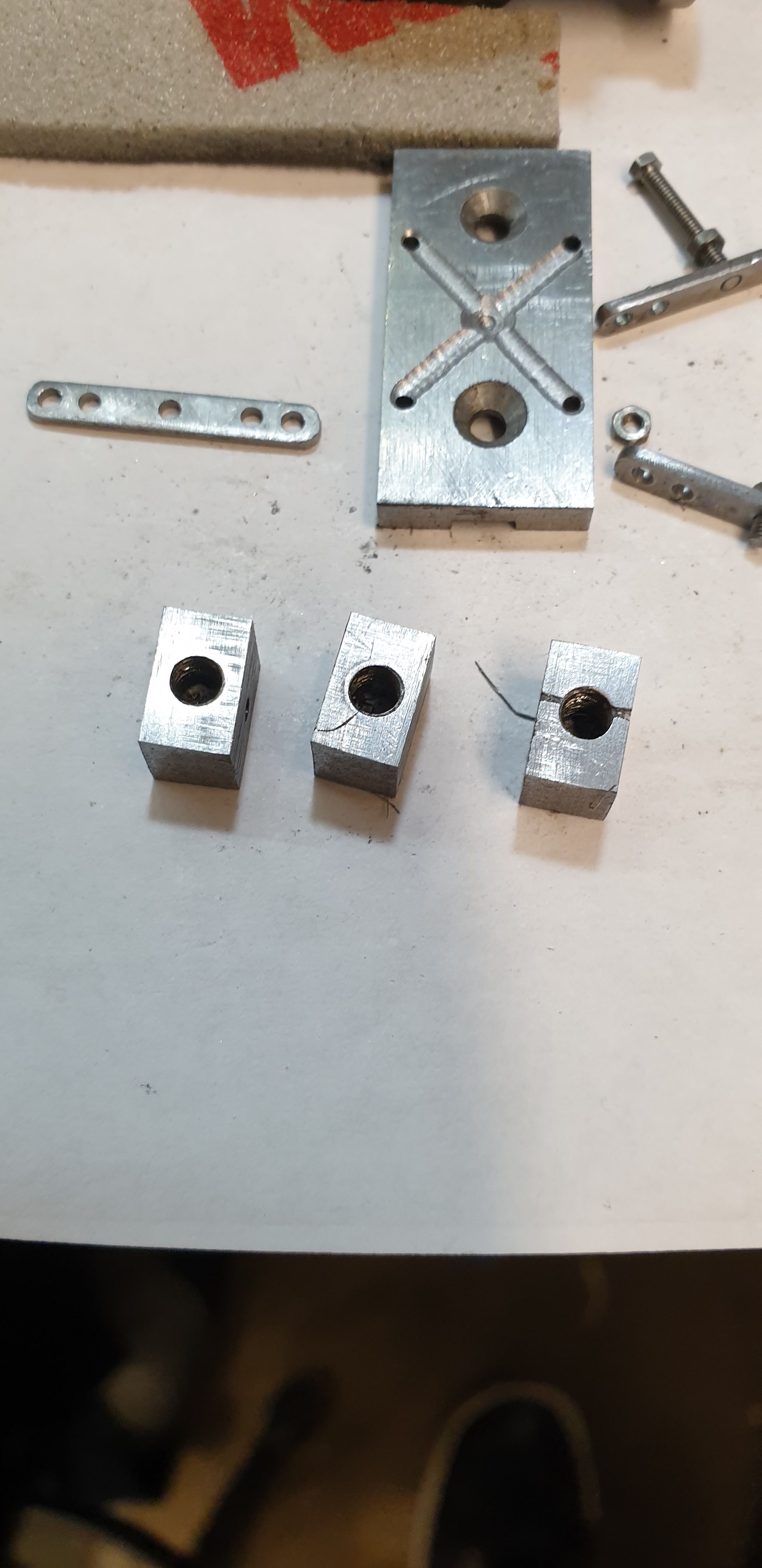
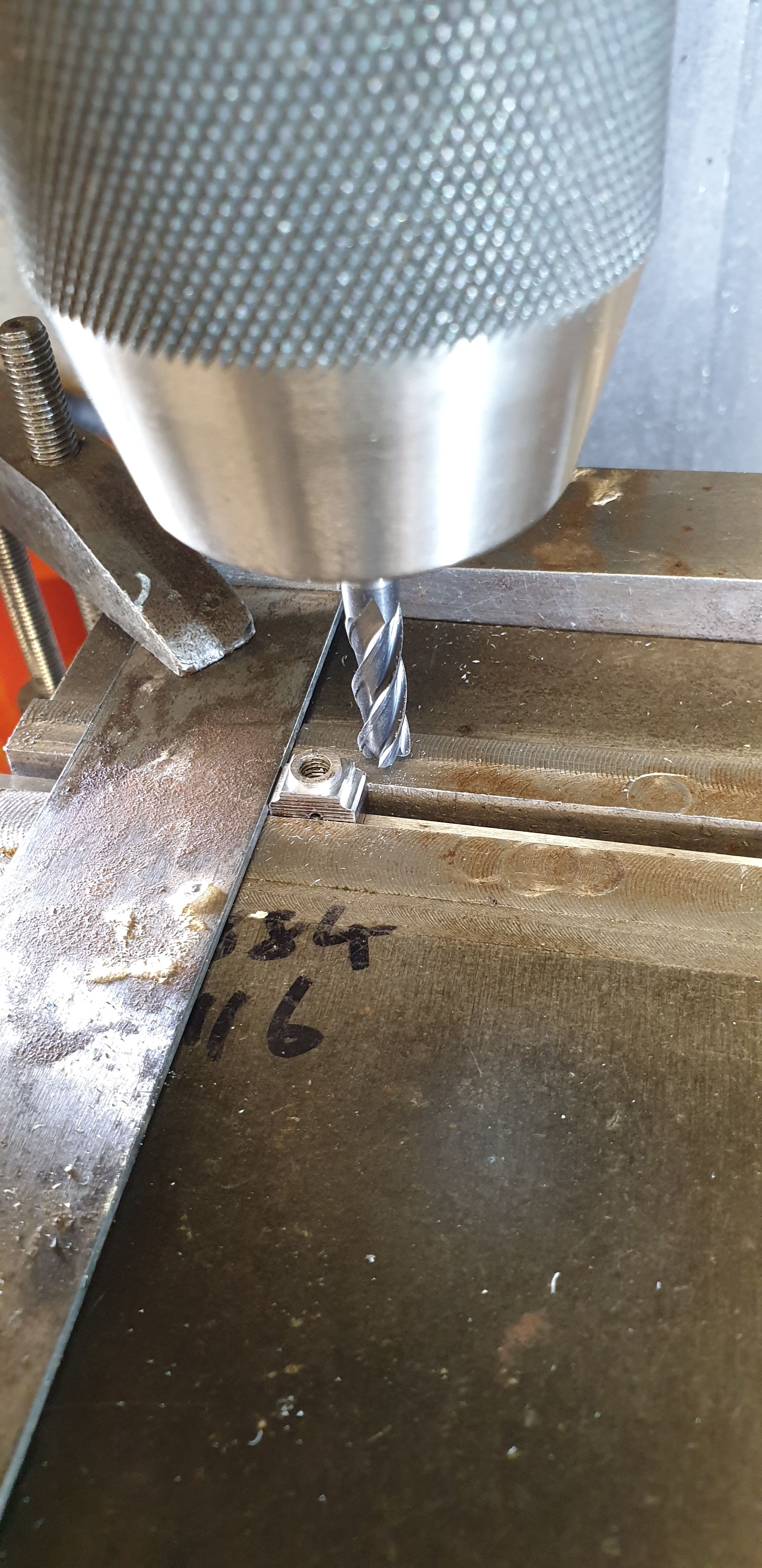
Then, thinking ahead to the metal mounting strip which will be silver soldered to the back of each reservoir, I cross-drilled each blank 10 BA for me to be able to bolt each strip to the reservoir. I have laid out one of the mounting strips showing the 4 holes for the bolts to hold the reservoir to the slipper but also the middle hole for me to bolt to the reservoir body for silver soldering. BTW, the strips are lengths of steel that was left over from when I made the draincock linkage, they just happen to be the right size.
Here we see the 3 blanks now parted and ready for the next stage.
That stage involved machining a small collar around the 5/32 x 40 TPI hole. For this I threaded a length of 5/32 silver steel and tightened each blank up tightly for the part to be turned on the lathe.
Now, these reservoirs aren't simple rectangles with rounded edges, they have a step on each side with two different angles. The base is also angled out from the centre, IE, it's not flat. The bottom face I ground on the belt sander having first marked it out. Before doing that, I marked out the rough shape of the sides and using a 6 mm cutter machined away most of the access material leaving me a sharp corner to give me a datum from which I could hand file the two angled steps from.
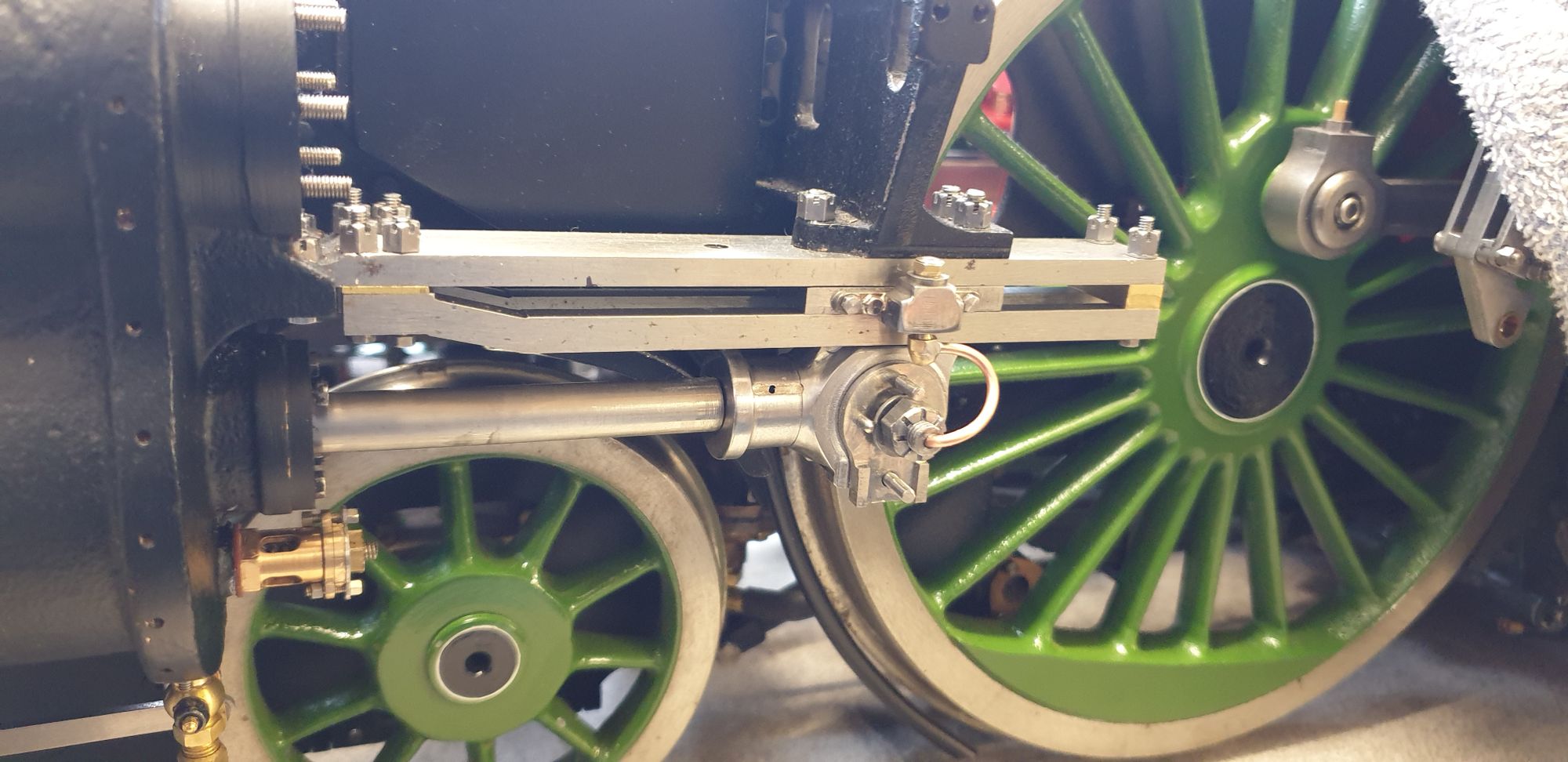
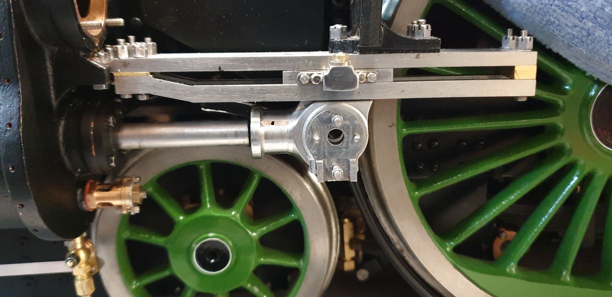
It was then back to the Dremel with a variety of diamond grinders and polishing discs to complete the shape. This took some time but I think it captures the overall shape of the 1934 reservoir. Here's a picture of the left hand outside cylinder with it's crosshead temporarily fitted to check it's look. I'll also point out that the crosshead side top edge (under the slide bar) has now been rounded to match the prototype. I will point out ( just visible in this picture) the oil plugs that were turned up from 5/32 brass hex and given a matching thread. I also machined a very small step just above the hex as a plain hex looks wrong. A small hole drilled in the centre stops any possible vacuum lock.
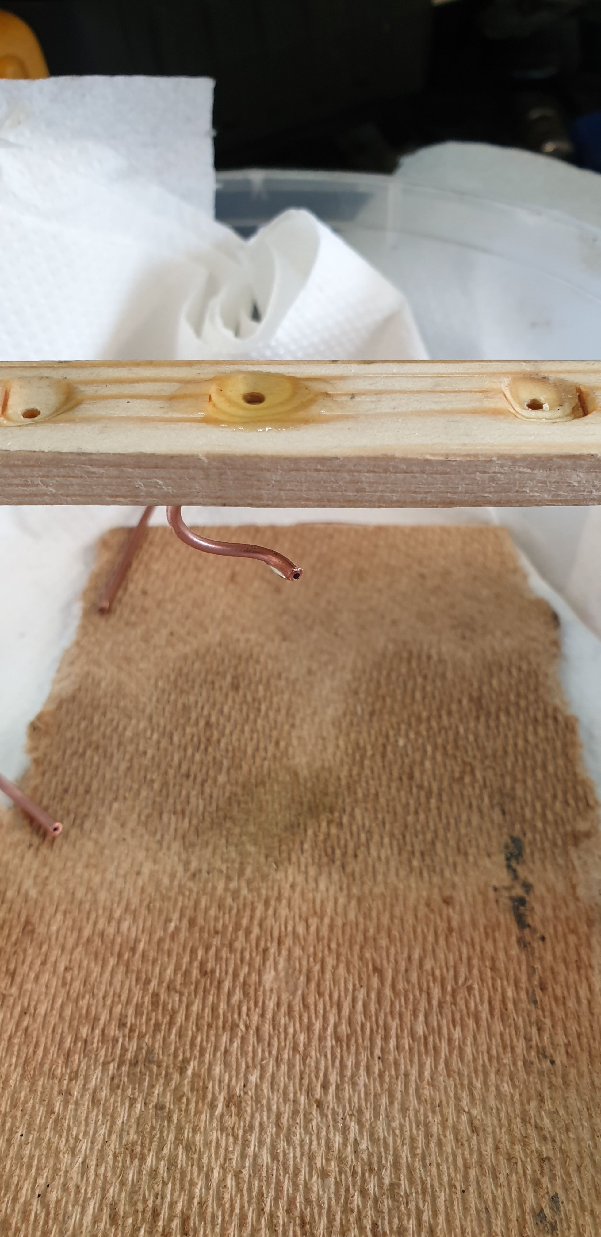
Next job was to make the oil pipes, for these I did a quick test on two different sized copper pipe, one with a bore of 1 mm and the other 0.6 mm. The smaller size is closest to scale. At first I thought that this might be too small for a practical gravity oil feed pipe but this assumption have proved to be wrong. having seen how well the oil flows ( it's lathe gearbox oil so not that thin) I will probably now use this size throughout the oiling system. A short video.
Here are the crossheads so far with their oil pipes partially fitted. I drilled/tapped 7BA the bottom of the reservoirs and made up some brass nipples for the copper pipe to be soldered in to, angled forward as mentioned earlier ( NB this is wrong, it should be facing the rear, I'll correct that later) . These are a little overscale and not exactly as seen in the fuzzy photo's which I have but I think they will work. The full size photos clearly show some form of brass fitting at both ends of the pipe, I'll make the other end once the gudgeon pins are made as it needs to fit into the pin.
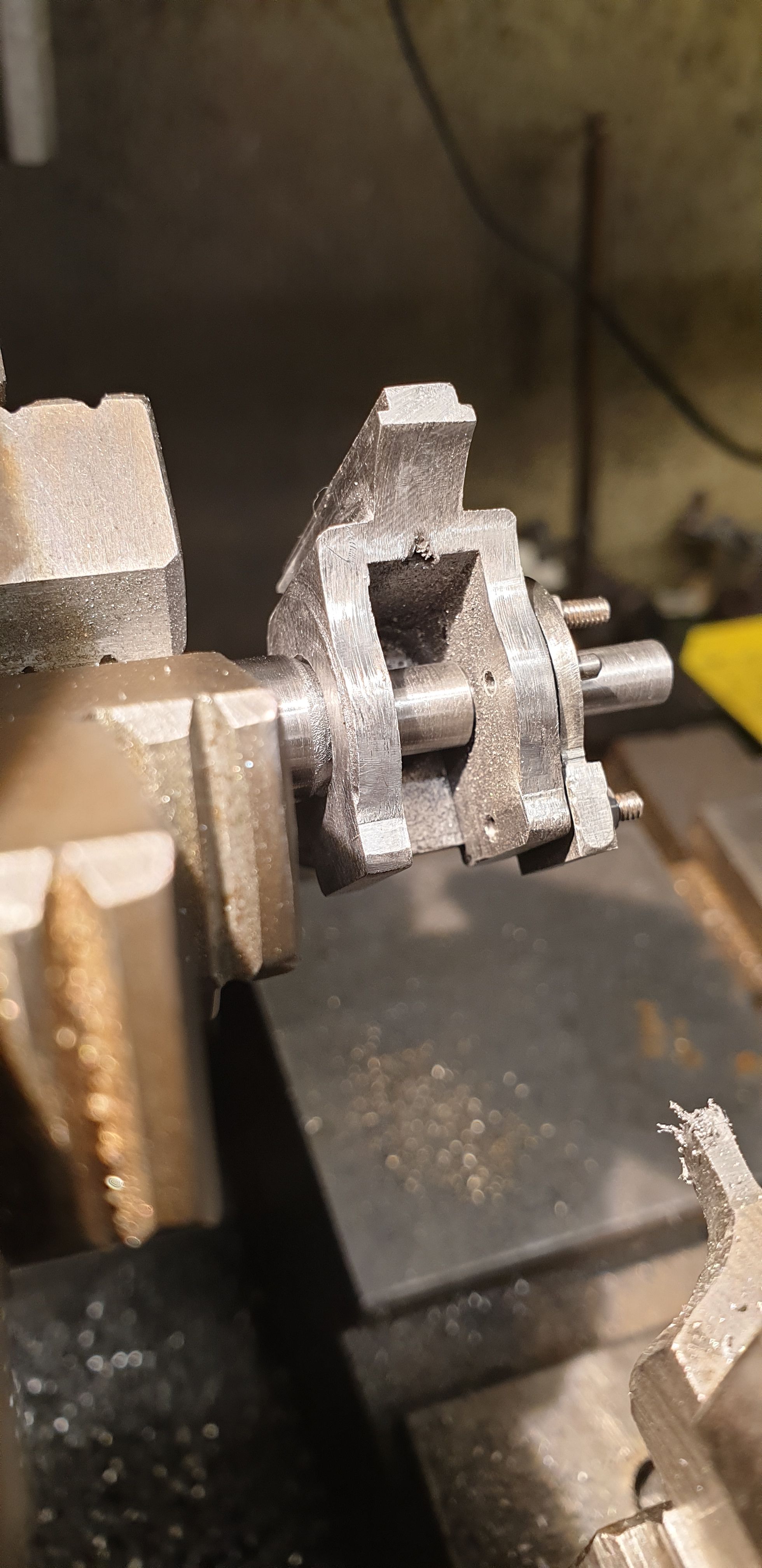
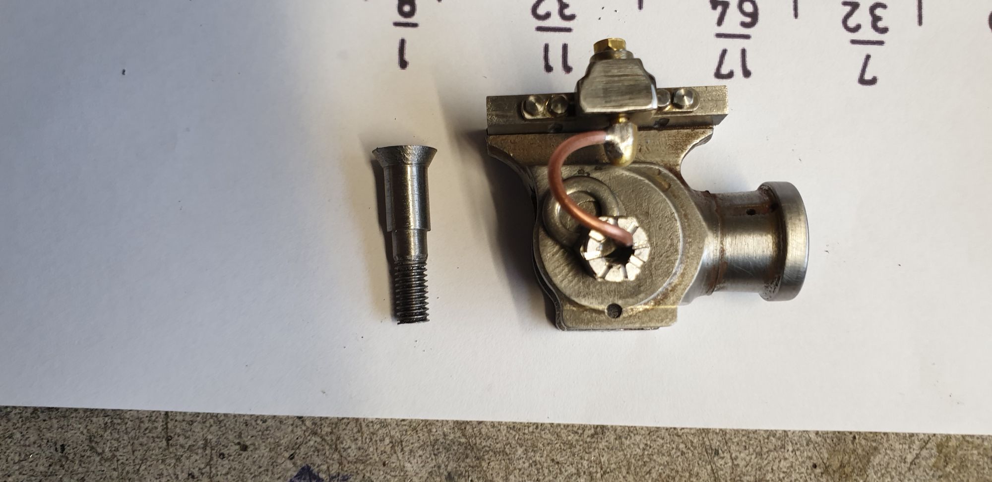
On to the gudgeon pins, I won't give many pictures here as it's basic turning but I will explain my sequence of turning them. First I cut 3 lengths of 0/412 silver steel or should I say that I thought it was silver steel, going by how it machined I suspect that a length of EN8 found its way into the silver steel tin? Either material is fine with EN8 being overkill. Ok, so I first roughed out a spigot on each to 0.270 ready to finish at 0.250. I then finished each pin to it's 0.250 dia to fit the rear of the crosshead. I checked each with the crosshead for fit. Next up was the 30 degree angle on the end to fit the CSK in the rear face of the crosshead. each pin in turn was reversed in the chuck, top slide set to 30 degrees and machined. It was then time to machine the 0.200 step for the pin to fit through the front of the crosshead, mounting plate and when made, the drop link. This was the first time that I could properly try each crosshead for fit, the next picture shows such a test fit. Note that the pin isn't fully engaged yet, you can see a small gap at the back and also where the 0.250 little end journal hasn't quite touched the front inside face. This is a judgement call knowing that when the nut is fitted and tightened it will pull the pin in further than I can push it on.
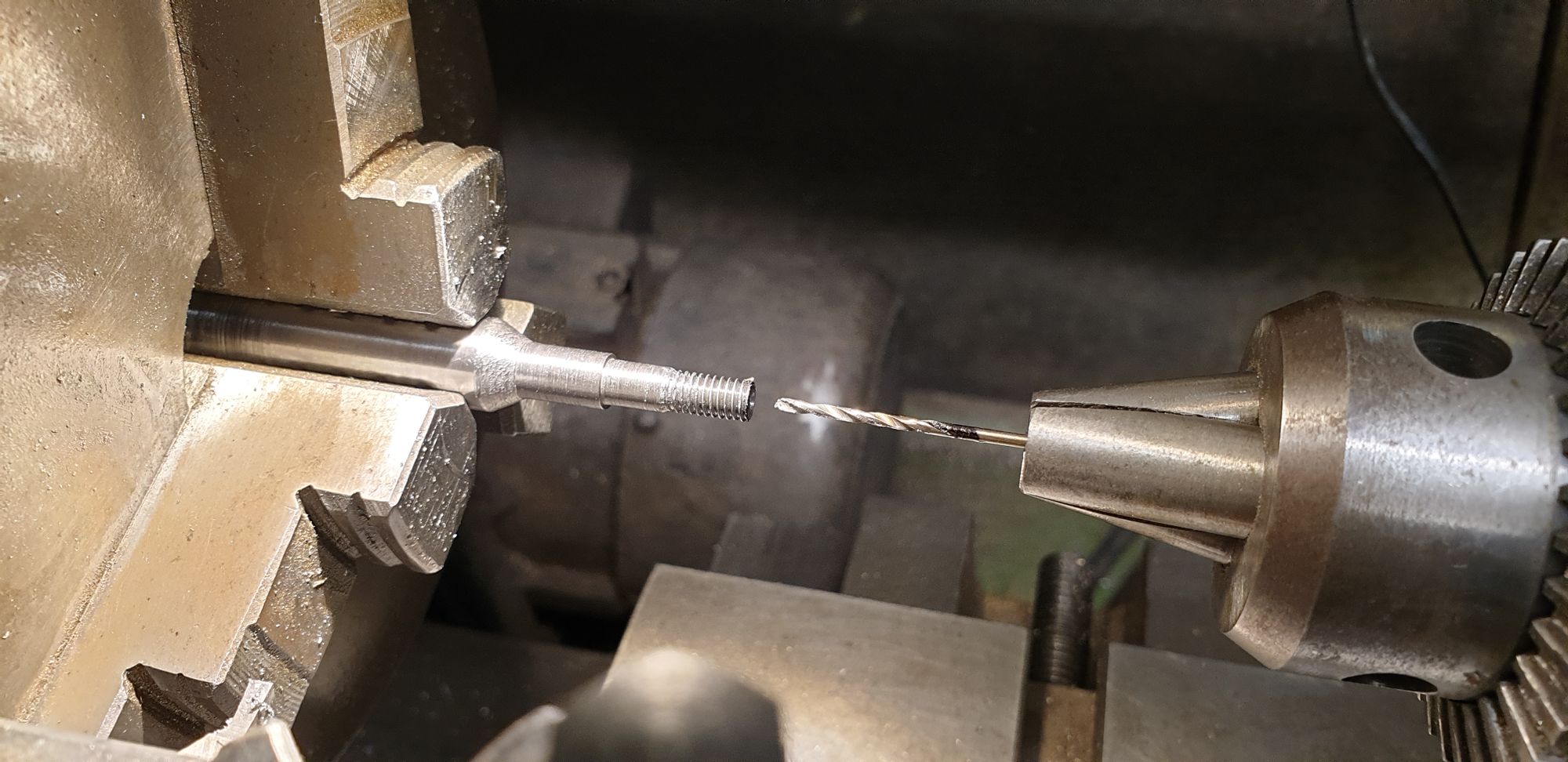
I then moved on to the 2BA threaded section, first I needed to work out how far to machine the 0.200 step which locates the crosshead, mounting plate and drop link. I studied the 1934 drawing first to note the width (thickness) of the drop link and thus judge how much of the step was required. The remaining section was machined down for the 2 BA threaded end, this was also cut down to length, I have left it overlength until these other parts had been decided on. With the threaded section cut I had one more turning exercise to do, this was drilling the oilway hole down the centre. It was at this point that in hindsight if doing these again I would drill this hole first, even more so when using EN8. The size drilled is 1.5 mm using a cobalt bit, the hole was drilled until it reached just under half way into the 0.250 journal. Reason for not going to the halfway mark is because if you recall I have changed the design a little here and part of the journal is within the CSK hole in the rear face. I saw this as better than having the 30 degree chamfer going all the way through the rear face. Hope that makes sense?
The nuts again were simple turning and threading 2 BA, I have followed full size and machined a collar around one end which will also be castellated soon. Unlike the other castellated nuts machined so far, these will have 8 slots instead of the usual 6. In the picture, the two on the right have had their central oil way drilled, the one of the left is awaiting the same exercise. Once I have drilled the cross-drill oil way in the journal I'll part off to size.
I then did another test of the oil pipe which now had it's bend to fit the end of the gudgeon pin, this time it took 3 mins. going from this I expect that the oil will take between 4 to 5 mins to reach the small end journal. I think that this should be fine, the oil reservoir cap when removed gives me enough room for my pump-action oil can nozzle to fit snugly in it and thus I can pump oil until it's on the journal for each steaming session. The oil reservoir should then hold enough for a fair amount of steaming time.
The gudgeon pins were then parted, here we see the middle cylinder with it's (shorter) gudgeon pin alongside.
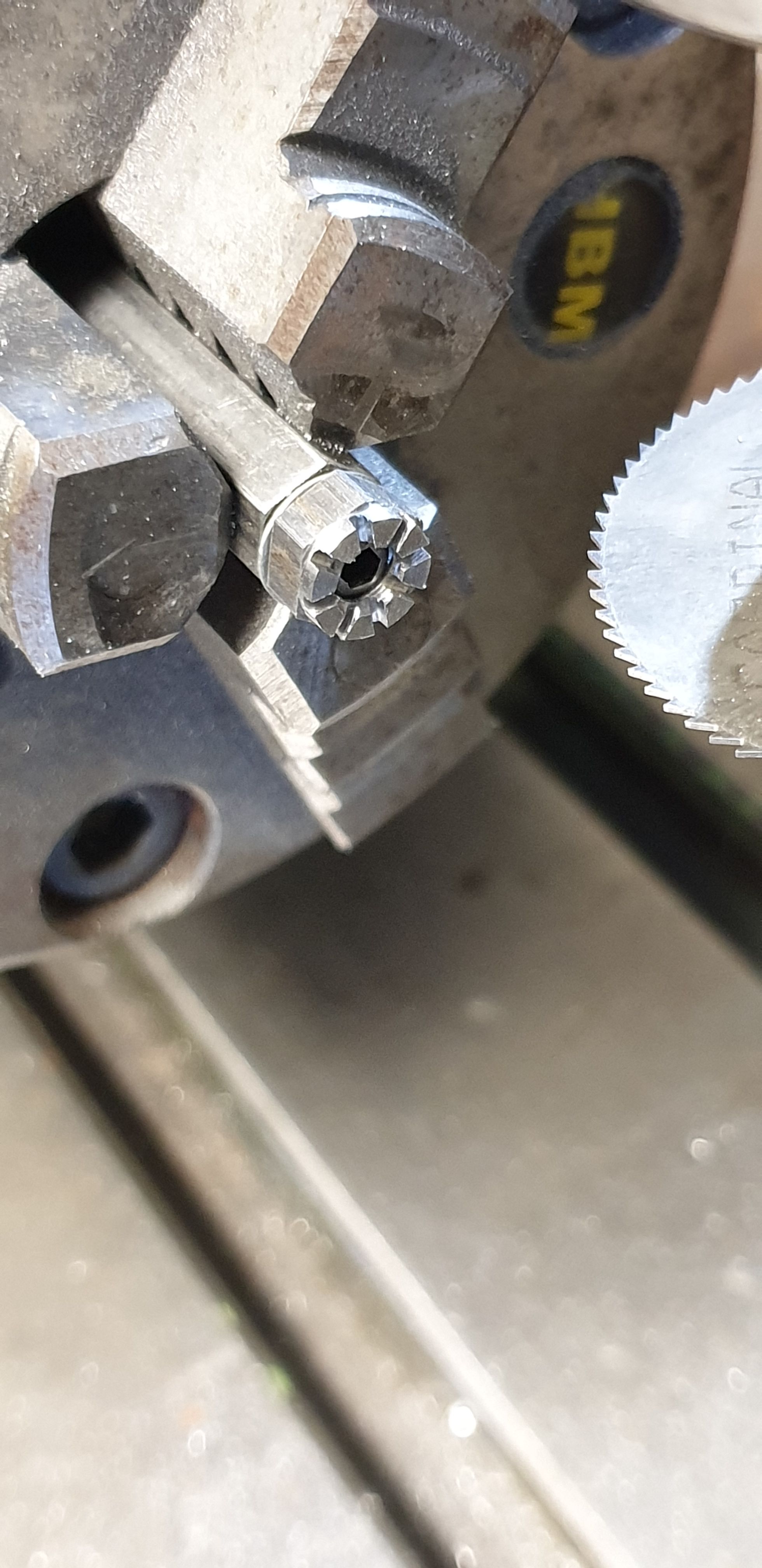
The nuts were then set up in the rotary table and had their slots machined, in this case there are 8 slots compared to all other castellated nuts made so far with only 6 slots.
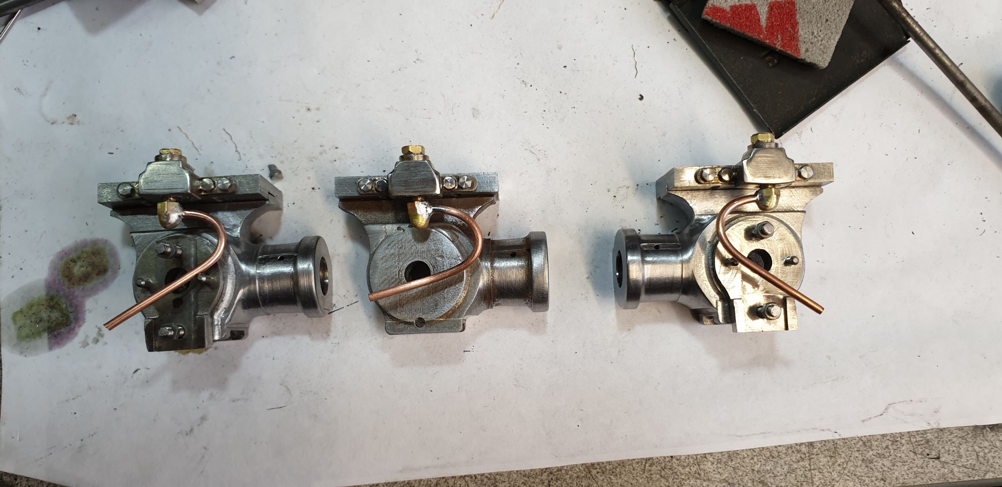
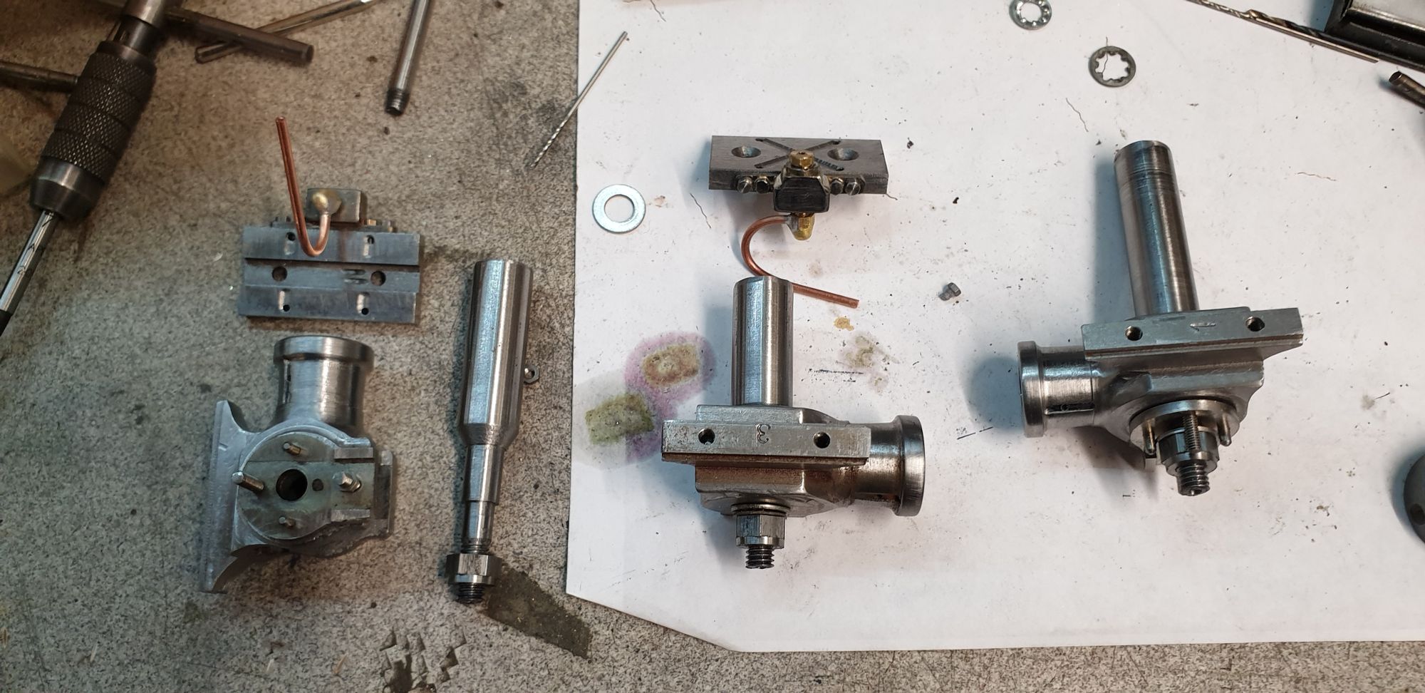
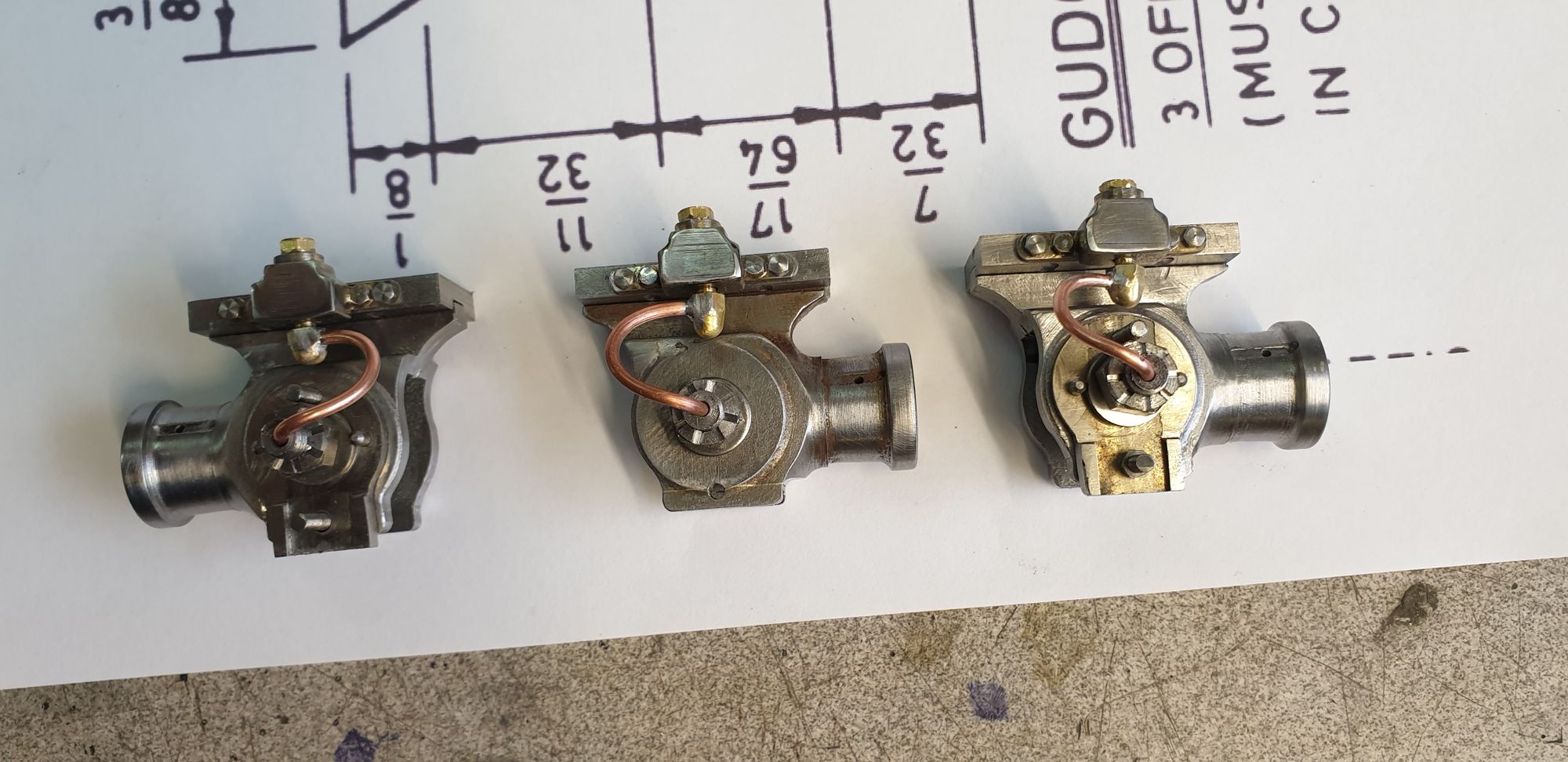
The 3 finished crossheads, from left to right we have the L/H outside crosshead, middle crosshead and R/H outside crosshead. i have one more machining operation to do on these and that's to cross-drill the gudgeon pin journals.
Lastly, the money shot, here's the L/H cylinder with it's finished crosshead siting in its slide bar.

with this some what herculean task behind me I can now move on and make the drop links, only two as the middle cylinder doesn't require one, which I'm sure you guys will know why not?..:)
Next as stated will be the drop links, followed by the outside connecting rods (middle was machined some months ago) and all brasses for the three connecting rods. Once those are done I'll spend a fair amount of time ensuring that the slide bars are correctly aligned and that the crossheads slide in them freely. I will then fit the connecting rods and calculate the length of the piston rods to set up the piston 'stroke' correctly. Final job being to fit the piston rods into their respective crossheads, drill/taper for 1/16 taper pins which will be designed to look like cotter pins.