This entry see's the completion of the main crosshead body and their mounting plates, 4 weeks solid work? The middle crosshead is a little more simplified as it has no drop link, I have simplified it a little more by not machining the lower tab which the mounting plate would have bolted too. For this crosshead I have just machined the round raised boss. The oil reservoir will be covered later but I can say that I'll follow the same design as that applied to the outside cylinders, IE: the reservoir will be bolted to the slipper on the gudgeon pin nut side and a small oil pipe will drop from the reservoir into the gudgeon pin. The pins will be drilled to approx the middle of the little end bearing and then half cross drilled for the oil to reach the bronze bush, more on this later.
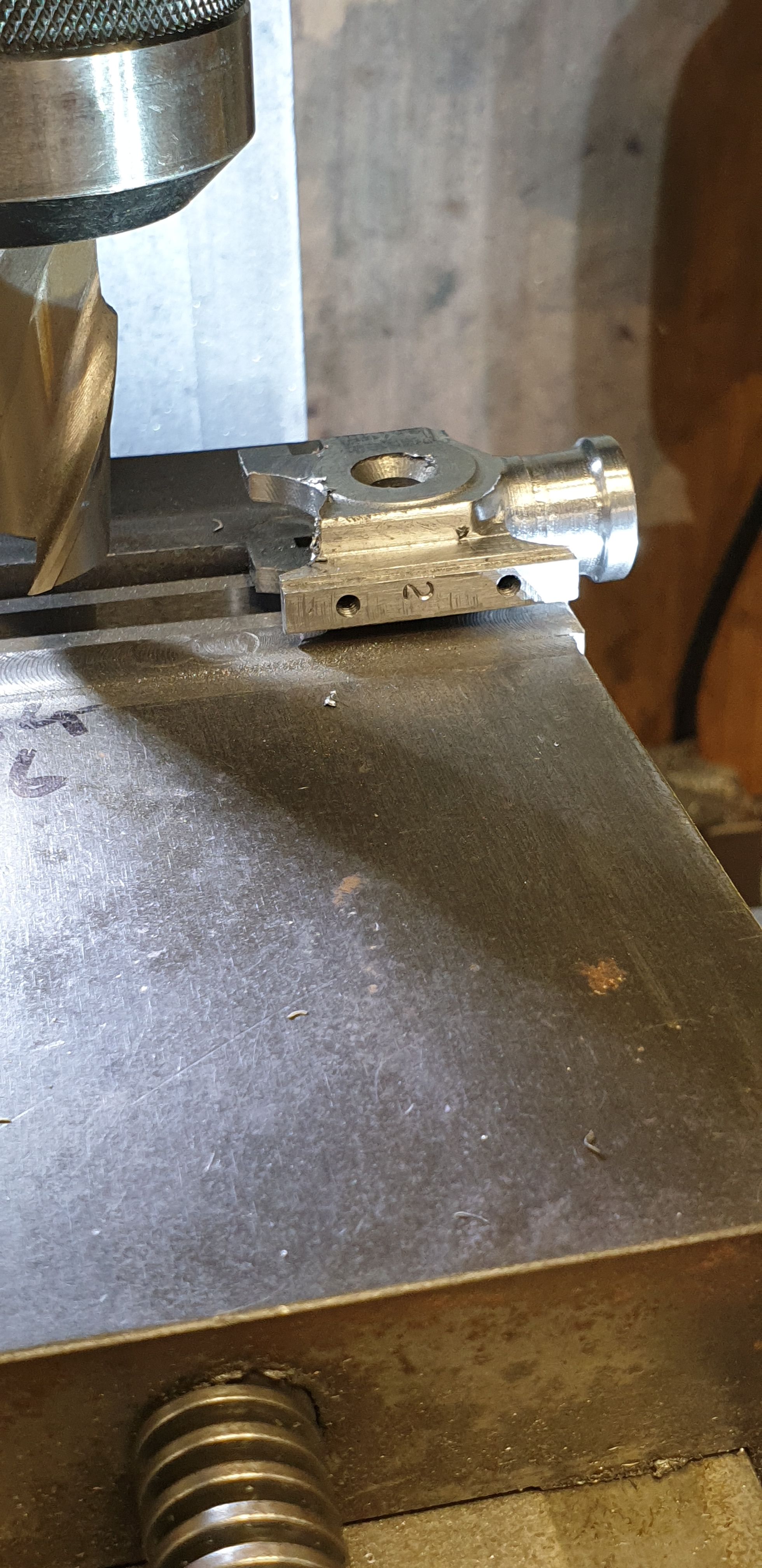
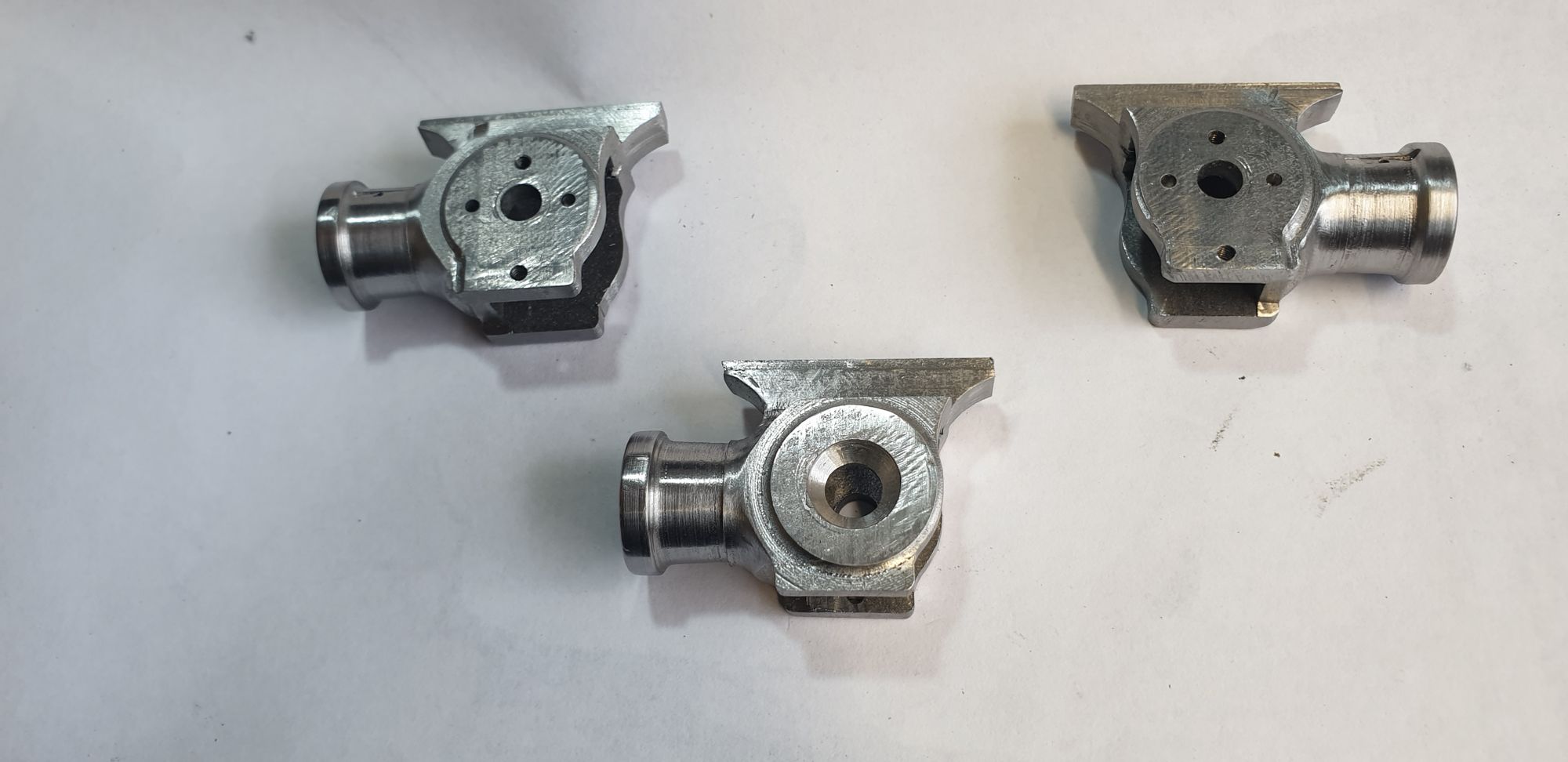
I'll include two pictures to show the difference between the simplified crosshead and the other two. This picture shows the middle simplified crosshead, as you can see I have machined a complete circle for the raised collar using the smaller button for guidance. This collar is a little shallow when compared to full size but I am restrained in needing to stick to the model overall design and it's dimensions while trying to emulate the prototype. I think it will look fine once fitted to the model.
Here we have one of the outside crossheads with the extra area left which the drop link mounting plate bolts too. This is very much at the roughing out stage, once all of the machining is finished I'll then smooth everything off and get the look as close to the prototype as possibly.
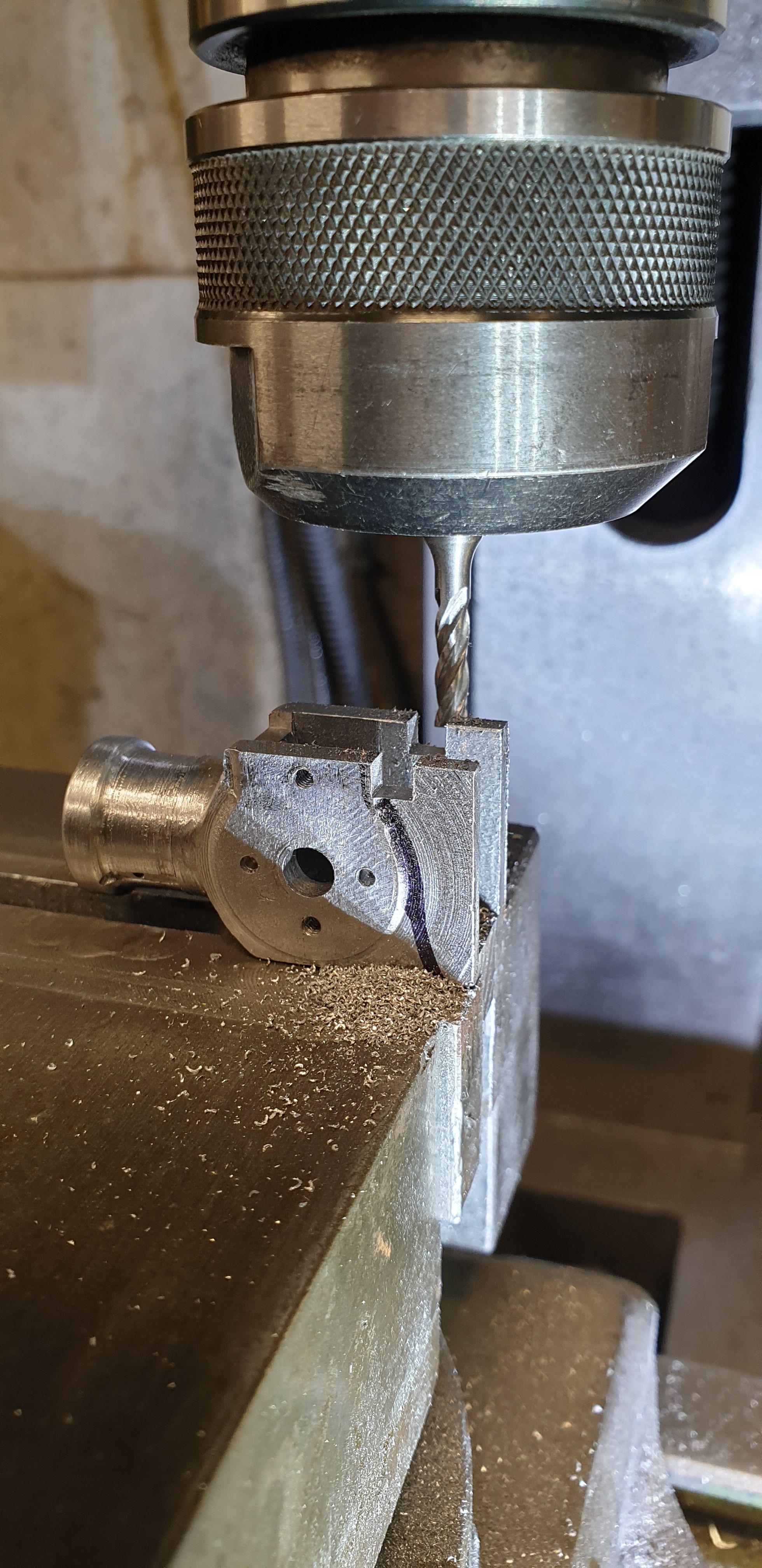
It was then back to the machine vice to do some of the last machining operations for the crossheads which in this case involves shaping the rear end.
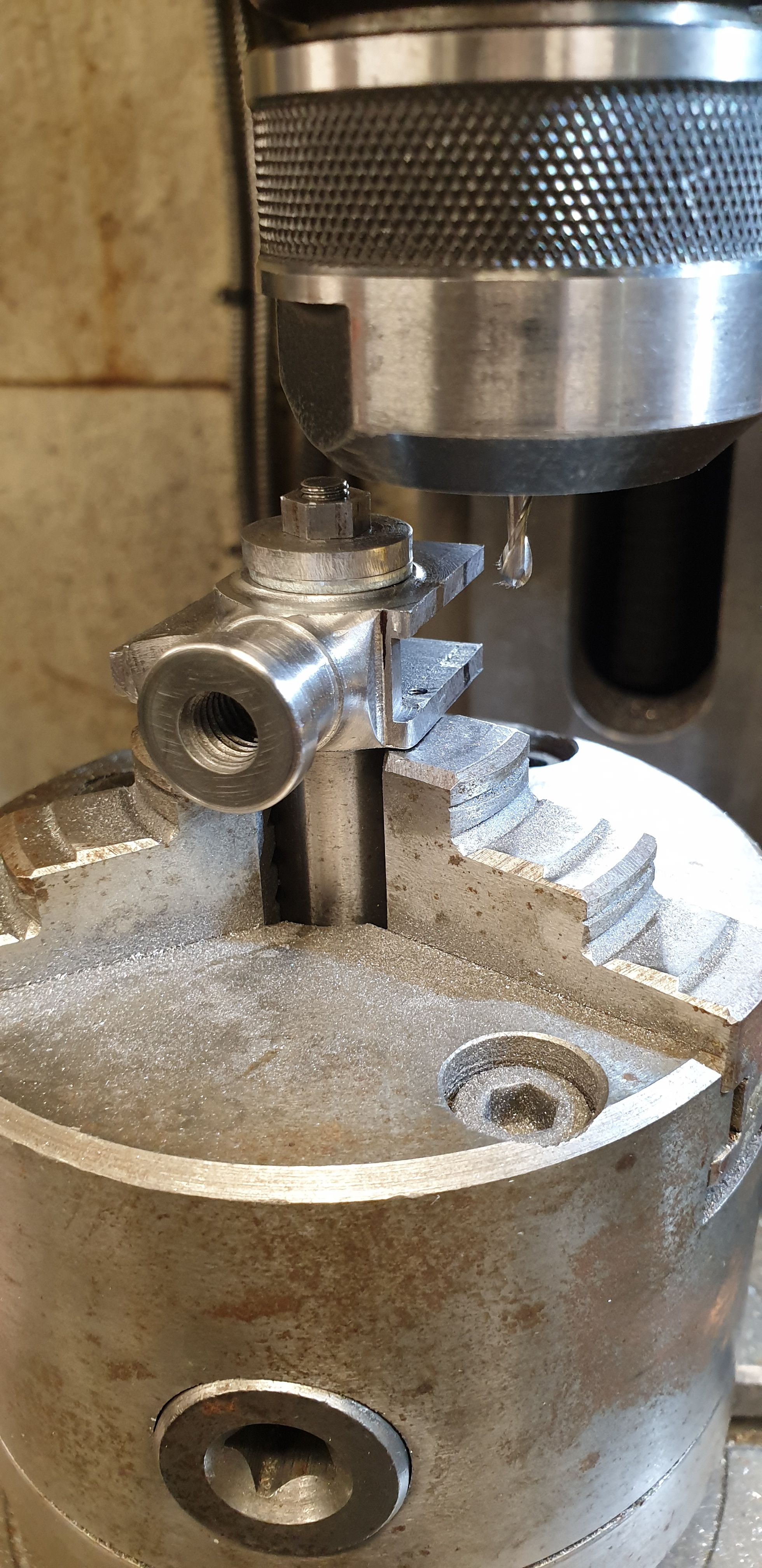
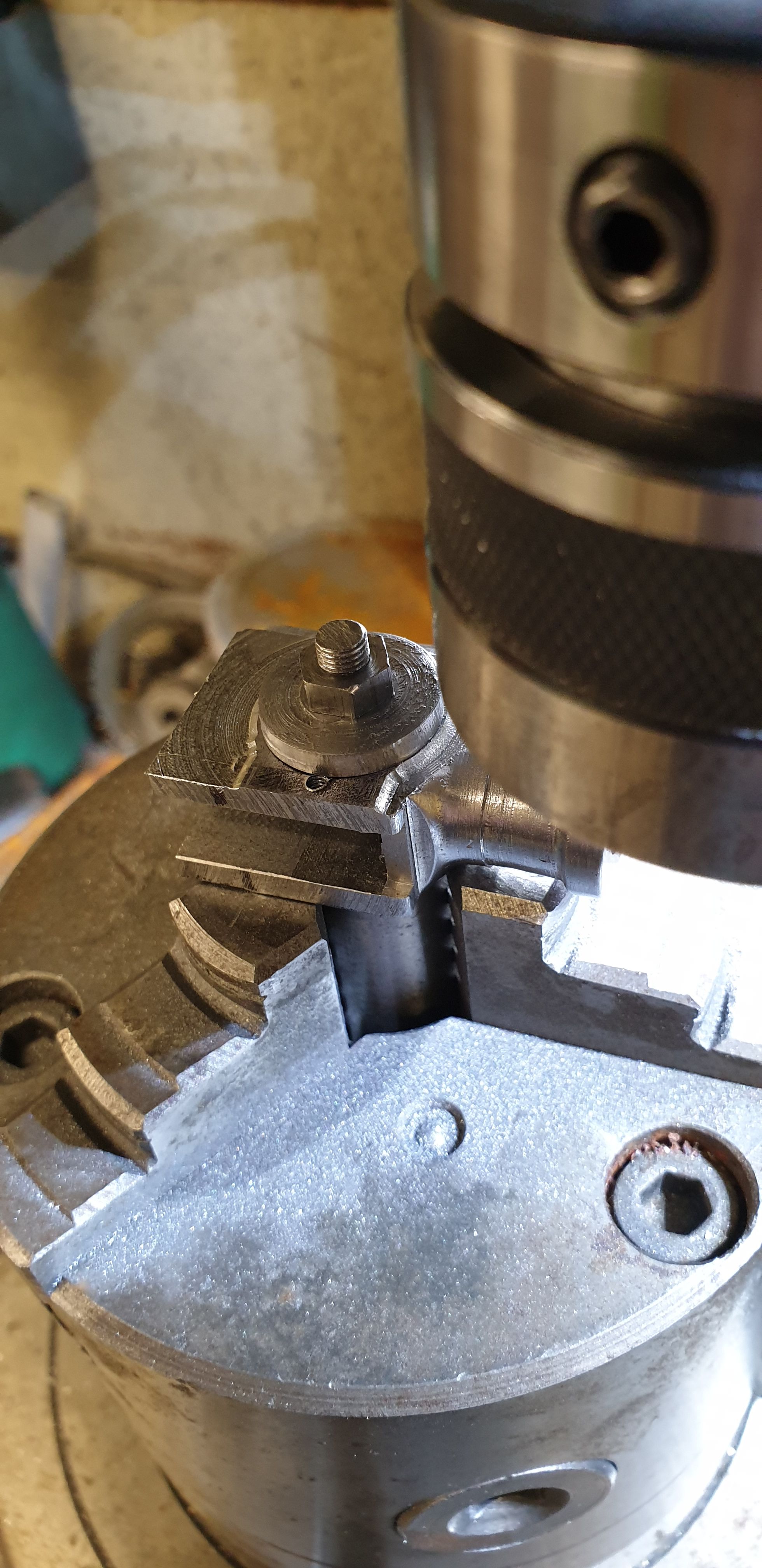
This is how I tackled this stage, first holding each crosshead upright in the machine vice I cut a slot at the back edge of the mounting plate raised tab. To make life easier each crosshead was set up against the far edge of the vice and once machined the next was put in the same position thus making all slots the same. I didn't take the slot right down to the round part, I'll do this when back on the rotary table. I have penned a rough line to show what needs to be removed.
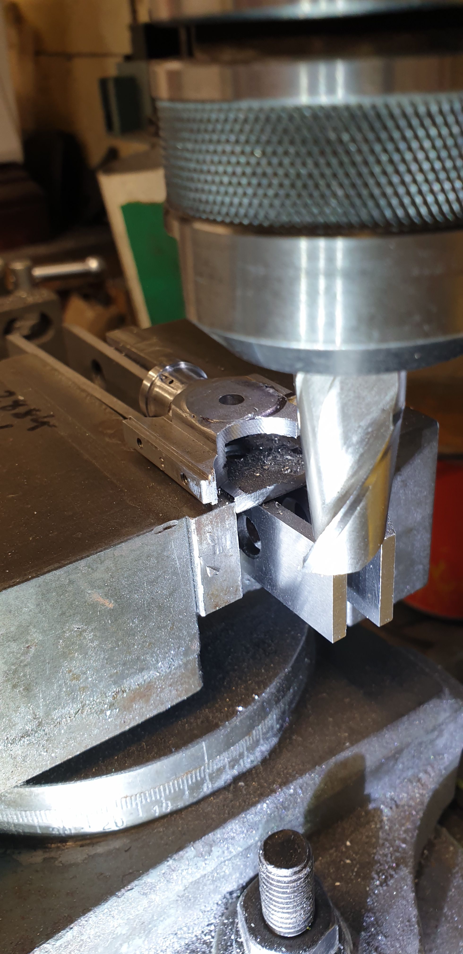
It was then the turn of the large radius (19 mm cutter) which goes from the back of the curved raised collar to the underside of the slipper leaving a small area un cut. Again, to get all 3 crossheads the same and to ensure that the cuts matched either side I clocked the crosshead against the edge of the vice, locked 'Y' axis and slowly machined the rear, taking first 10 thou and later 15 thou deep cuts. I machined this down past the half way mark, I took it all the way through the slipper mount which meant that I could eyeball when machining the other side to ensure all was the same. I also noted how much the cutter advanced from first touch to meeting the raised collar for when machining the other side. Hopefully, the picture shows what I am trying to describe. This picture also shows what remains of my hickup in machining when not gripping the part properly, barely a mark now, I could fill it with solder, or leave it as a battle scar.. just like the real thing...:)
It was then a simple task of flipping each crosshead and mounting it facing the opposite direction. As stated, 'Y' is locked so this will ensure that the cut curves match either side. I then proceeded to cut as with the first side and this time noting the distance the cutter moved along 'X' once it touched the metal, the figure taken noted before was used to get both sides the same. Note, I am talking the distance travelled, not the actual DRO reading as this is now different, I didn't reset 'X or Y' as they were still zeroed for the rotary table which would be needed again next.
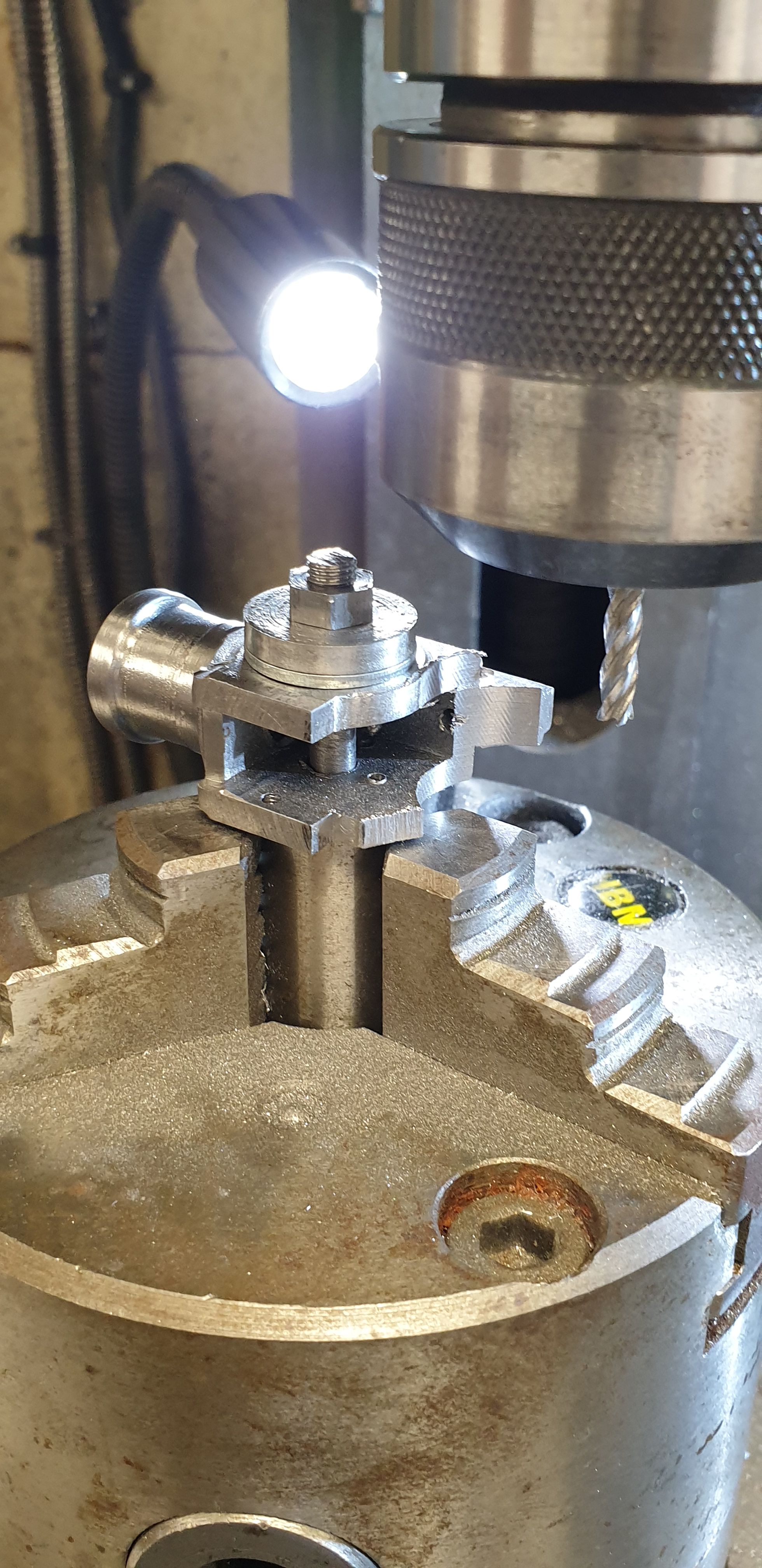
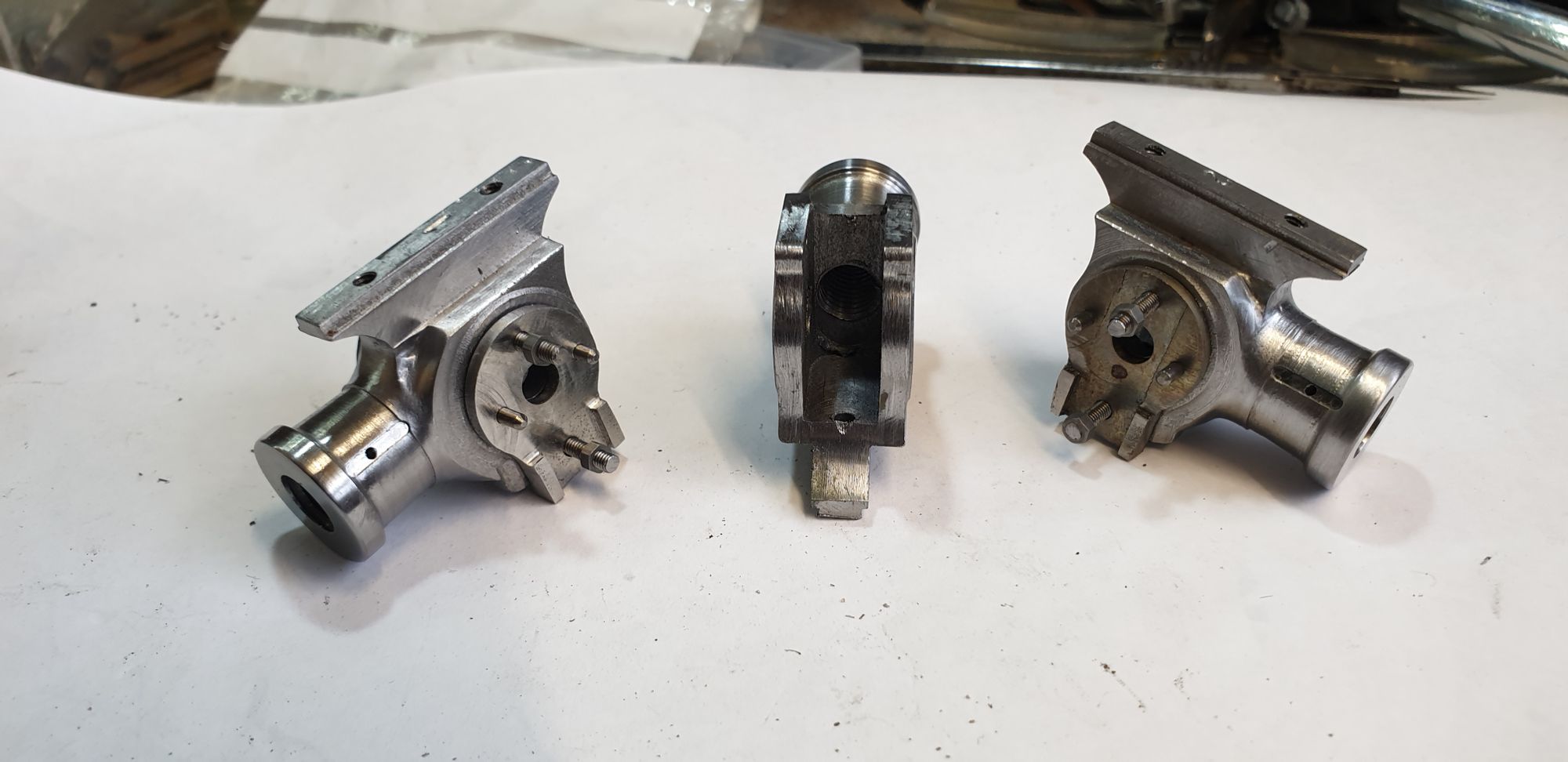
back to the rotary table for the very last machining set-up, the final operation being to machine the rear curve around the raised collar. I have no idea how many set-up's were involved on these crossheads, it was many, this is the last...hooray. Well it will be when I have done the other face as you can see in the picture, I used a hacksaw to remove most of the remaining material.
After yet more hours of hand filing, grinding and polishing I now had 3 crosshead body's ready for the next stage
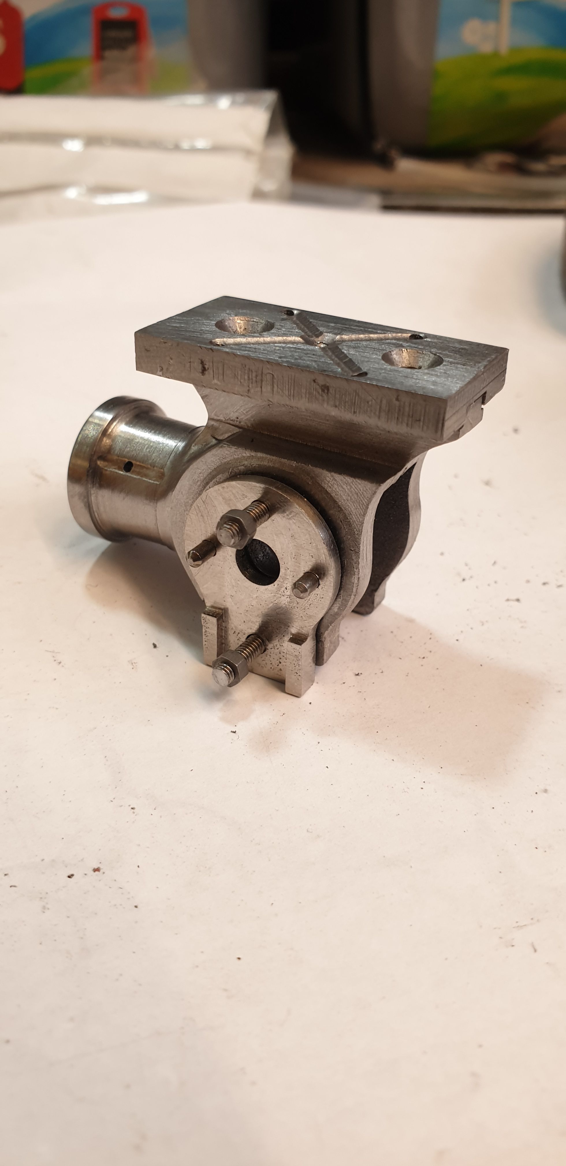
That next stage involved hammering in the 3/32 dowels after first cutting off their tails so as not to impede on the connecting rod. These are a very good fit and the mounting plate requires a slight tap to locate properly which is good as there is no play at all and the mounts are square to the slide bar. also added is the 8BA studs to bolt down the drop link when made, currently I have left them slightly overlength and not secured with Loctite yet.
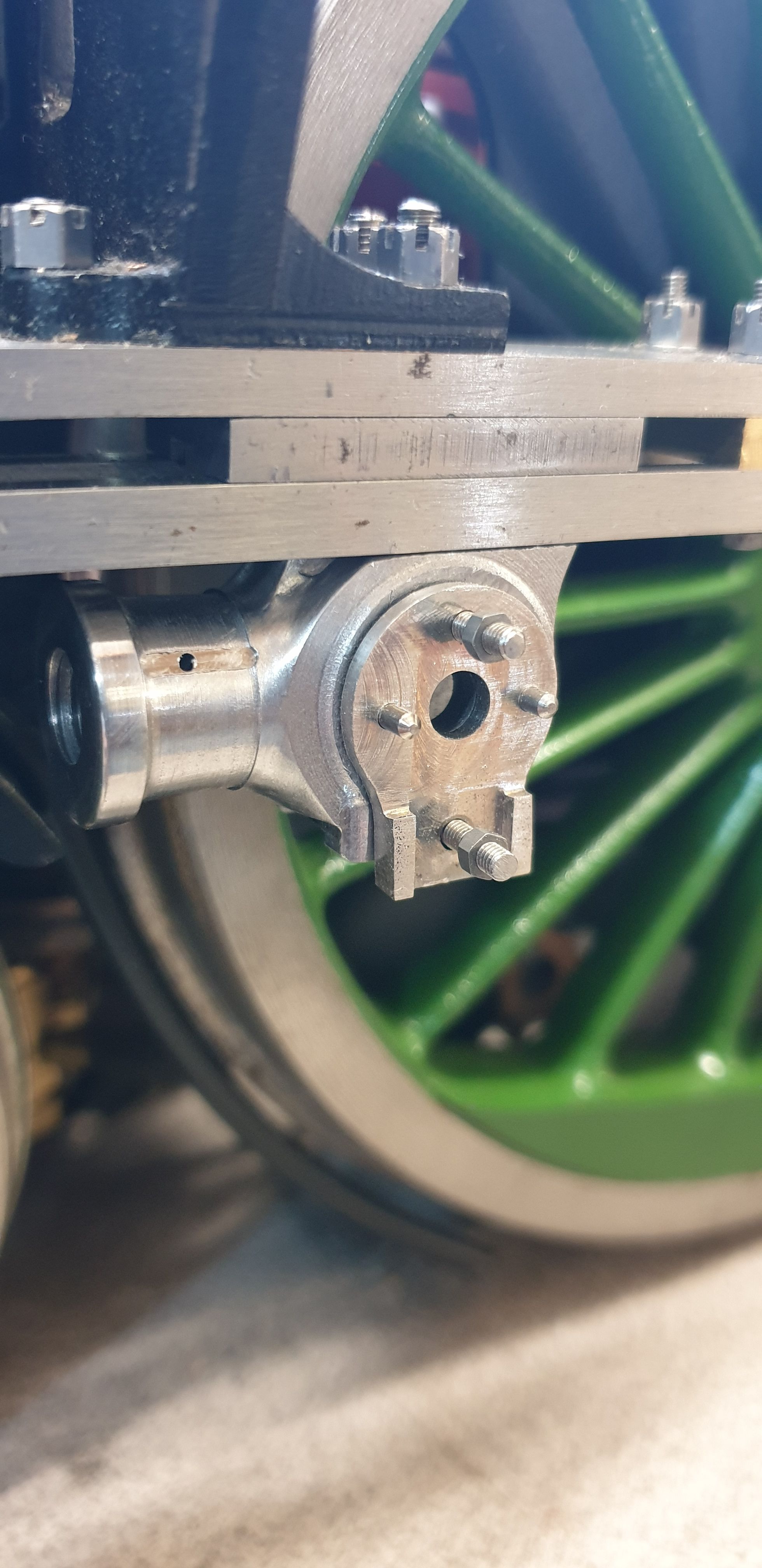
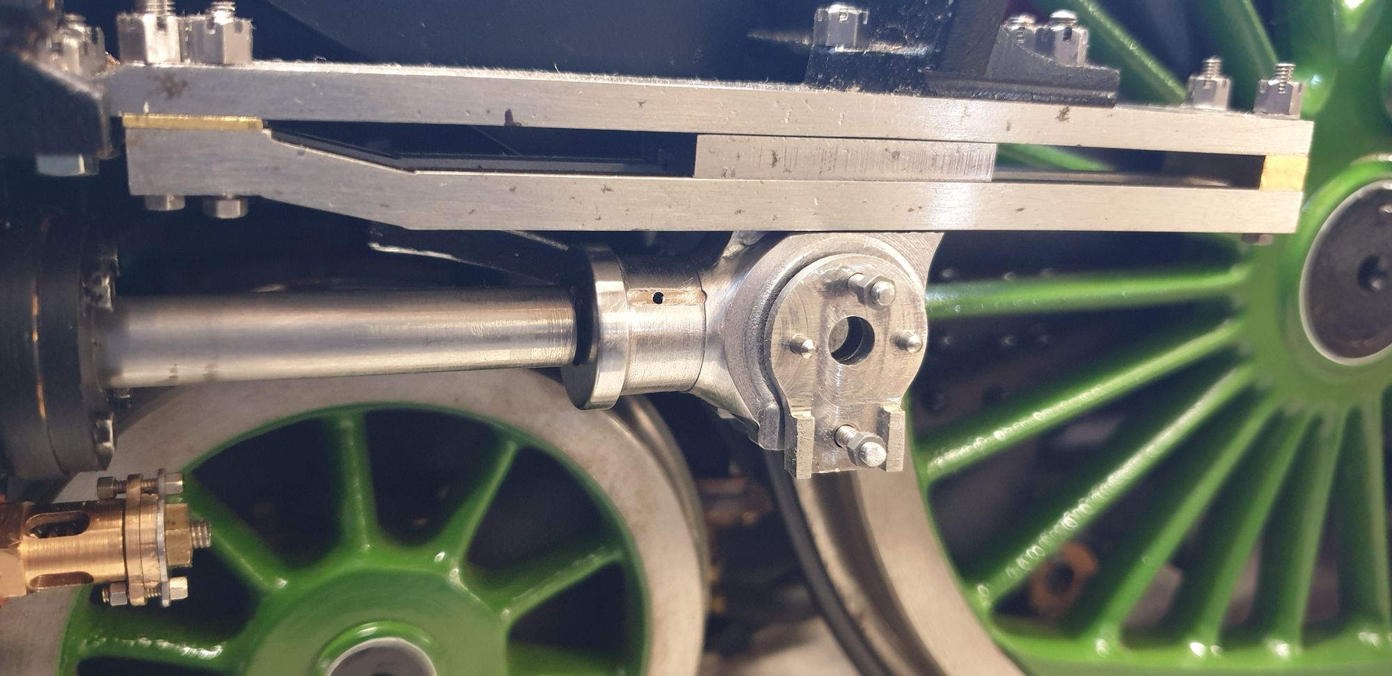
A couple of pictures after the final (I hope) polish, the crosshead from the rear with its slipper placed in situ.
And of course, a picture with one of the crossheads on its slide bar. It will be sometime yet before these are permanently fitted, I need to make the outside couple rods first. Before that I need to make the gudgeon pins, oil reservoir and drop links.. I best get a move on then..:) Oh and in posting this picture I notice that I haven't finished yet, I still need to round off the top edge of the sides.:)