
Today we see the crossheads finally take their shape at the front end, I won't say just how many hours this took to achieve, it was a lot. Last time I covered the machining, this time it was all hand work, beginning with the Dremel, using diamond grinding tips and then needle files to smooth the surface. Next it was back to the Dremel, although this time using W&D sanding disks which give a lovely polished finish, but also, they are abrasive enough to do the final small areas of profiling. I have kindly been sent a good few drawings/pictures of research material to help in this part for which I am most grateful. One thing that was clear is that no two crossheads were the same, I'm not talking about the various designs, no more how they were machined and I guess their maintenance during a long main line career. Also the cotter slots seem to vary in their position, some cut into the front ring while others cut into the rear area. I did notice here that my recessed area in the taper could do with being a little longer, I'll decided whether it's worth doing this or not later, might be prudent to leave well alone at this stage.
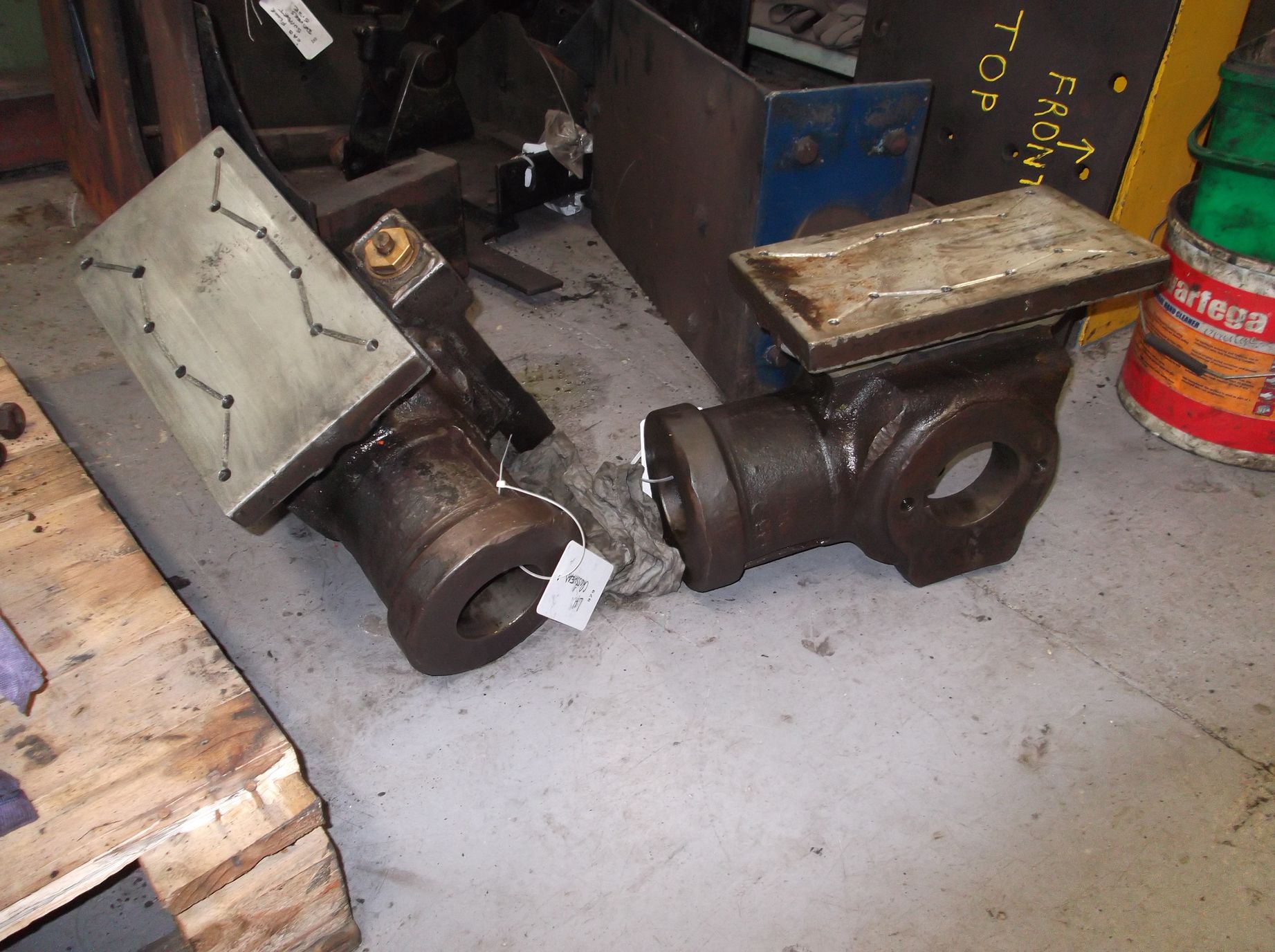
Ok, so on to the work done, I'll begin with showing a picture found on the web showing SNG's crosshead during her current overhaul. I do have a few from the current overhaul including some that I hadn't seen before sent to me by a fellow model engineer.
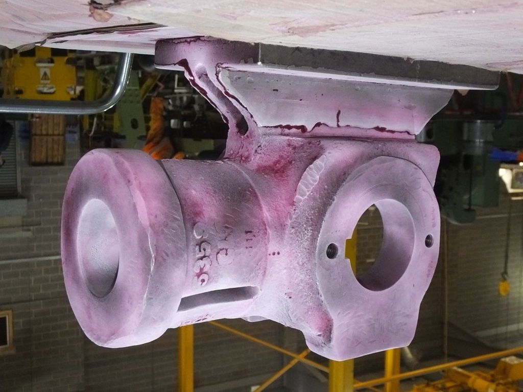
An inverted closer image of the same crosshead which was kindly sent to me recently.
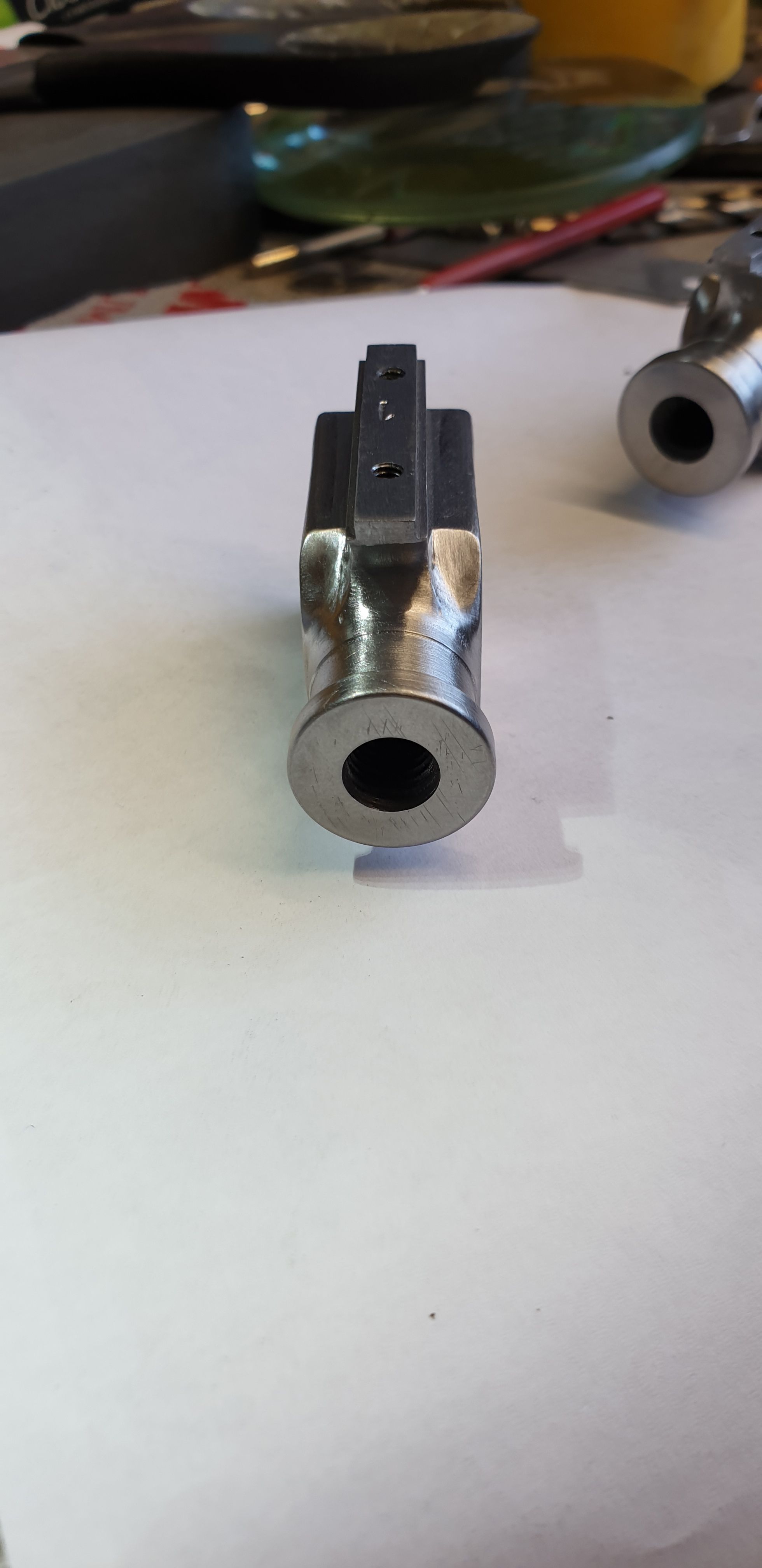
Here we have the model so far, not there yet but getting closer. A few things to point out, the raised area where the gudgeon pin enters seen in the picture above is still to be machined. I will machine this as a slight relief on the side letting the mounting plate bring it out closer to the prototype which may be what Don intended, I'll explain this later below. Also the rear still has to be shaped, a lot of the rear area seen gets removed.
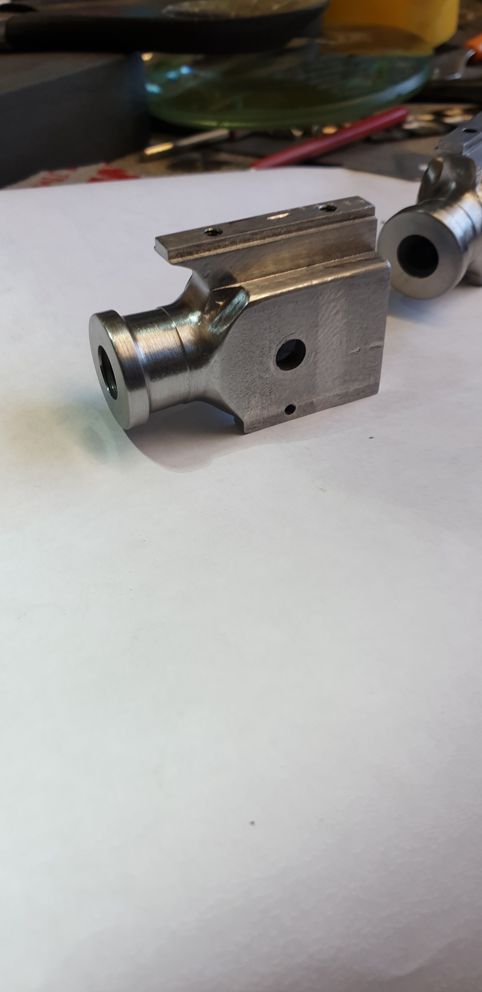
A view of the model from the front which gives a better idea of the overall shape, the crazy thing is that once fitted to the slide bar most of this detail is hidden, at least I know it's there..:)
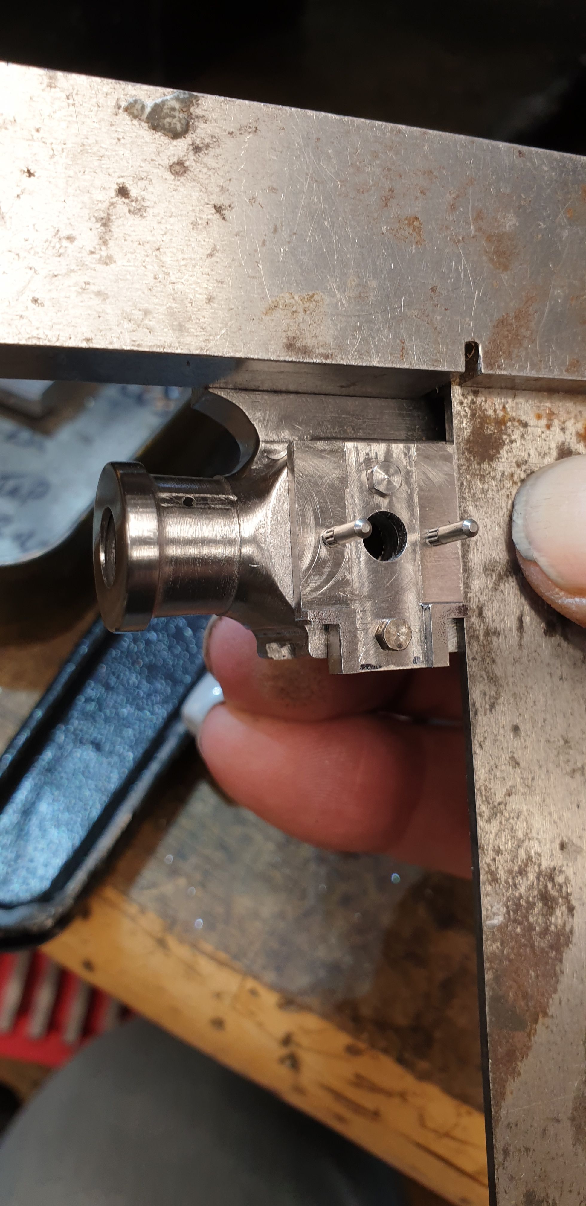
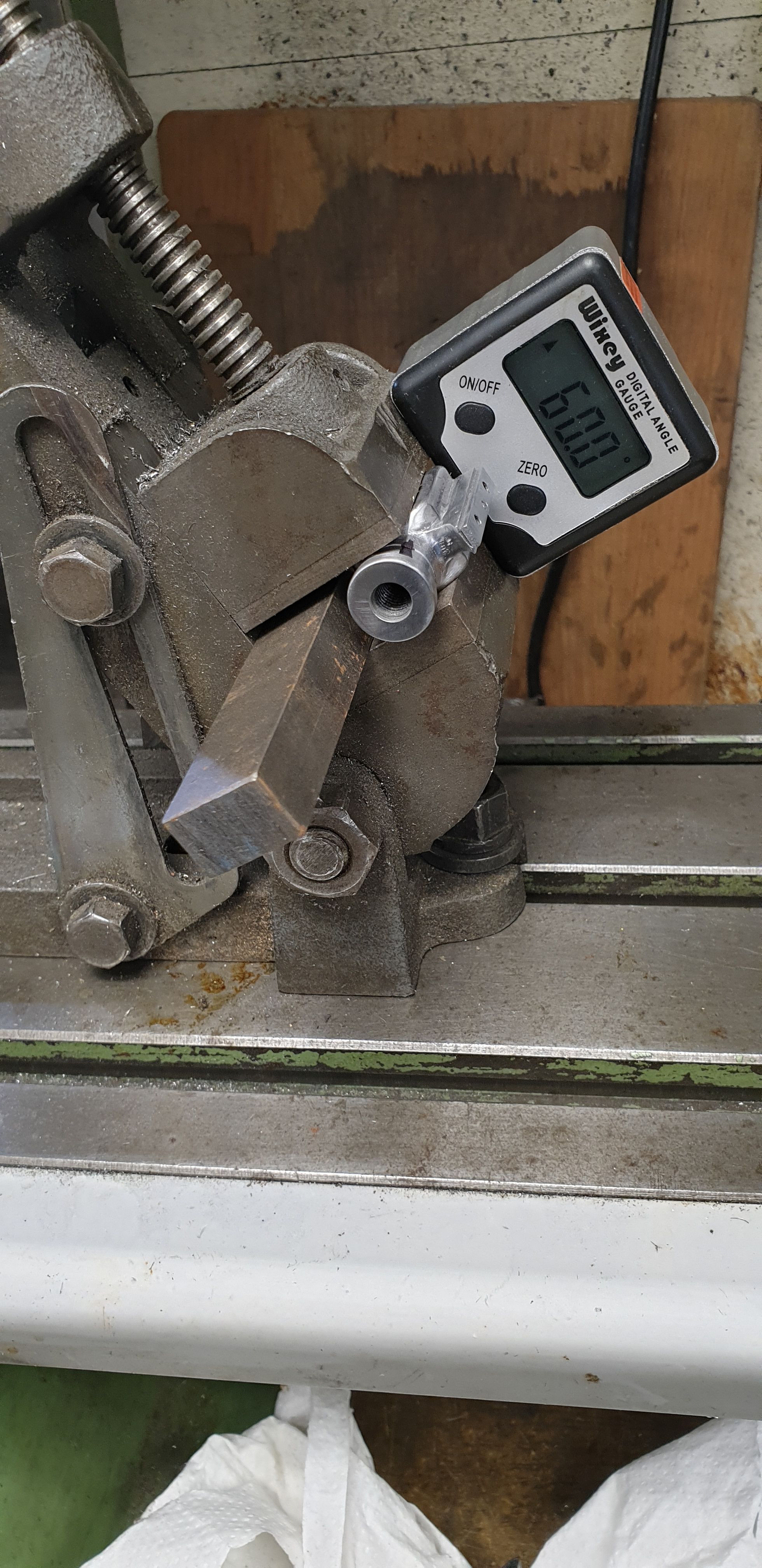
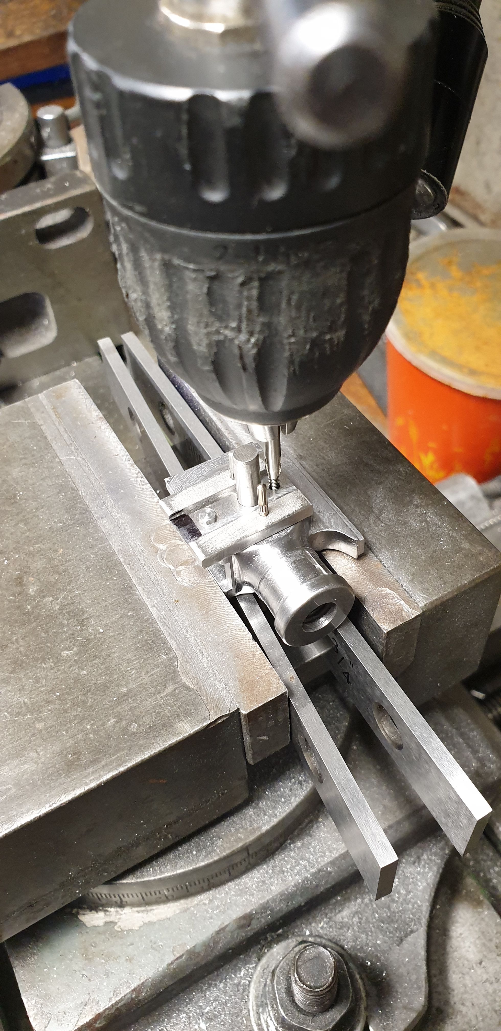
Before I can move on to the rear profile I first needed to drill/machine the slot for the dummy cotter pin. Why a dummy? well it's easier to make and the piston rod itself is held by its thread and the locking grub screw at the rear. This meant that one, I could make a dummy and two that I could use a smaller taper pin at 1/16 rather than Don's 1/8, in fact he states to fit two. Using the smaller pin means that I can machine the slot to scale (11/16 full size) and the pin can go straight through the dummy cotter and filed down so that it disappears, more on that later. The picture shows the tilting vice being set at 60 degrees to give the correct slot position of 30 degrees up from the horizontal. Don't worry about the smaller pin, it isn't holding the piston rod, the rod is held by the 5/16 BSF thread and locking grub screw. Look at the pin is a fail safe.
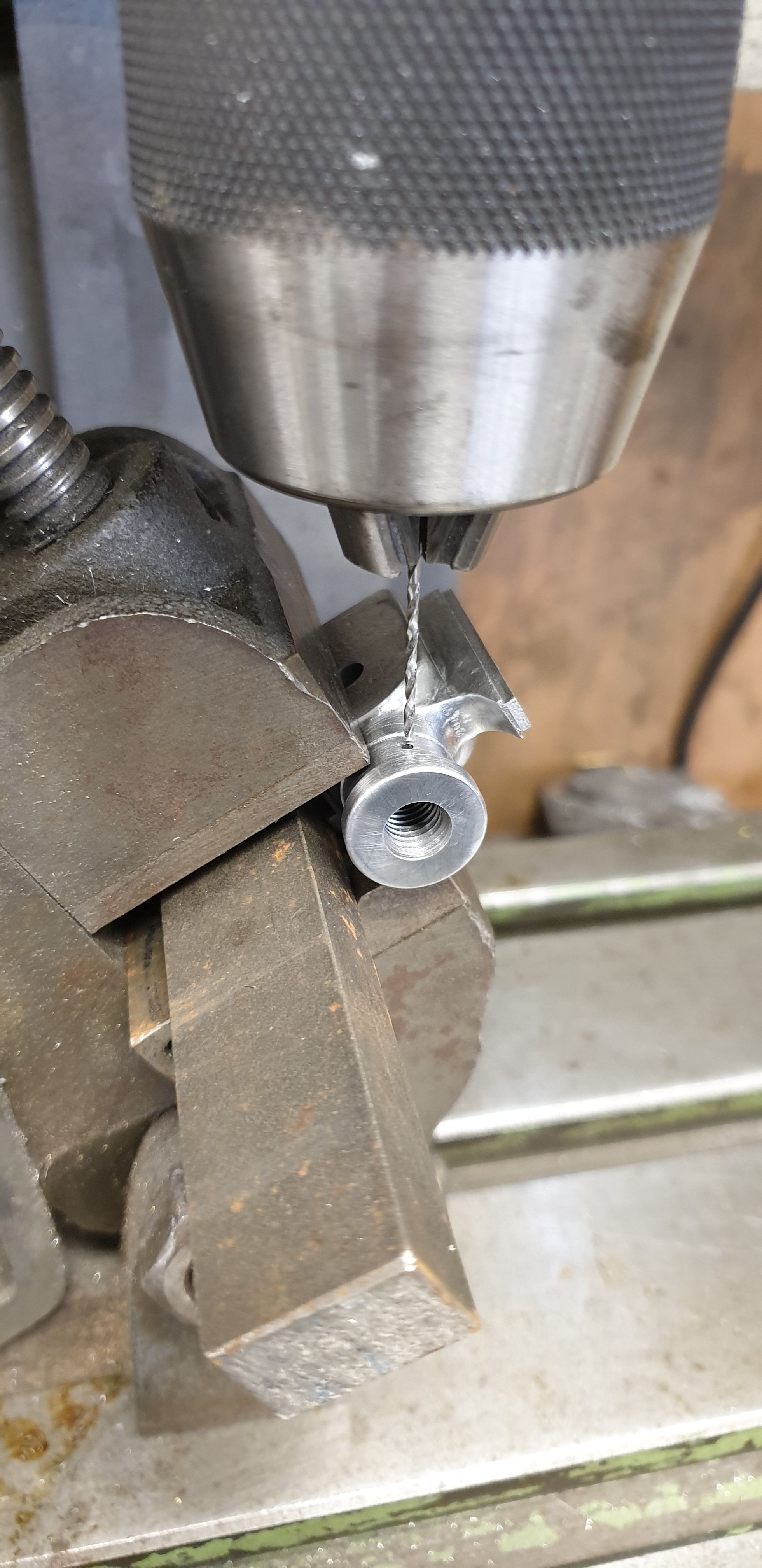
After centering the hole it was drilled using a 0.053 drill bit which is close to the smaller dia of the taper pin. I have only drilled through the one side of the crosshead, I'll drill right through and then taper the hole once the piston rod has been fitted, this removes any possibility of the small drill deflecting a little and then missing the center of the hole below. I should have taken another picture showing the slot, I forgot to take that one.
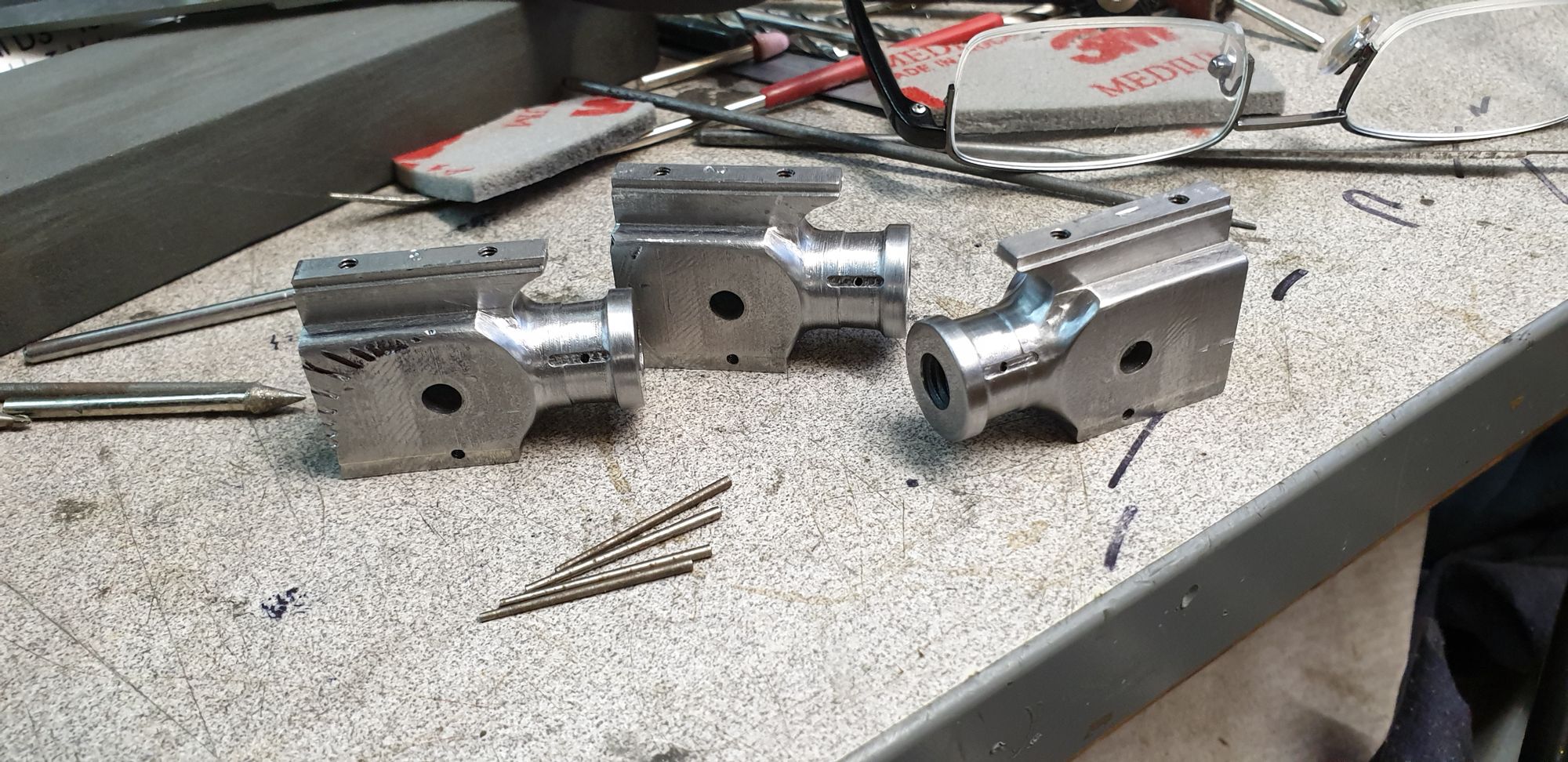
Here we have the three crossheads having had their slots machined to a depth of 10 thou, just enough for the dummy cotter to rest in. I will also hold my hand up to a mishap which I'm sure you can see, this was me not tightening the vice properly when setting up to machine a small chamfer along the top edge ready for being rounded of by file, I simply forgot to do the vice up...lol
No real harm done as most of this damage will be removed when the rear is profiled and the rest is mostly under the drop link mounting plate, you see, even I make mistakes and will show them when I do...:) I also at this stage decided that the recessed step being shorter than it should be just wouldn't do and so I reset each crosshead up in the 4 jaw to machine the recess a little more, this will become clear in a few photo's time.
The next job was to get the sides to profile, I took a little off on the rotary table to give me some idea of what's what for the rear shape but before doing any more I thought it best to make the drop link mounting plates first. I began with marking these out on some stainless steel flat bar that was 120 thou thick. The next picture shows the relevant holes drilled after first sizing and squaring off the blanks, I'll explain these as they are a mix of Don's 'Doncaster' drawing and also of Eddie's works drawing for the 1934 pattern. Ok, so on Don's drawing there are only the two holes, the main hole for the gudgeon pin and the lower hole (at 0.375 centre's) for the 8BA hole (Don states 7Ba) that help line up the drop link. Eddie's drawing also includes a further top 8BA threaded hole for the earlier drop link and also two holes either side of the gudgeon pin at 0.454 PCD. These are for 3/32 (scaled) dowel pins. This is how the 1934 drop link is held secure to the crosshead. The later drop link as fitted to FS today relies on the gudgeon pin and lower smaller bolt and then reinforced with welds down either side of the drop link. The 1934 pattern is held within two lugs as well as the studs and dowels, this will become clearer as we proceed. If you look closely you'll see that both mounting plates were drilled together. BTW, I say bolts, these will be replaced with 'studs' later.
I included this picture to show the two plates separated and also a dowel tried for size. These hardened pins have a splined section in their middle. I will remove the plain shaft from one end so that the spline will be drifted into the crosshead leaving a plain section for the mounting plate to locate on, this will become clearer later too.
I then returned the plates together in the machine vice but this time next to each other along the 'X' axis and machined a slot along their length leaving the metal with a thickness of 62 thou. I didn't take a picture of this stage but the slot can be seen in the next picture. This slot when the mount is finished will leave the two small tabs that are at the bottom of the mounting plate that help keep the drop link vertical.
Before I could remove the upper area to match the 62 thou thickness above the tabs, I dry fitted the parts to their respective crossheads ready to transfer the 3 new holes in each crosshead. My reasoning being that it's better to transfer the holes through the plate while still 120 thou thick than when only 62 thou thick. A word on this 62 thou dimension, Eddie's work drawing's scaled dimensions shows this as 55 thou, I have kept mine at Don's dimension of 62 thou to ensure that the union link runs parallel when connected to the combination lever. Just one of the many things that needs to be taken into consideration when working with both a model design and works dimensions. This picture also shows that I have increased the length of the recessed step on the taper. I had a heart breaking moment when machining the last crosshead as one of the lathe V belts decided to shred itself making the lathe jump as the motor dropped. All I can say is that I'm glad that this old Warco is so heavy/rigid as the tool didn't move at all while I was making the final pass, sometimes I just get lucky..:)
Ok, with the lathe down until new belts arrive I couldn't turn up a new button for the crosshead side faces and the mounting plate circular section. So I have done everything that I could do to the mounting plate for now.
First up was to transfer the mounting plate holes to the side face of the crossheads. With the lower 8BA hole already drilled/tapped on the crosshead, using a suitably sizes length of silver steel I could line up the mounting plate blank ready for transferring the holes. As stated numerous times I try to keep square faces for as long as possible, here it made life very easy to ensure that the mounting plate is vertical when bolted to the crosshead. Once checked with a square. I started by drilling the two holes for the dowels.
Once those were done with the pins pushed lightly in place I drilled /tapped the top 8BA hole.
I then finished machining the front face of the mounting plate which is flush with the slot. Next up was to machine the outer edges of the locating tabs for the drop link. The last picture shows one of the plates mounted to it's crosshead, in this case it's the L/H outside cylinder. I only need to machine the circle to blend in with the bottom vertical section and a little filing of the tabs to complete the mounting plates. I have tried to angle it to show the face of the plate to give an idea of where I am heading. Also you should get some idea of where I'm going with the side face, the flat section to the front of the mounting plate will be machined using a ball nose cutter, referring to the full size photo's shown above should give an idea of what I need to do.
