With the outside connecting rods and pistons now fitted and working in their cylinders, it was time to do the same for the middle cylinder. The connecting rod itself was made some time ago but I still had the big end brass to do and thus will describe my approach in machining this spilt bearing here.
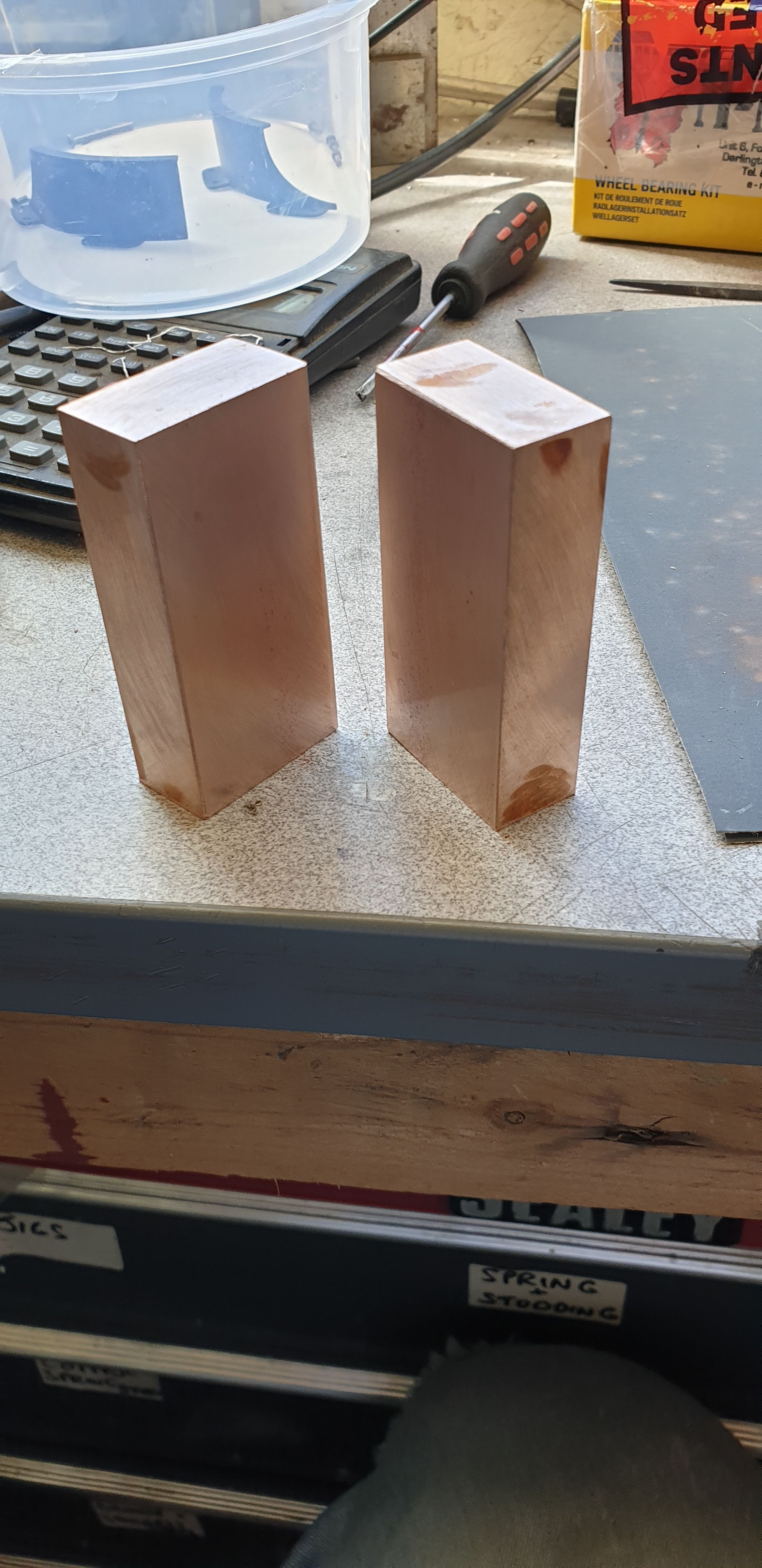
As it's a split bearing I begin with two flat blocks of bronze, it was difficult to find the size bronze bar that i required so I have used (IIRC)a 5" length of 1 1/2" square bronze which was bought from M-Machine-Metals who also cut it in half for me, not having anything myself to do this.
Here's the two sections, I then polished two of the wide faces flat and bonded them together with Loctite 638.
The resulting block was then machined square ready for holding in the 4 jaw chuck. Using my smallest center drill which is a special that my son gave me, seems smaller than a standard no.1 and with a much longer tip. Due to this tip it was easier for me to see and line up with the split in the block and also the middle line marked.
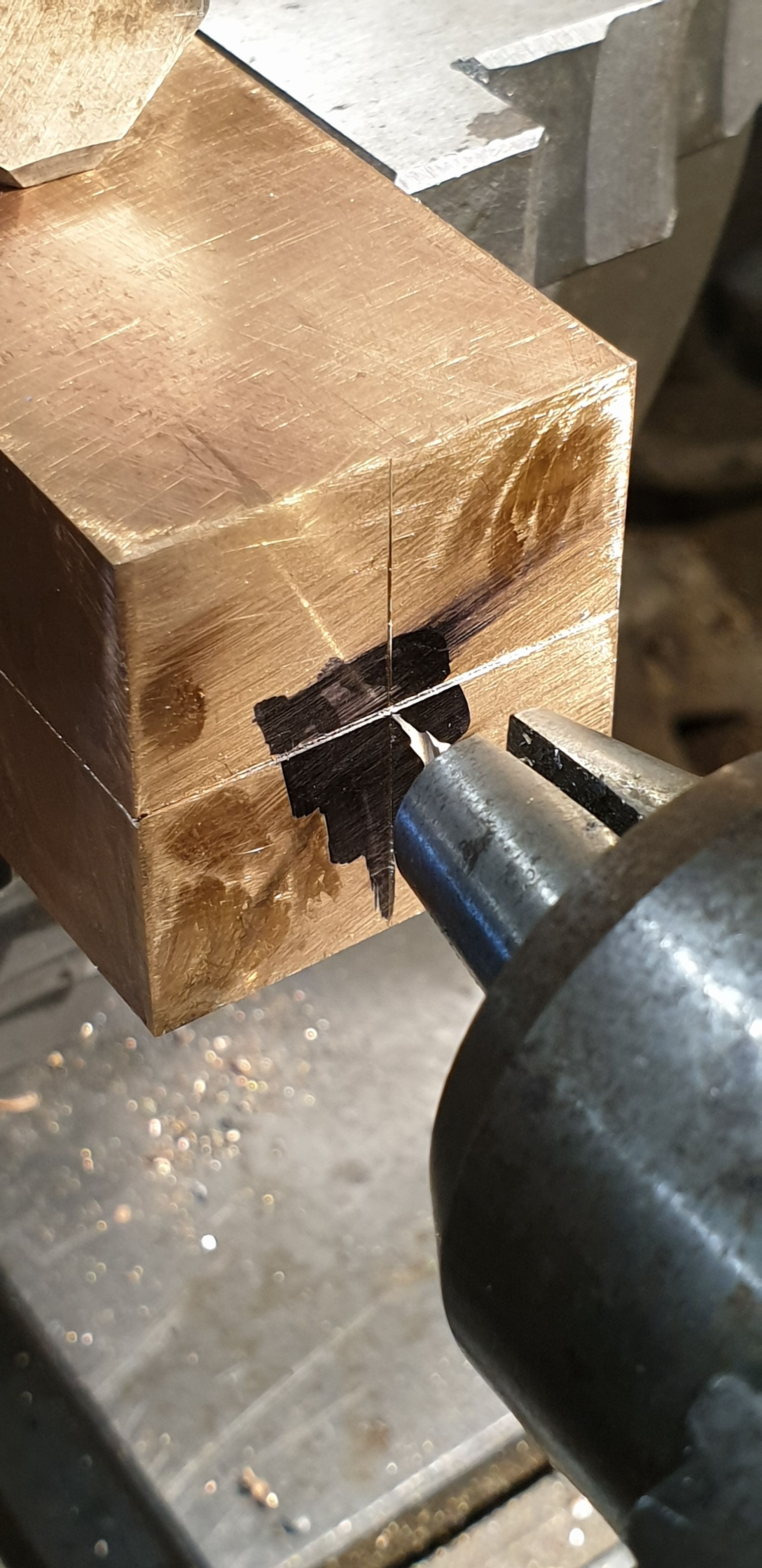
Once I was happy with the centre, I then made a small mark and faced the end off.
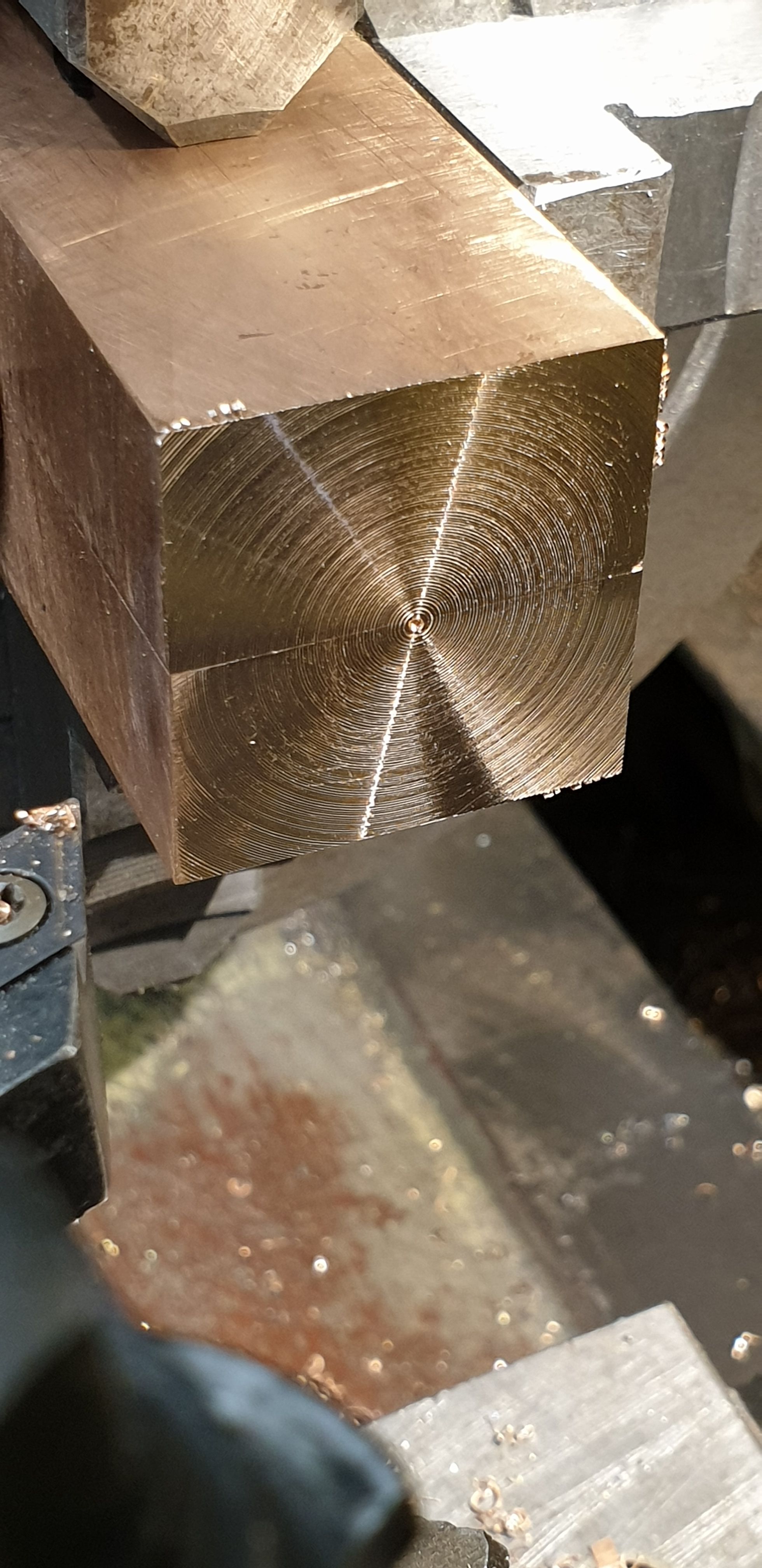
Next, I turned down the bar for more than I required in length, (to give better clearance later) and then turned down a further section to the required 1 1/8 dia
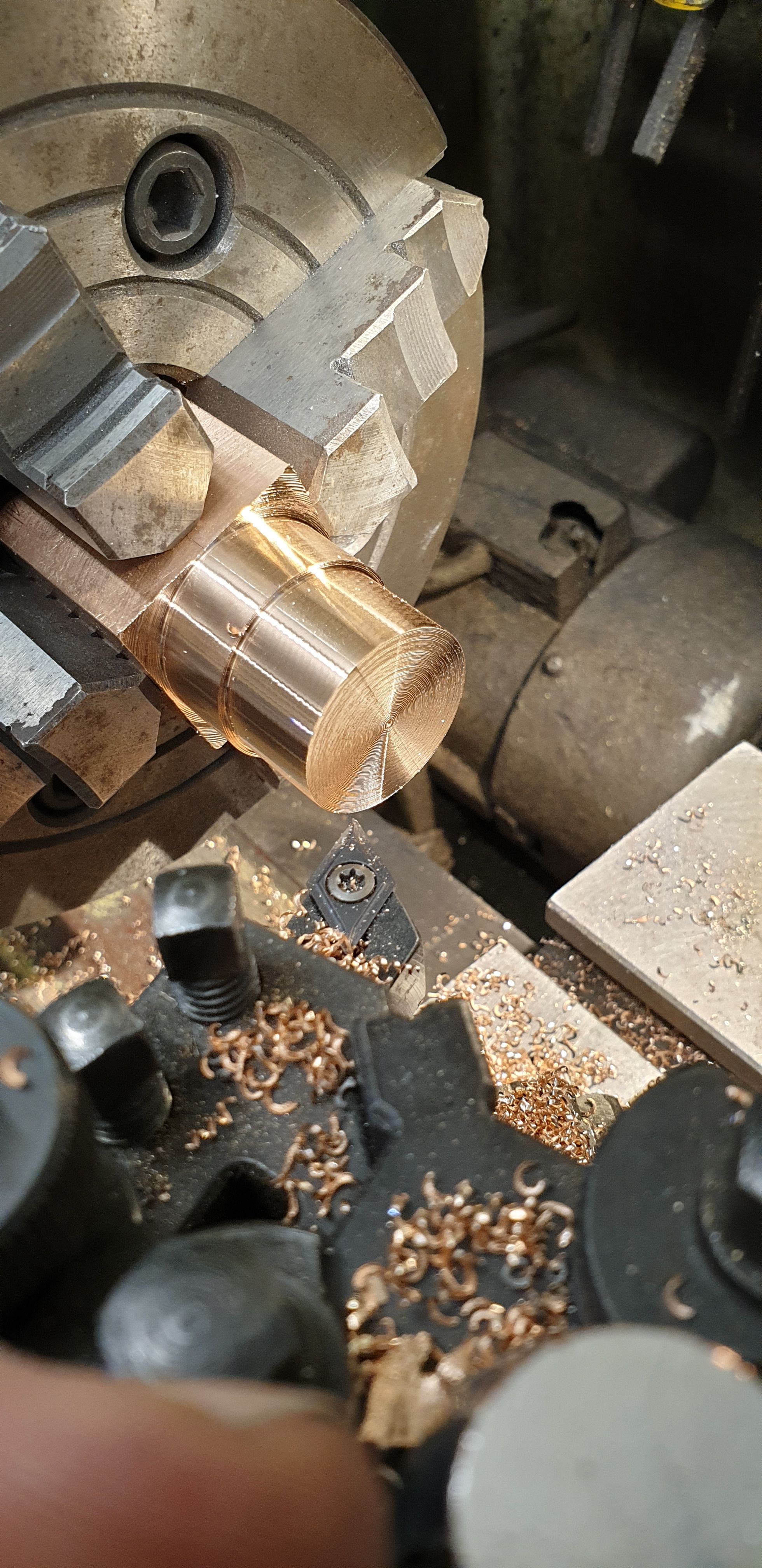
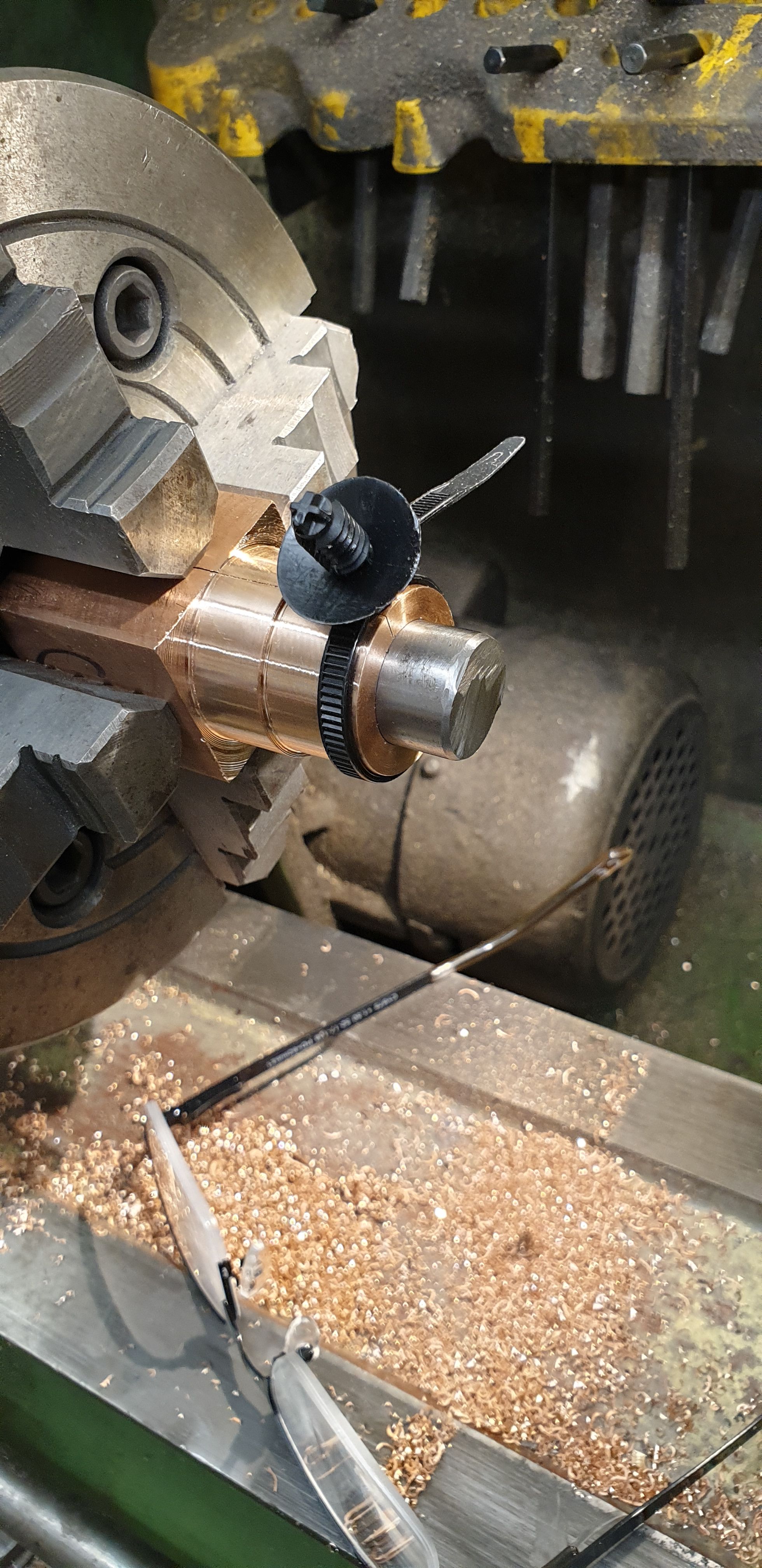
I then bored the blank to the required 3/4", this was done with a number of step drills out to 11/16 and then finished with a boring bar until an offcut left over from the crank material was a good sliding fit in the bore. The cable tie was used to unsure of no movement due to heat for this process.
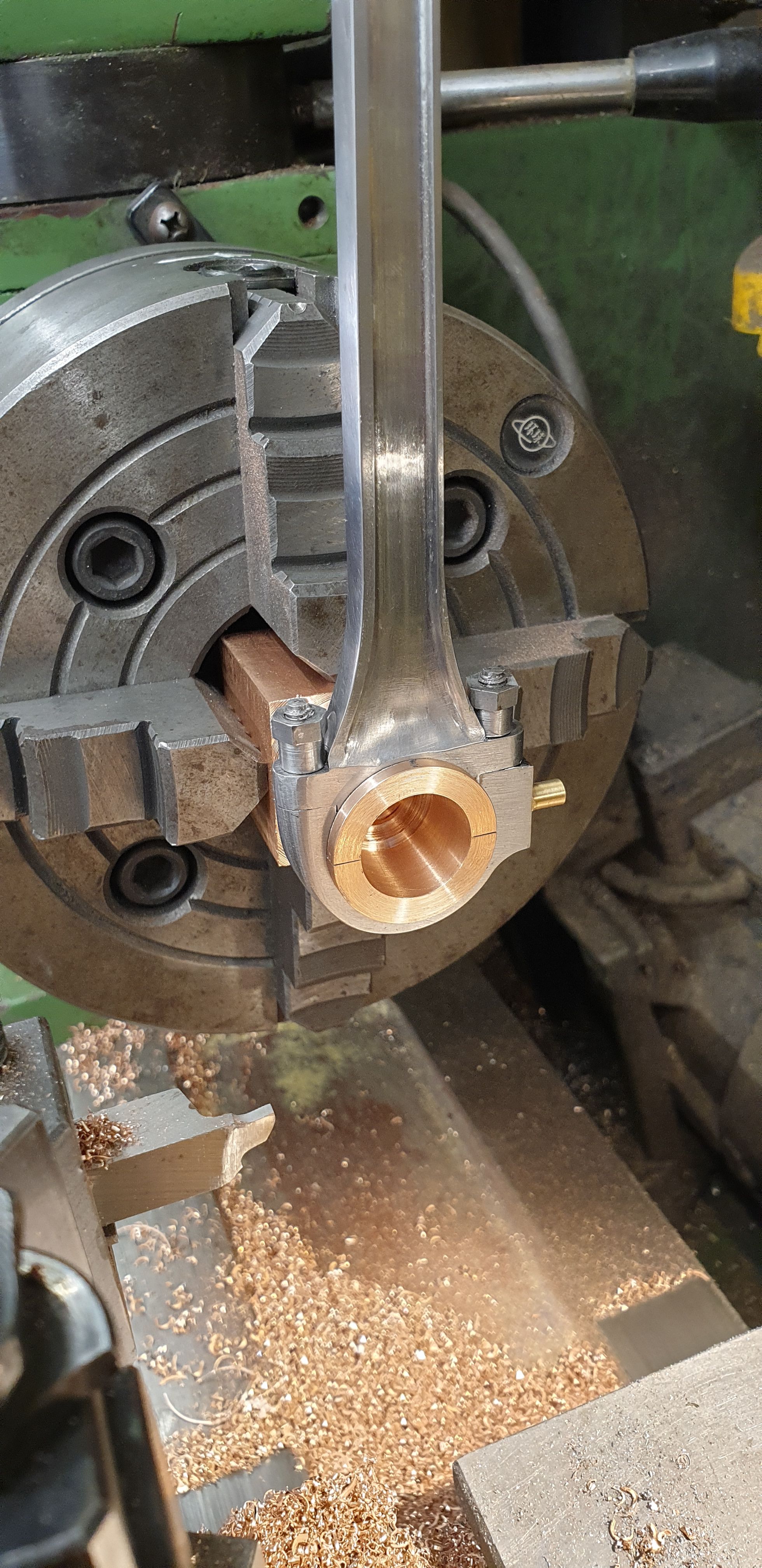
Now I seem to have missed a few pictures, very important pictures but I guess I was a little preoccupied in the machining of the important recess to fit the connecting rod and it's strap, so please forgive me for this omission. The picture shows the end result but I'll say what I did. First was to note that the bush is 'offset', this is due to the middle cylinder not being exactly in the middle, IIRC it's offset by 1/16? Don's drawing shows the side flanges to be 0.120 wide on one side and 0.090 on the other with a small step on each. This was noted and machining was done using a narrow HSS ground tip which was re-sharpened a number of times, the bronze being very tough. The recess was machined to be a good fit for the width of the rod and strap and was deepened gradually with regular checks on the fit of the rod and strap bolted together. I did this until I had a very good fit of the rod while also checking that the crank offcut wasn't being pinched in any way.
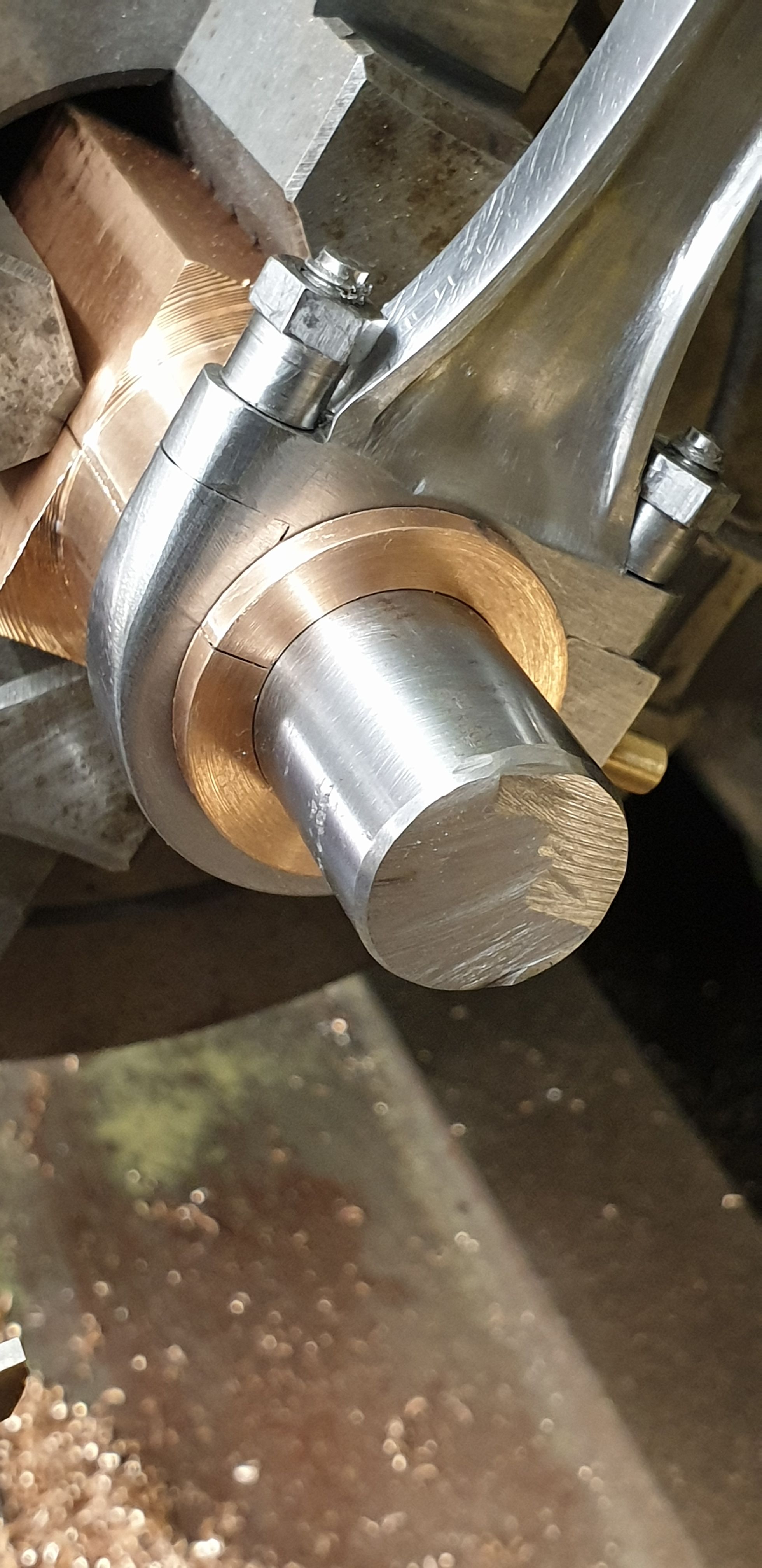
I final check was done on the fitting of the offcut from crank material which at this stage is a tight fit, I'll ream the assembled brass/rod to 3/4" later.
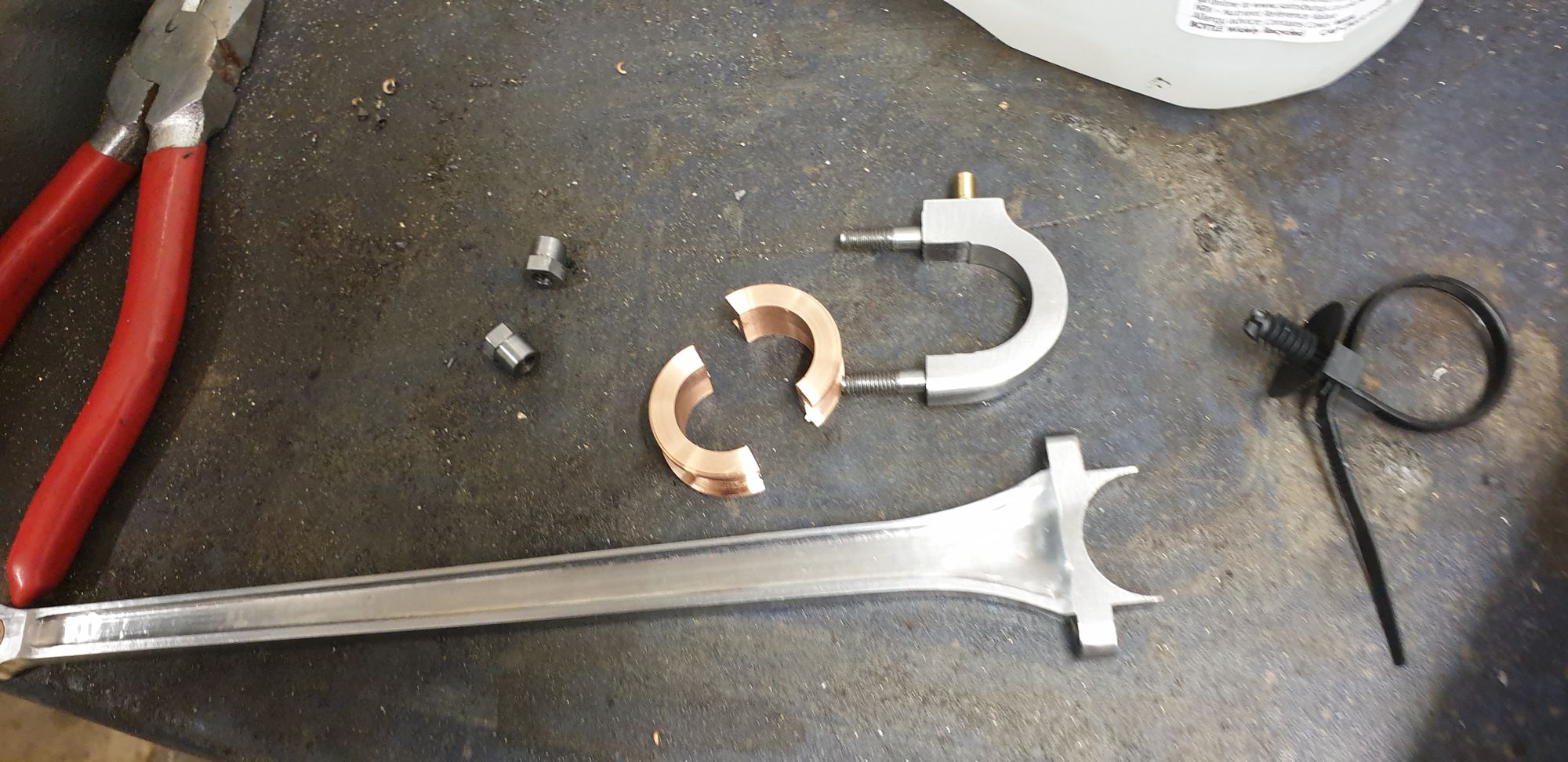
Once happy with the fit and width of the bearing I then parted it off, the various parts are seen here. The width may need a little fettling due to the paint on the crank but if so it won't be much.
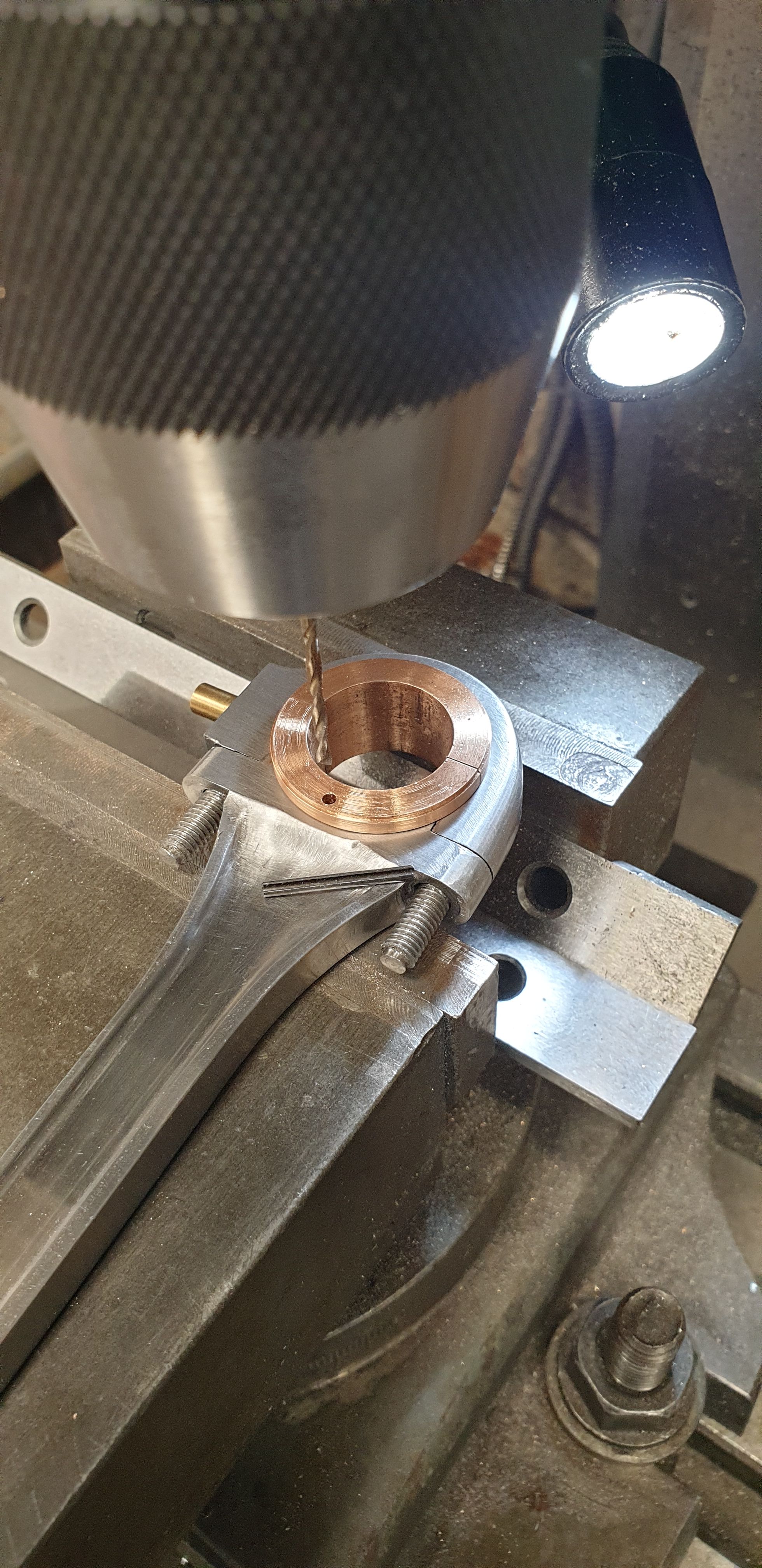
I'm getting closer to being able to fit this connecting rod now, the next job was to cross-drill the brass to fit a roll pin to ensure that the brass can not turn during service resulting in a seized bearing from lack of oil. I decided to use a roll pin as it would be secure in the rod with no chance of it working loose. I chose a 1.6mm roll pin, drilled one half of the brass first, clocking it to be central and then placed this brass into the rod and transferred the 1.6mm hole. I decided to open this out to 1.7 so that it would be easier to remove at some point in the future. I wasn't expecting that point to be a few minutes later when test fitting the rod only to find that I had fitted the brass the wrong way around. That is, the wider flange to keep it central with the cylinder was on the wrong side...lol I was very glad at this point that one, I had made the pin easier to remove and two that I had taken the extra time (not important if you fit the brass the right way around to begin with) in centralising the hole in the first place. I have laid the pin on the rod for show, it was cut to be under length by 20 thou to ensure that it didn't stick out proud.
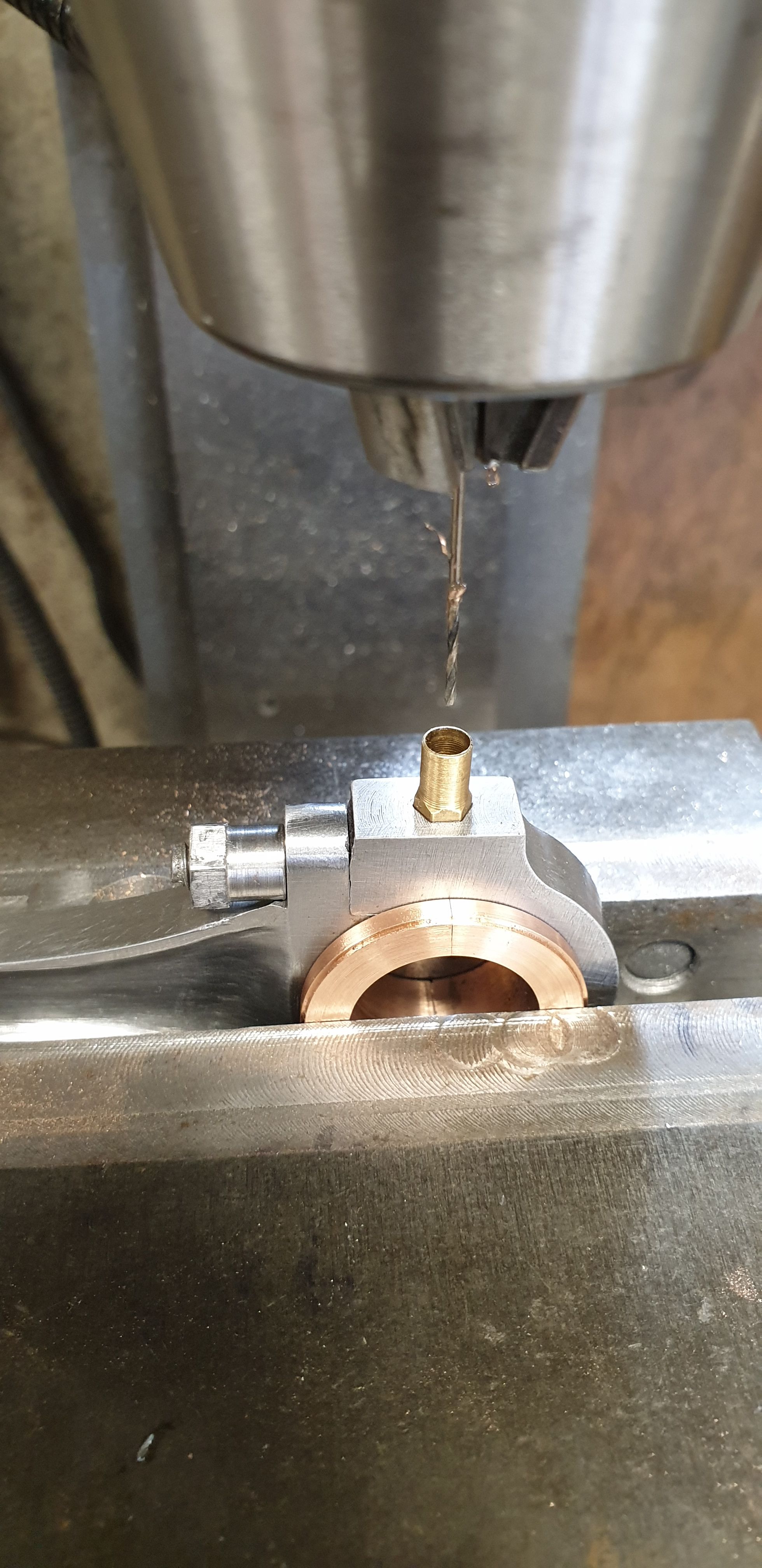
I then drilled the small oilway through the brass. Just to point out, they are not brass, they are bronze but are I believe called 'brasses'.
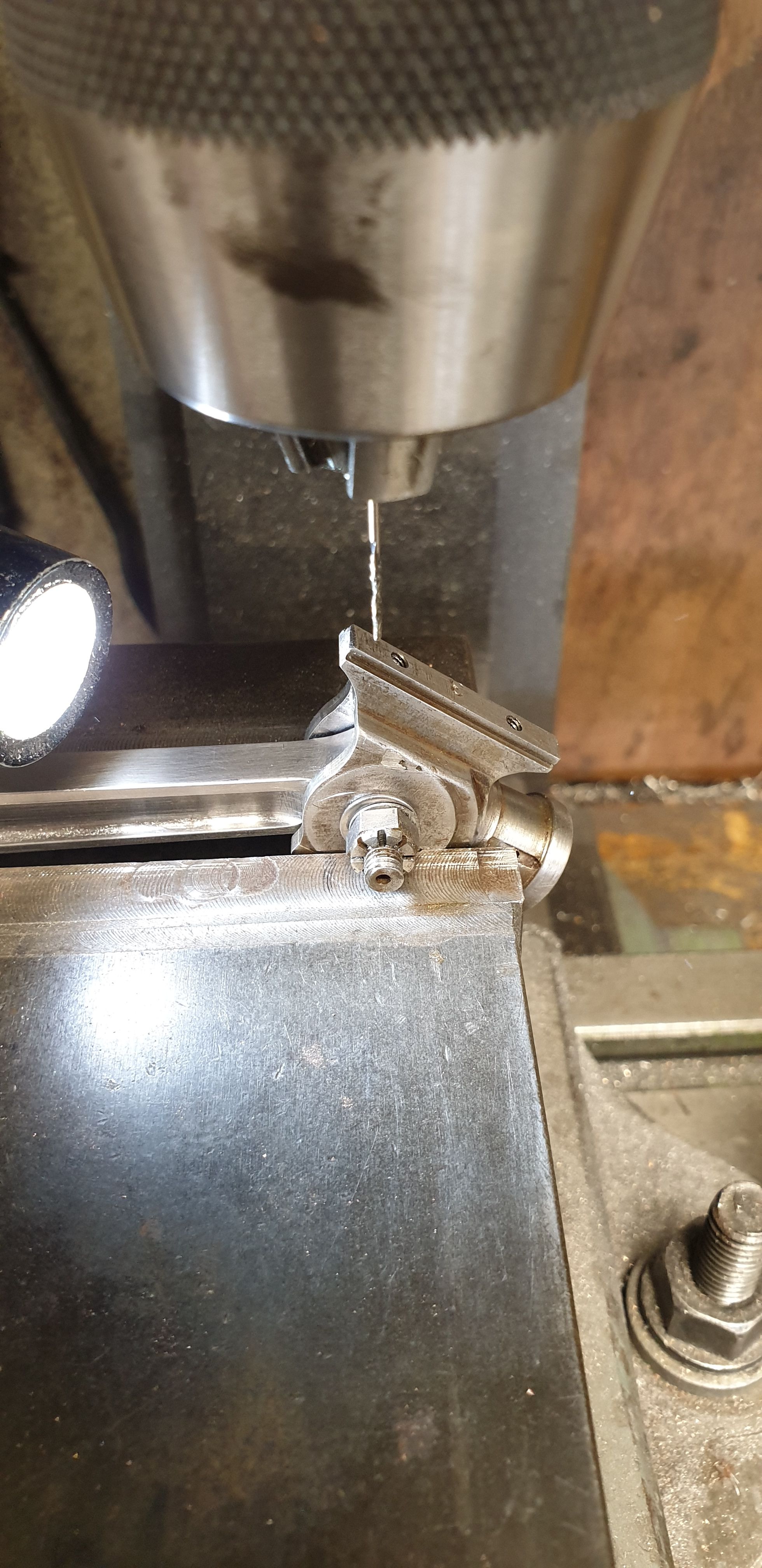
Another job to do before fitting (still need to do this to the outside rods) was to crossdrill the gudgeon pin for the split pin to trap the castellated nut. The spilt pins are 1/32 but instead of drilling to that size I have drilled the hole 0.092 to allow room for the oil to pass through.
Here we see the assembled rod with crosshead ready to be fitted, at this stage I still needed to do a final pass with a 3/4" reamer which was due to arrive the next day, so this is where I got to that day. I did also test the piston rod for length, shortened it and threaded it to fit the crosshead.
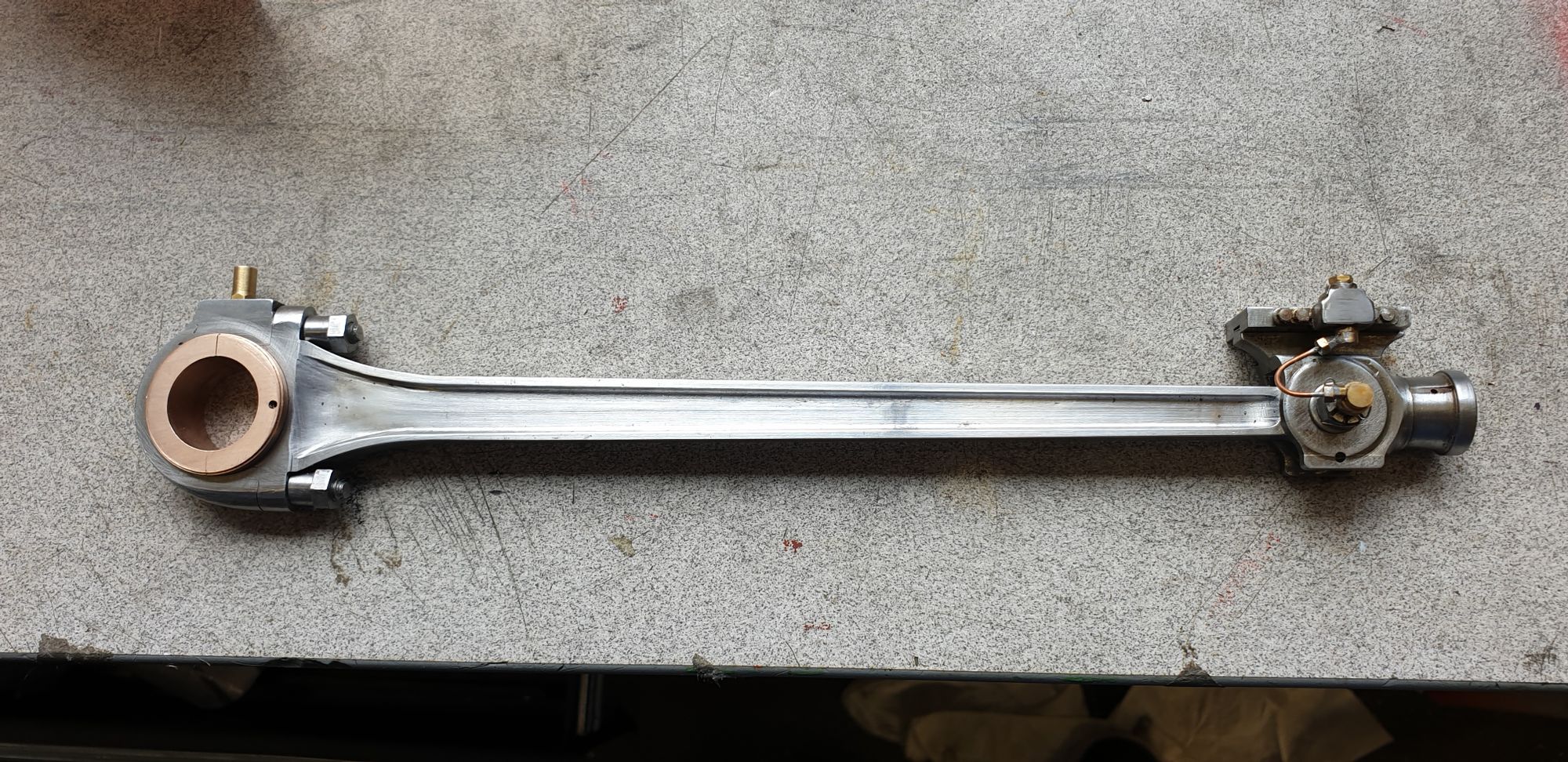
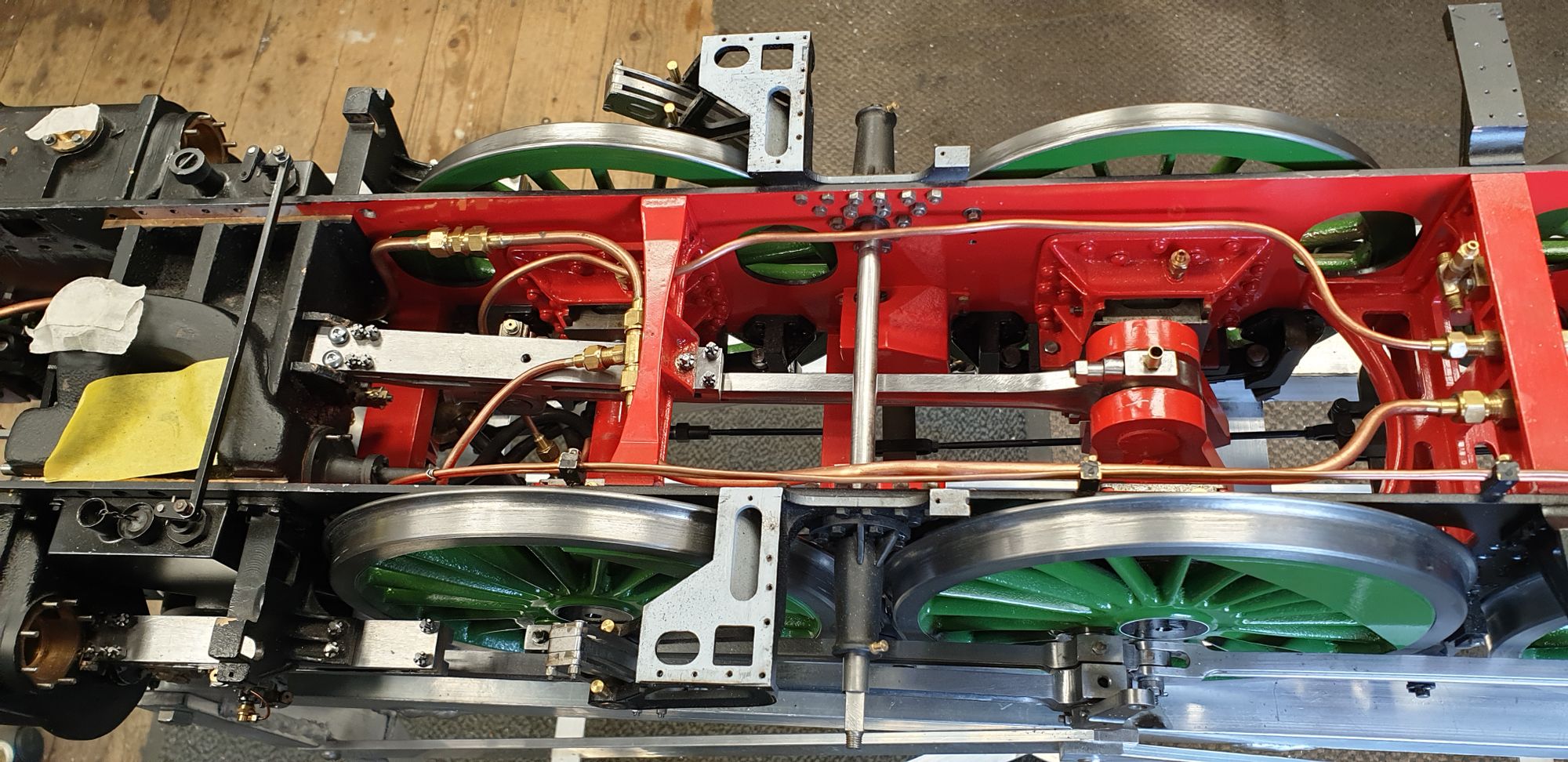
Last picture for this entry shows the inside connecting rod now where it belongs. Next week I'll make a start on some tidying up jobs, this will include making all of the oil pots in Bronze, fit new cork stoppers that this time if all goes to plan they will be actual cork rather than the current tooth pick material. This will include the oil pots for the slide bars for which I plan to follow the older design than I suspect was on the loco in 1938?, it's basically the same as fitted to the loco and the A4's on the middle cylinder today which is testimony to it being a good form of lubrication. I'll also do a little touch up of the paintwork in those areas which will soon be impossible to get at and check that the vacuum piping is fully sealed while still accessible. I'll also make up the steam pipes for the steam sanders, these will be the second batch, I wasn't happy with the first and have decided to remake them with a slightly larger bored copper pipe.