
I have a fair bit to cover in this entry, so here goes...
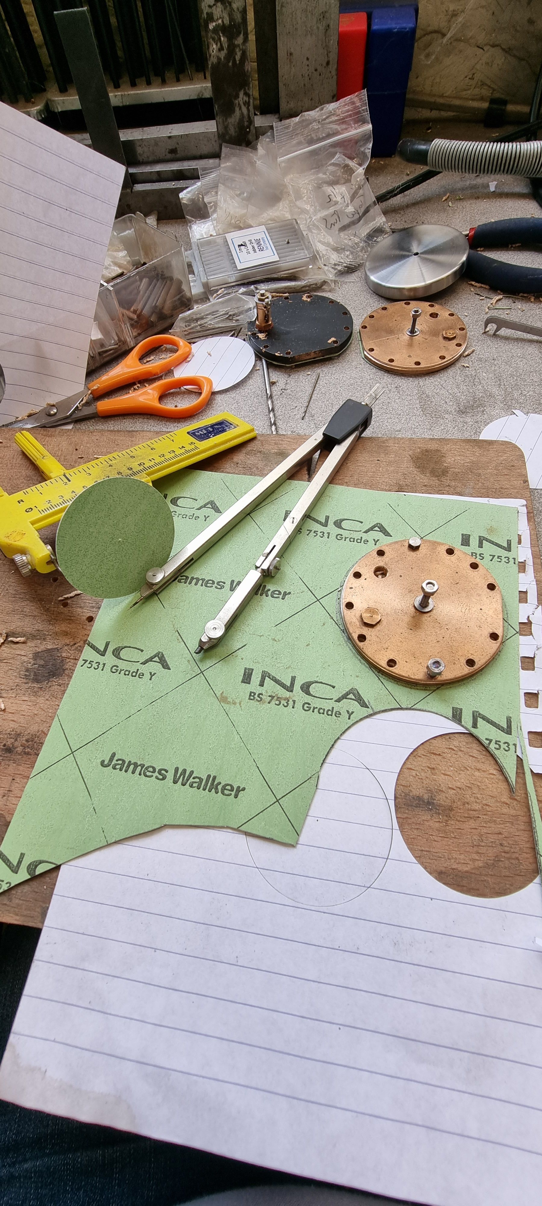
First up is making the gaskets for the cylinder covers, Don states to fit these dry, I can't see any reason for this as there's plenty of room for gasket material, in this case 18 thou thick.
I first measured the lip that sits in the cylinder, NB: there is no lip in Don's design but I added one for two reasons, first, it saved me machining the middle cylinder face so deep, it was a tough enough job as it was having to do this by hand. Also it meant that it was far easier to get the cover central when fitting to the cylinder.
I used an old tool that was originally designed for cutting circles from plastic sheet, it was perfect for this particular job. The picture shows the compass used which is yellow.
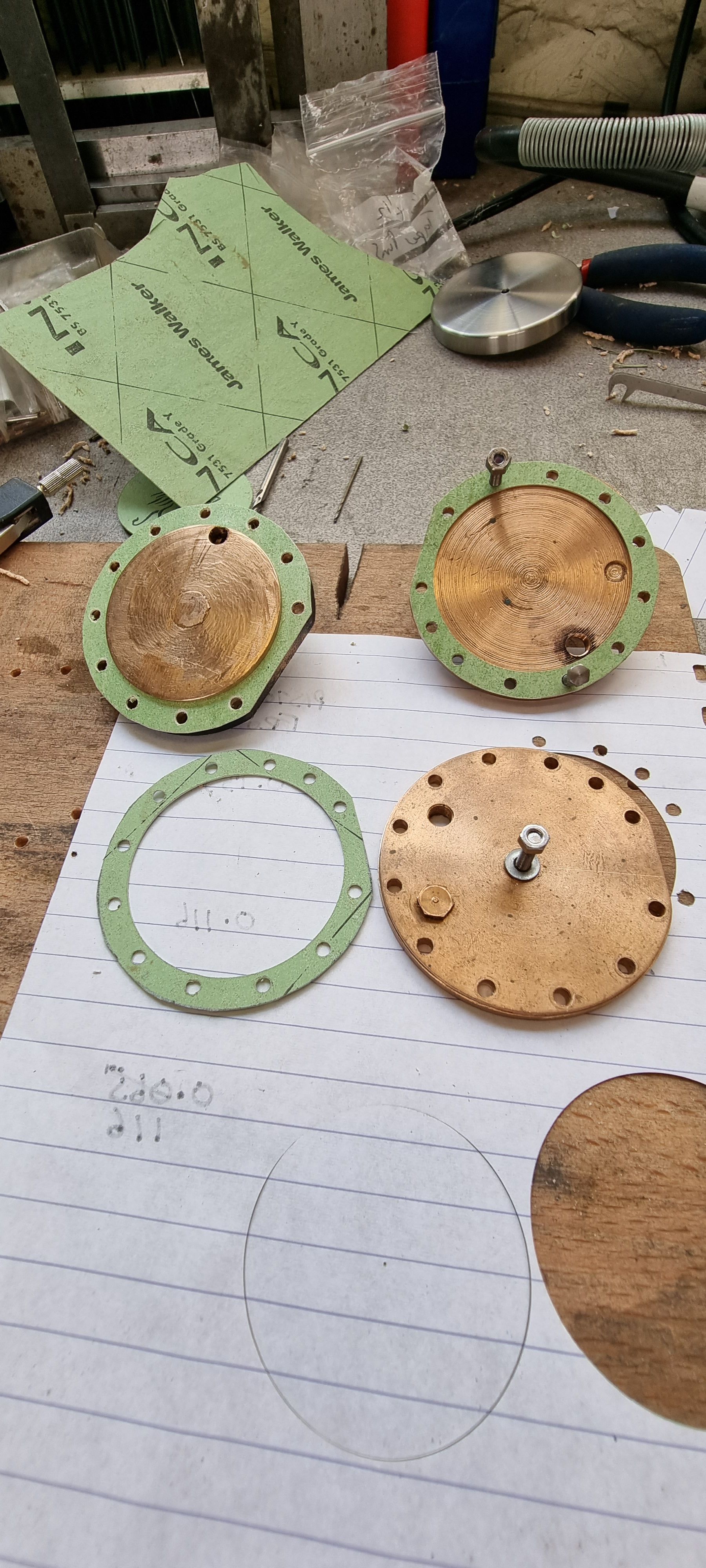
.with the middle cut out of each, I then began to drill through each hole for the studs. I did the first two at opposite positions and put bolts through them to hold in place while drilling the others. The final job was to trace around the outside edge and cut out with scissors.
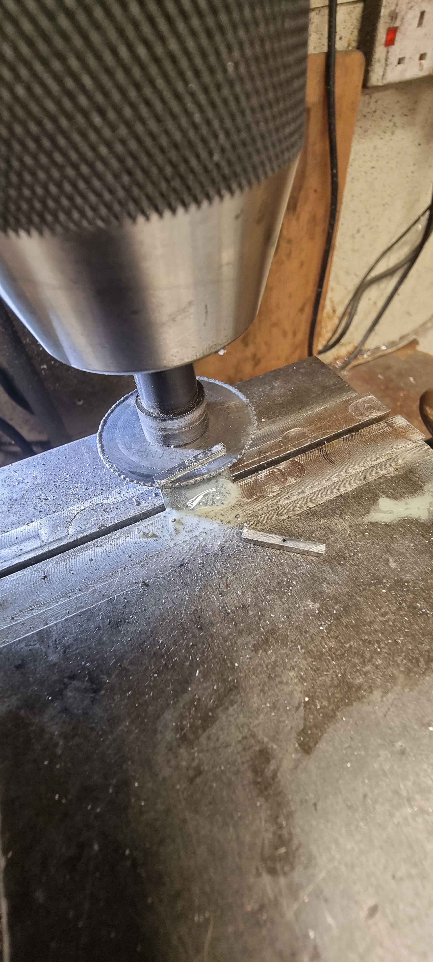
Next I moved to the dummy cotter joints, I had originally intended to cross-drill through the crossheads and piston rods as a belts and braces approach when fitting the dummy cotters, You may recall that these are not needed as the piston rods are threaded and then locked against with grub screws but I tried anyway. The middle cylinder went fine, one of the outside cylinders did not, even though I was using cobalt 1 mm drill bits one snapped as it broke through the piston rod thread on the rear face but didn't get all the way through the crosshead and thus couldn't be tapped out from behind. After cursing myself and swearing not to buy cheap drills again, I decided it was best to ditch this idea altogether and just fit the dummy cotters in the crosshead where the holes had already been drilled. First I needed to deal with the snapped drill bit as even though the piston was in it's correct position I needed to be sure that I could remove it at a later date for when/if I needed to replace the silicone O rings. This is where I was very glad of how I had designed the pistons, with the two holes drilled in each face for tightening when fitting, it was easy using the custom tool made to just snap the drill where it was.
This is where I was when the mishap occurred, hey I'm not infallible guys...:)
For the cotter joints I have used some 1/16 taper pins and cut up some slices of 1/16 steel to fit the slot already machined into the crosshead. Having first machined the top square, I drilled a 1.2 mm hole down the middle deep enough to give me two cotters and then sliced them off using a slitting saw. Alas, I forgot to take a picture showing the pins through the steel slices, basically, they were measured and cut to size to fit each crosshead and then silver soldered together. The pin was then cut off the top and trimmed underneath until each cotter was a tight fit, for added security a small dab of Loctite 638 was applied.
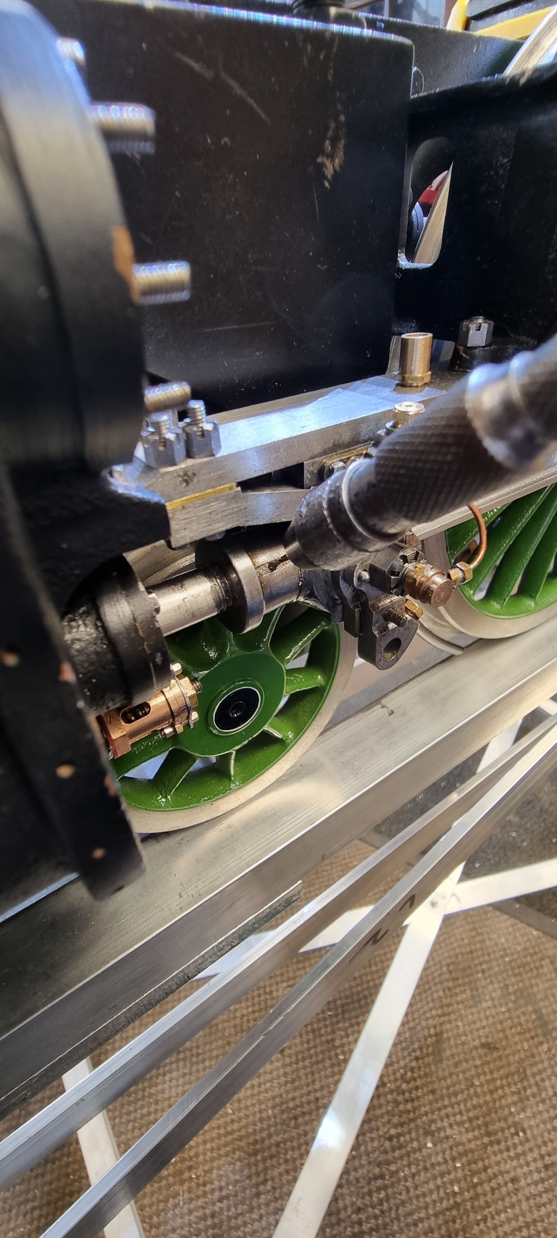
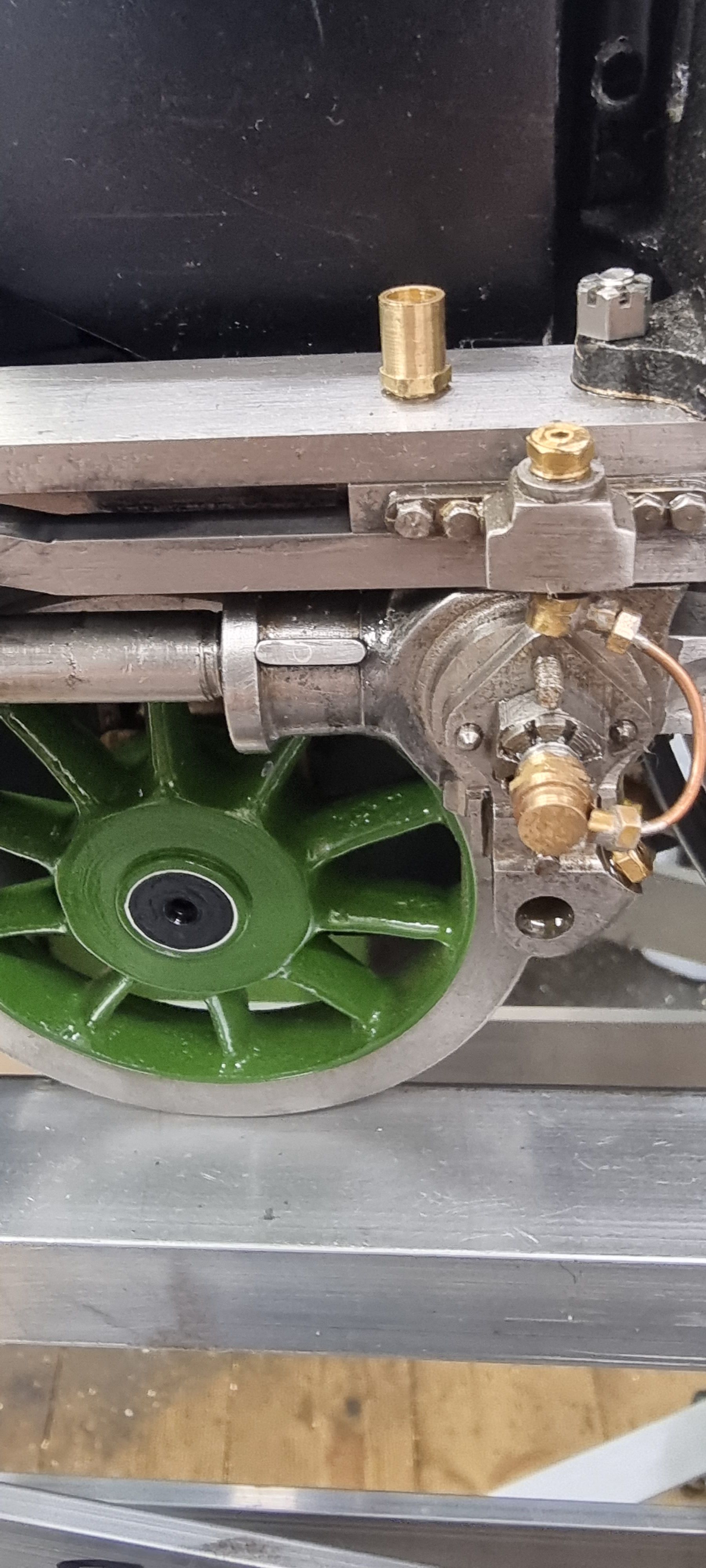
This picture shows a dummy cotter joint finished, note the model is covered in oil, as things have progressed I am now oiling the motion as it gets moved about a lot. Getting very dirty..:)
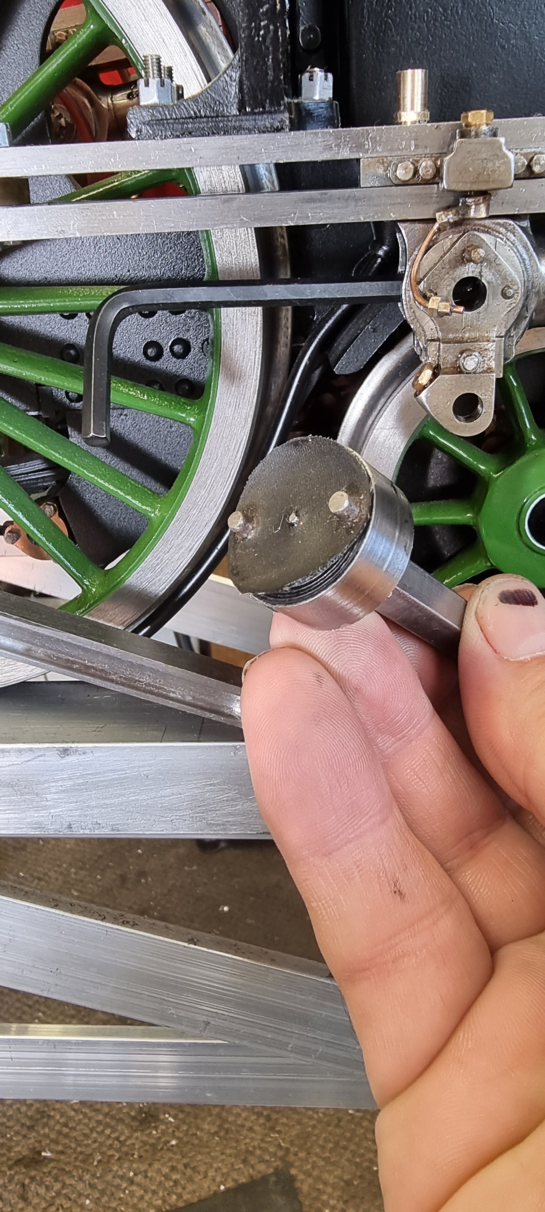
A couple of pictures to show the final procedure for fitting the pistons, this picture shows the custom tool which was later also used to snap out that naughty drill bit.
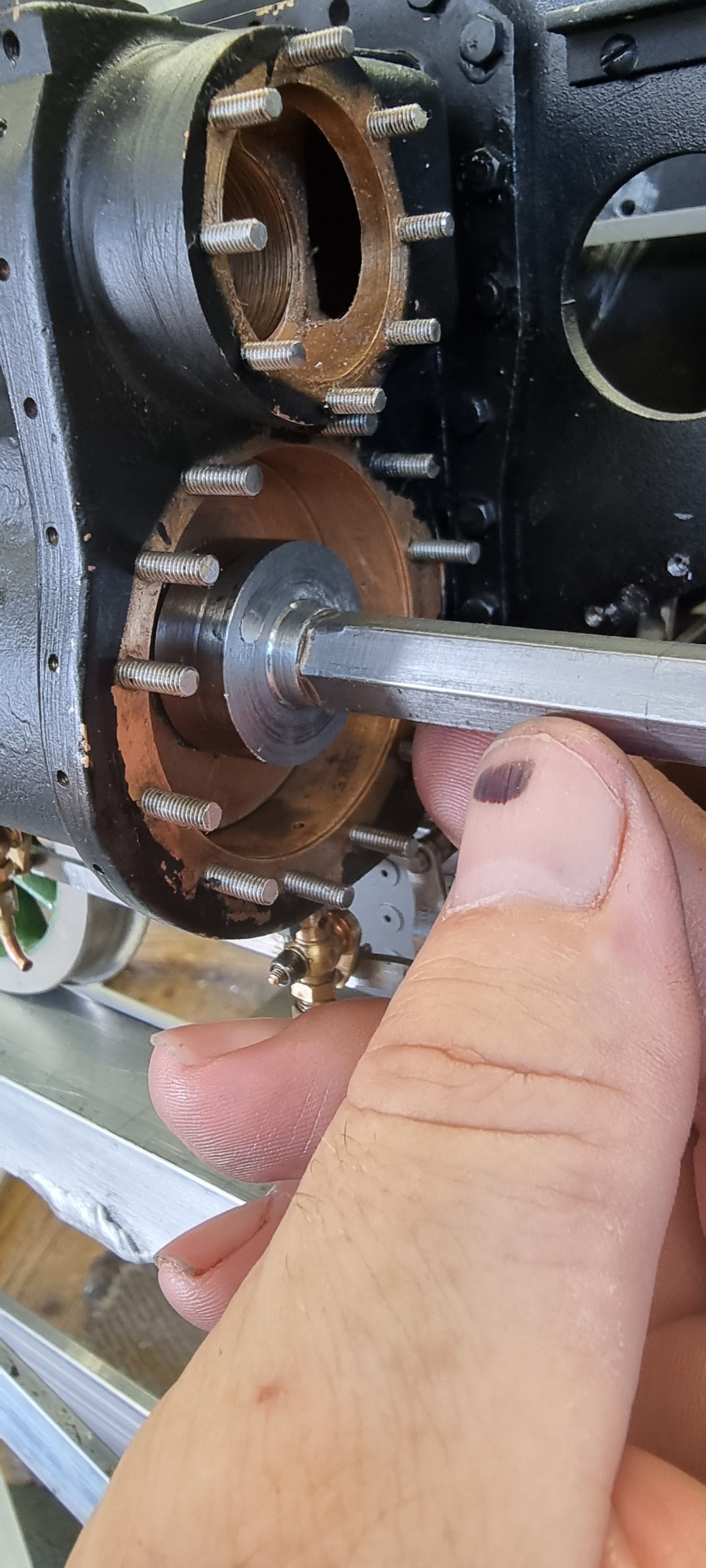
And here we have the crosshead with the connecting rod dropped and with the piston in it's correct position, ie the port is partially open at full FDC and there is clearance at RDC the piston rod and the grub screw were tightened against each other. I don't need to worry as to whether the port is open at RDC as Don thoughtfully included a steam passage in the casting across the rear face of the cylinder. remember, these are blind bore cylinders and thus impossible to see if the port is open or not. The important thing is the front ports are open and the piston doesn't foul the rear. Note the other view of the tool made for tightening.
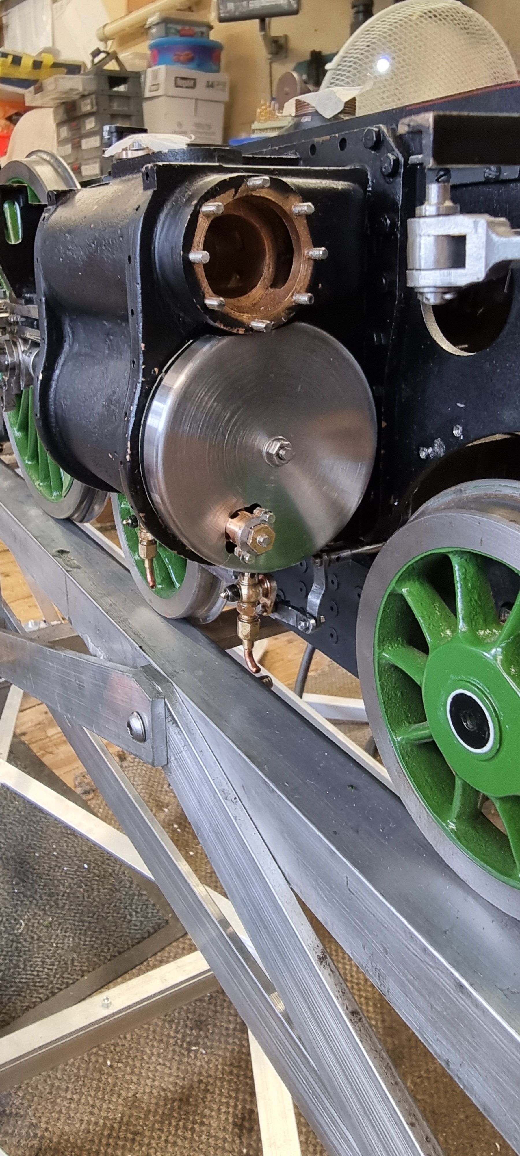
I could now move on to fitting the cylinder covers and their relief valves. First up was the middle as there are no stainless covers to fit here. The gasket was soaked in oil and bolted home following normal procedure of tightening opposite bolts.
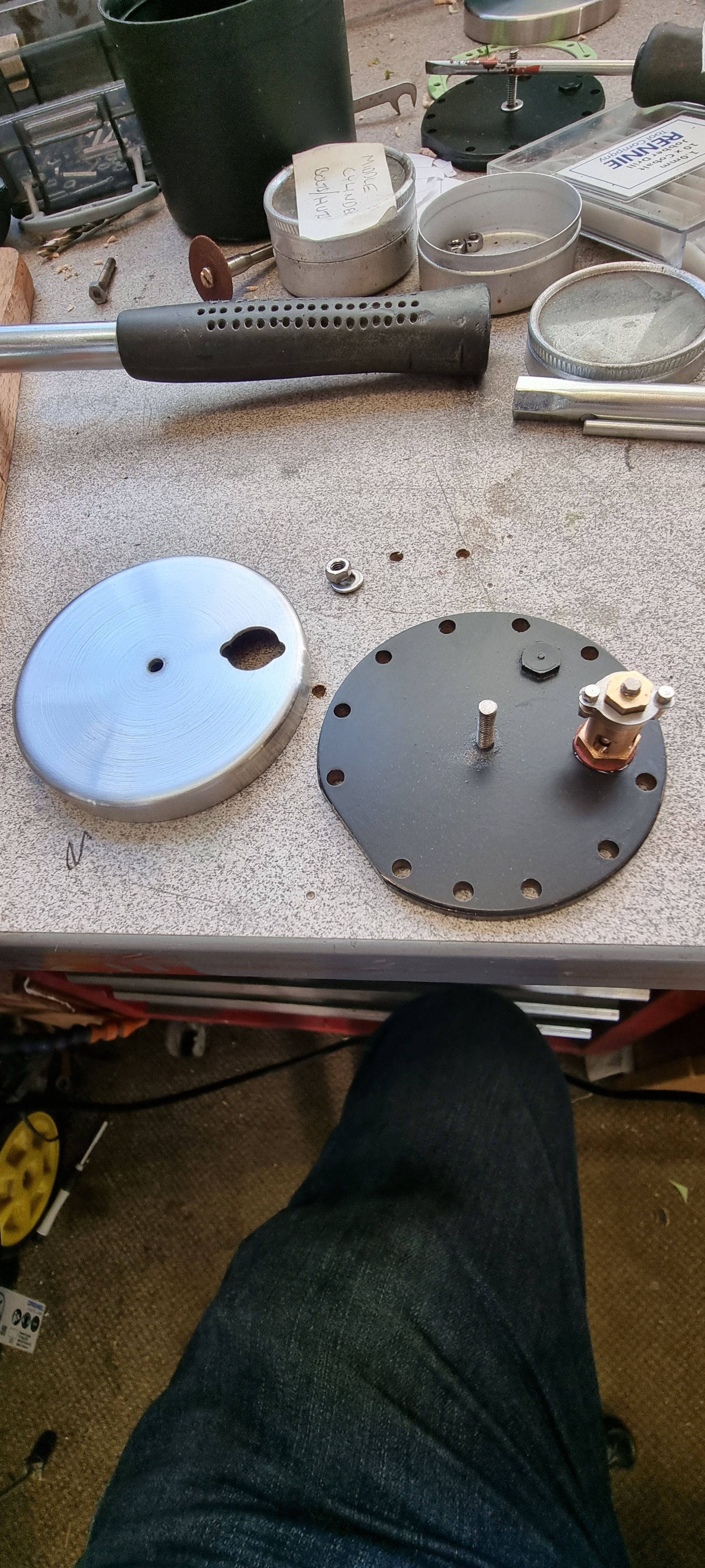
It was then time for the outside cylinders and these needed a little extra thought as the stainless covers need holes drilling for the relief valves to poke through and also have a section removed to clear the steam chest. I approached this carefully as I wanted the stainless covers to be a good fit. After consulting some pictures which I took in 2016 I used a transfer punch to mark the inside of the stainless cover by tapping it through the relief valve hole. I then took measurements of the valve body hex and also the two wings that stick out on the end. I came to the conclusion that the main hole required was 10 mm to give a little clearance and that a 4 mm cutter set at 5mm off centre would give me the shape required for this hole. The final shaping was done by hand with a file.
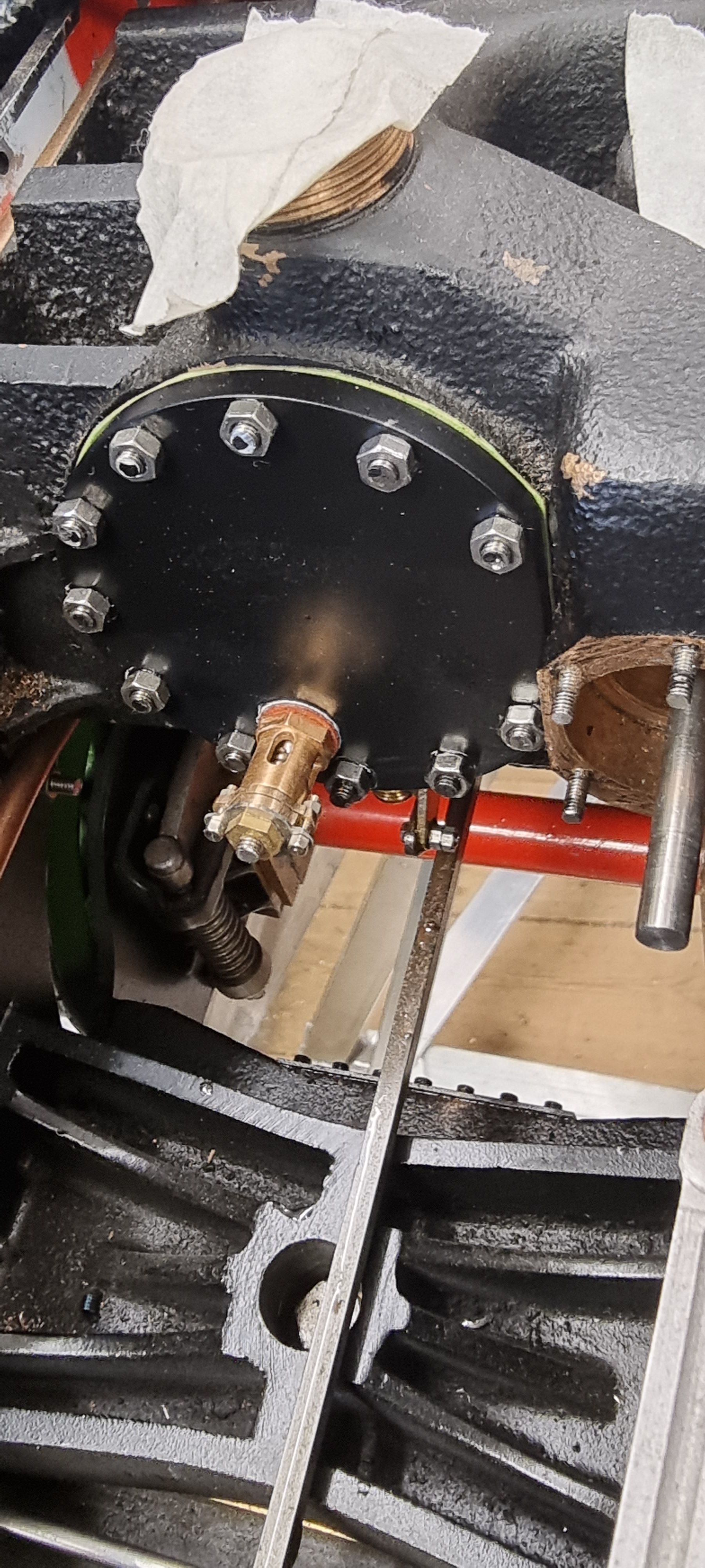
This picture shows the first outside cover with it's stainless plate nearly ready for fitting. Note the relief valve needs to be fitted first and that the stainless cover needs to slide over this when on the cylinder. I have tried to follow photo's as to where to place the small recess cutouts in the hole. The valves tighten up at just the right orientation, I'm sure that I covered this in their build but can't recall now.
I next fitted the cover and buttoned it up tight. Note the nuts are very close to the edge, this was allowed for during machining of the cylinder covers for the stainless covers to clear the nuts.
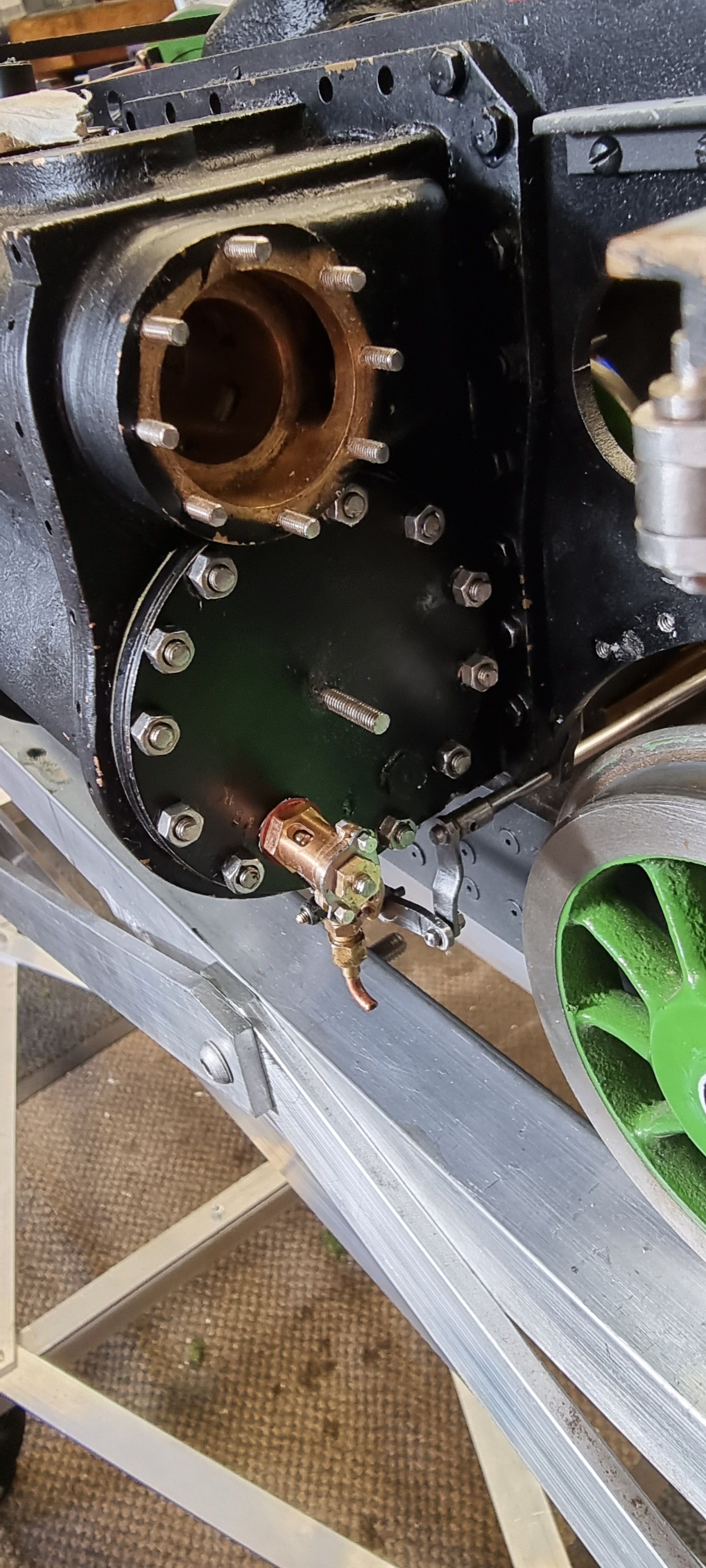
I then began to trim the stainless cover using a variety of dremel slitting sawa and diamond grinders to allow it to fit at it's correct orientation. Here I have got as far as to allow it to fit correctly position wise but just needing a small amount left to remove to allow clearance of the steam chest and then fit snugly over the cylinder cover. The black marker pen guides me to what needs removing. It gets a little confusing with all these 'covers'...:)
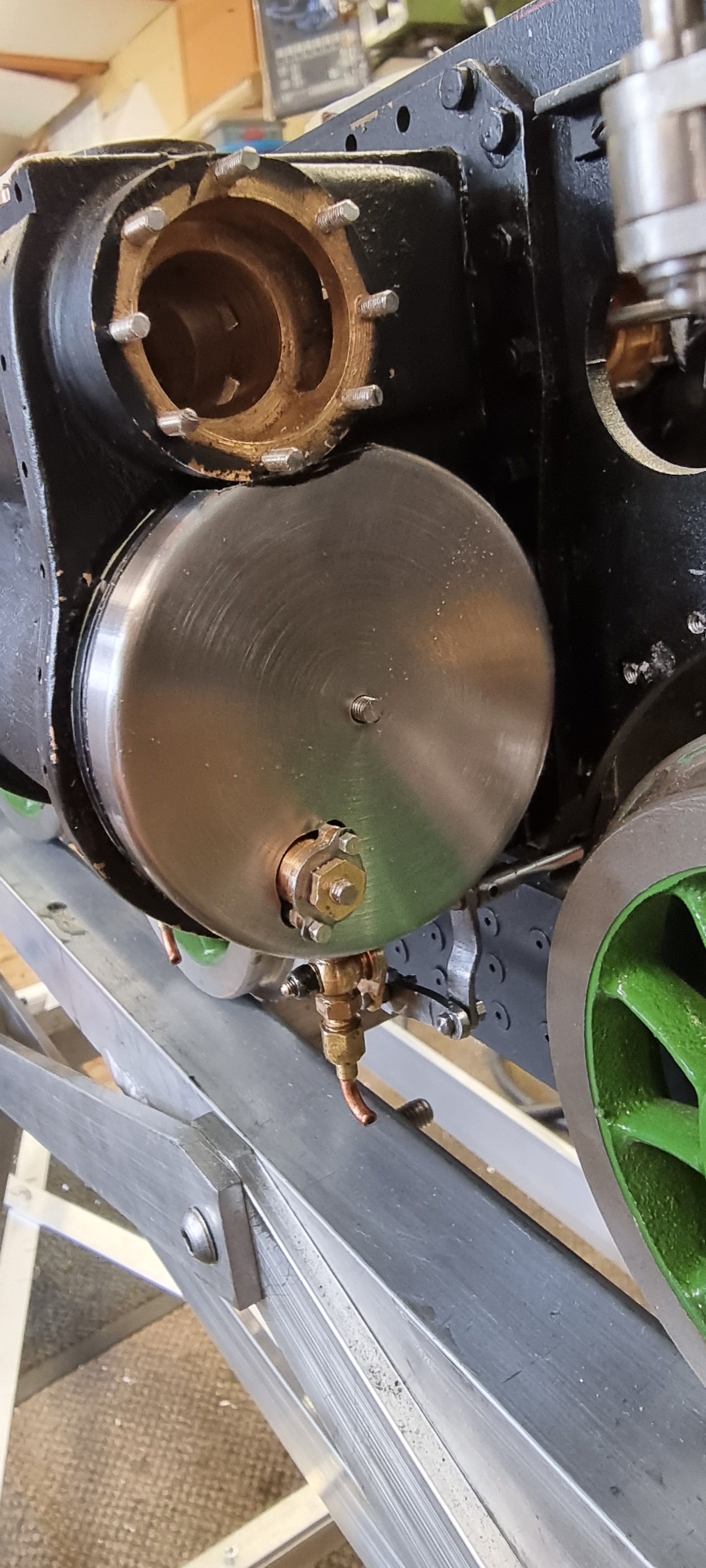
And here we have it, the money shot as we say in film/tv. I'm pleased with the result, I still have the other outside cover to finish but that should go smooth enough. I can see that I need to get some paint out to touch up in a few areas, I'll probably take care of this once the motion is finished.
