I decided that now was a good time to revisit the valves to finish off the spindles and fit their crossheads. 2 each for the left and right cylinders but only one crosshead for the front of the middle cylinder, a rear isn't needed due to the 2;1 conjugated valve gear and thus the rear section of the spindle is a sliding fit into a rear housing fitted where the valve guide would have been. Note that for the middle cylinder the valve spindle is fitted in reverse to that of the two outside cylinders, I needed to remember to fit the bobbin the right way around for this cylinder so that I can adjust the valves using Jim Ewin's design allowing adjustment from the front only.. Warning there are some very close pictures here using the macro lens which show a whole host of very dusty parts that need addressing with some cleaning and a little paint later, much later.
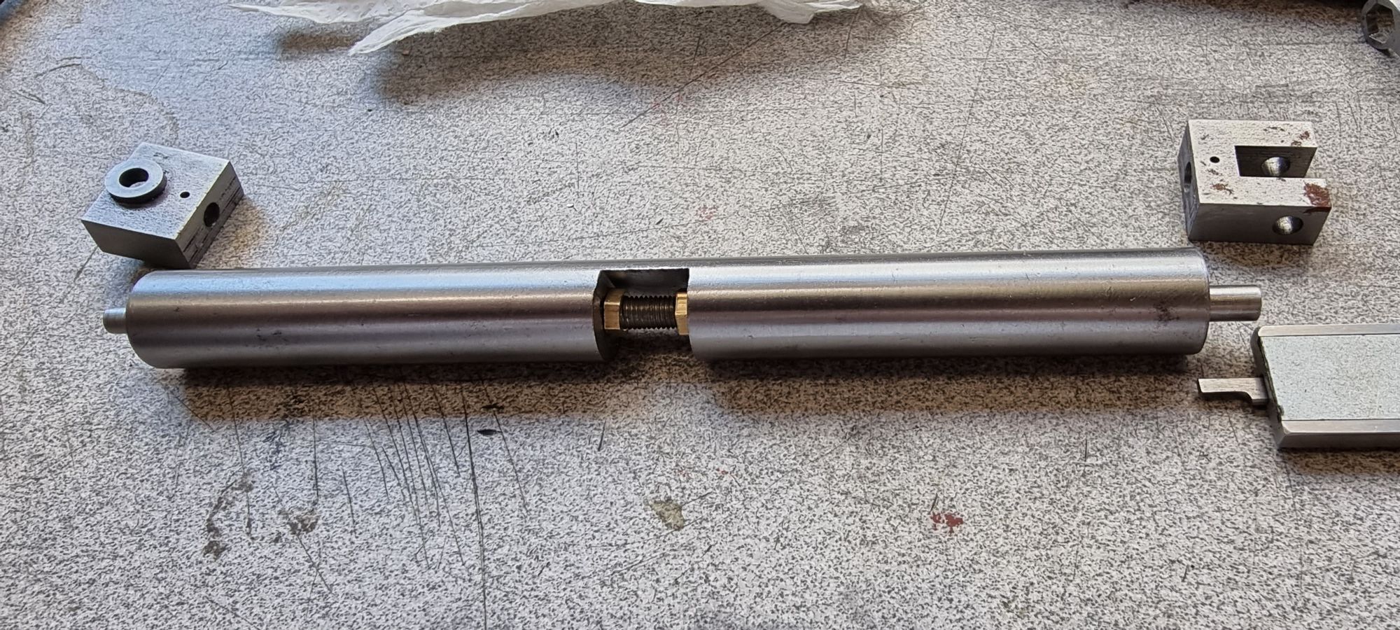
Currently the spindles are slightly overlength, they are ' to drawing' but IIRC Don left them slightly over length until final fitting, that was certainly the case for the piston rods. Tucked away on sheet 10 Don gives the dimension of 5 19/32 as the distance between the two crosshead inner faces. I'm confident that the crossheads are exactly to drawing and so made up a jig to hold each spindle for cross-drilling. I selected a length of steel bar with a diameter slightly smaller that the width of the crossheads and machined to length, 5.5938. This was bored to allow the spindle to be pushed through freely, the spindle is 3/16 (0.187) at it's widest end and 5/32 at the other. I chose a drill size large enough so that two nuts could be threaded on the spindle and tightened. The steel bar had a section milled away from its centre that was deep enough for the nuts to turn, hopefully the picture will show what I'm trying to describe.
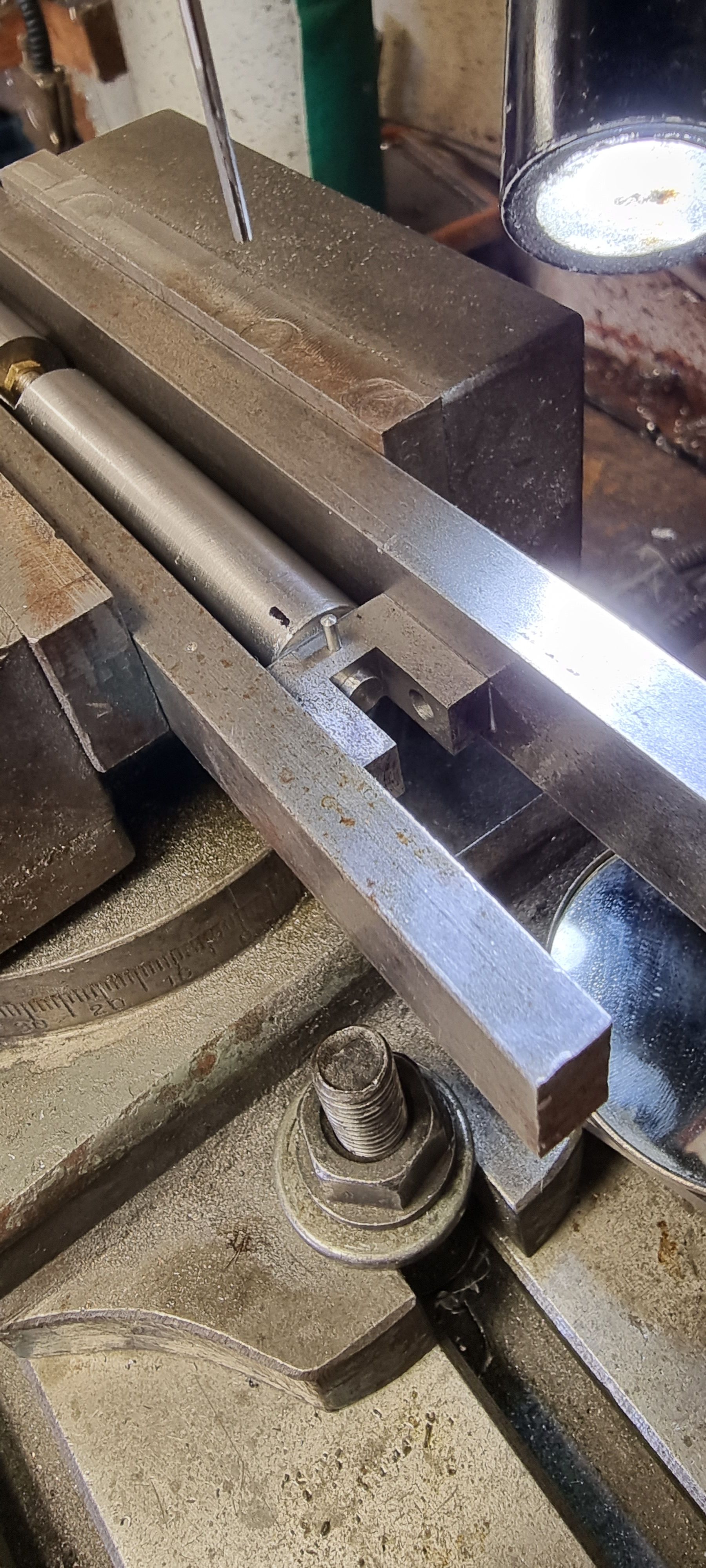
The 3/16 x 40 thread ( 3 1/16 long) is in the middle of the spindle with 1 9/16 equally either side, one at 3/16 and the other at 5/32 dia. Since the thread is bang in the middle I fitted the spindle in the jig and locked it in place with two 3/16 x 40 nuts which were turned from brass hex that were small enough to fit in the jig's recess. The first picture shows the jig with a spindle held in place, I measured each end with the tail of the Vernier until satisfied that the spindle was in the middle. The two nuts were than locked against the opposite faces of the machined recess in the jig. Note the two types of crosshead are also in view.
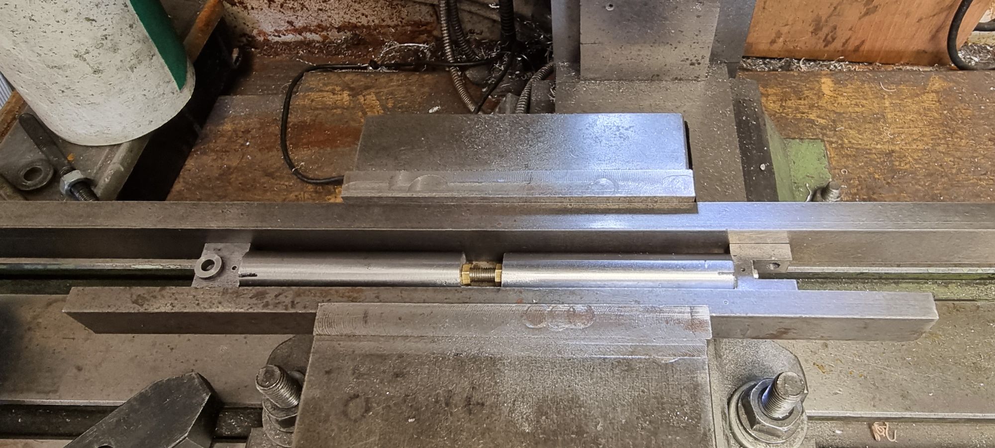
The next picture shows the jig being held in the machine vice ready for the spindle to be cross-drilled for a 1/16 taper pin. A couple of things to note, I have already covered that the length of the jig is set for the correct distance between the cross-heads. As can be seen the crossheads are up tight against either end of the jig. The other thing to note is that the cross-drilled holes need to be exactly on the same plane, this is easily dealt with by the two lengths of steel that the jig is held between. As the crossheads have flat sides this ensures that they are both on the same orientation. This is also why the jig needed to be a slightly smaller OD than the width of the crossheads as mentioned previously.
Here we see that one of the taper holes has been machined and a taper pin temporarily fitted, it will be trimmed to length later. As can be seen there is a small tail of the spindle still showing, I'll probably trim this off but will wait to see if it causes an obstruction first, I suspect that it will need trimming. With things set as above the final job is to repeat the process on the other end.
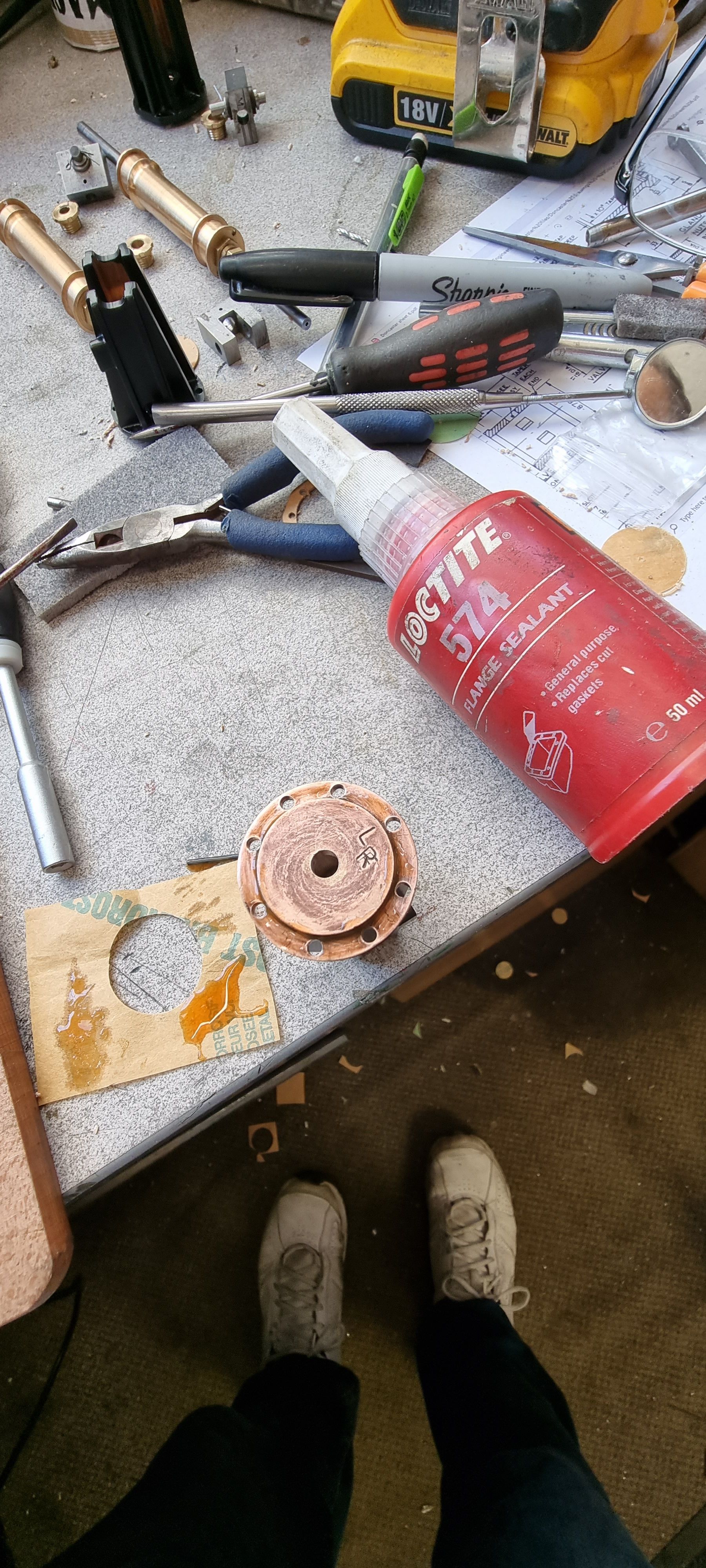
The valve guides were finished many months ago but hadn't yet been painted, so that was the next job. You may recall that I mentioned that Don said to fit these and the cylinder covers dry, ie no gaskets? I couldn't really see why as IIRC he only states that things are very tight in this area from which I assumed that the gasket thickness may upset things. However I have given this some more thought and although I can't see any issues with the cylinder covers having gaskets it does occur to me that when fitting gaskets to the valve guides it may be possible to throw the spindle centre's out a small amount, what I mean is, if the gasket is squeezed more on one side than the other it could possibly angle a guide slightly? I don't really like the idea of fitting them dry, especially the middle cylinder so will use a flange sealant, in this case I'll use Loctite 574 which I am familiar with from rebuilding my Porsche engine. This picture shows the middle cylinder rear spindle housing now fitted, however, just to contradict the above, for this end I have used a gasket.
A picture to show the flange sealant used.. the stamp shows this is the rear cover for the L/H cylinder
Moving to the opposite side, this is the rear R/H cylinder valve guide and here I was struggling to fit the nuts until I realised that i was using the wrong ones? That is I should have been using the head size smaller 8 BA nuts as planned.
Things became easier and looked much better when the correct sized nuts were used.

I had to get a little creative when fitting the inside nuts, I found shaping the laser cut BA spanners provided by Model Engineers Laser ideal for this purpose. later when using a new set I'll revisit these tools and make up a proper shaped set for the various jobs required on this larger model.
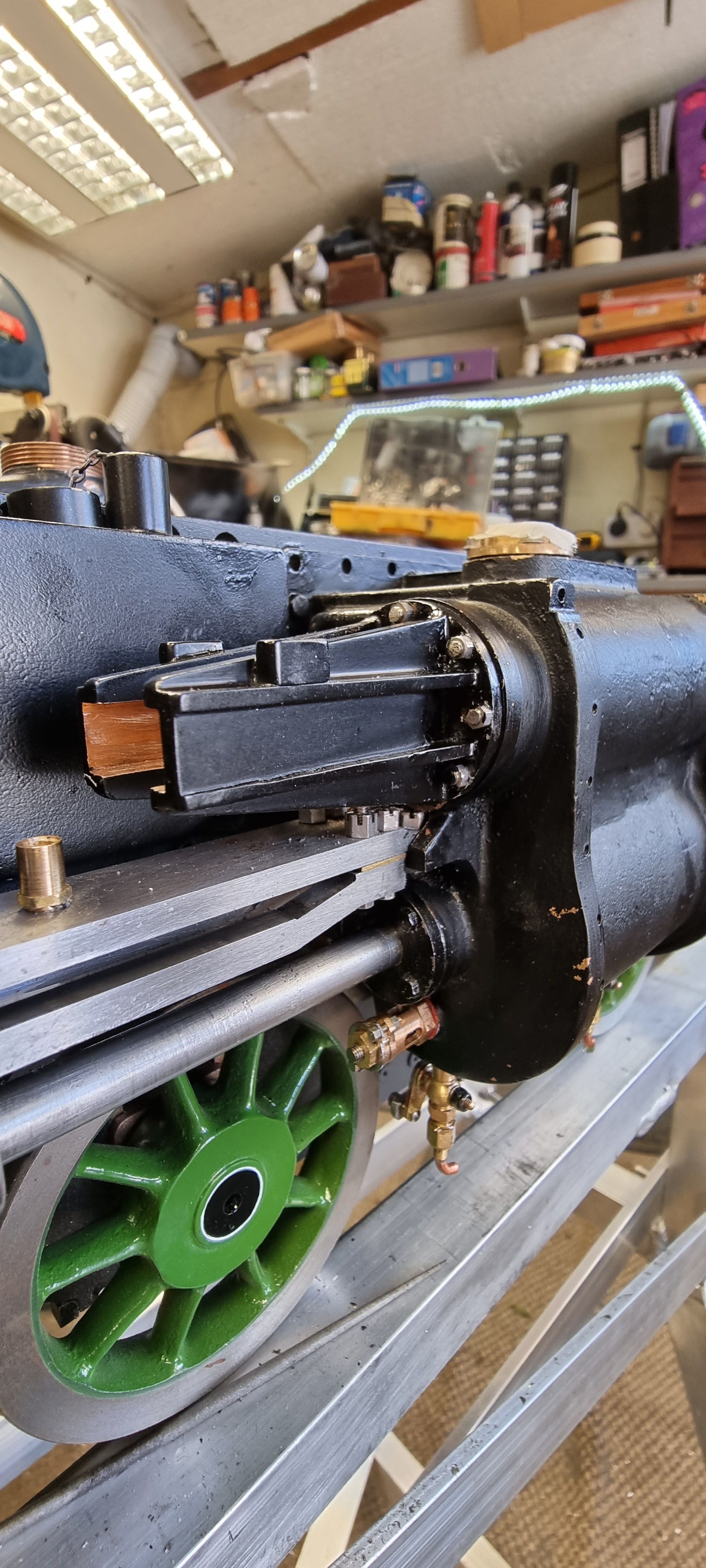
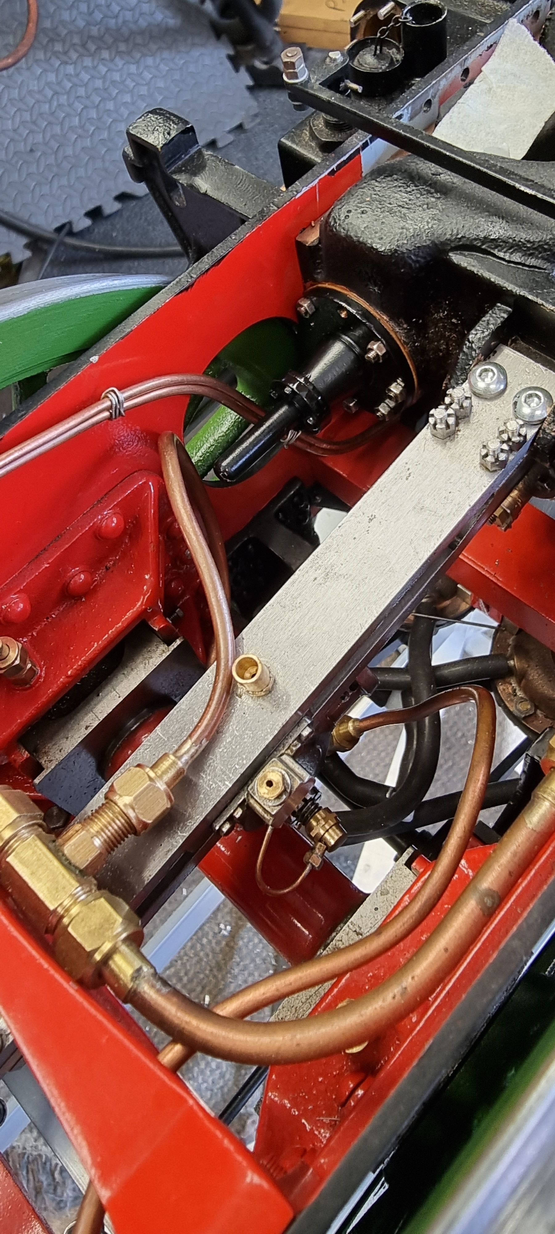
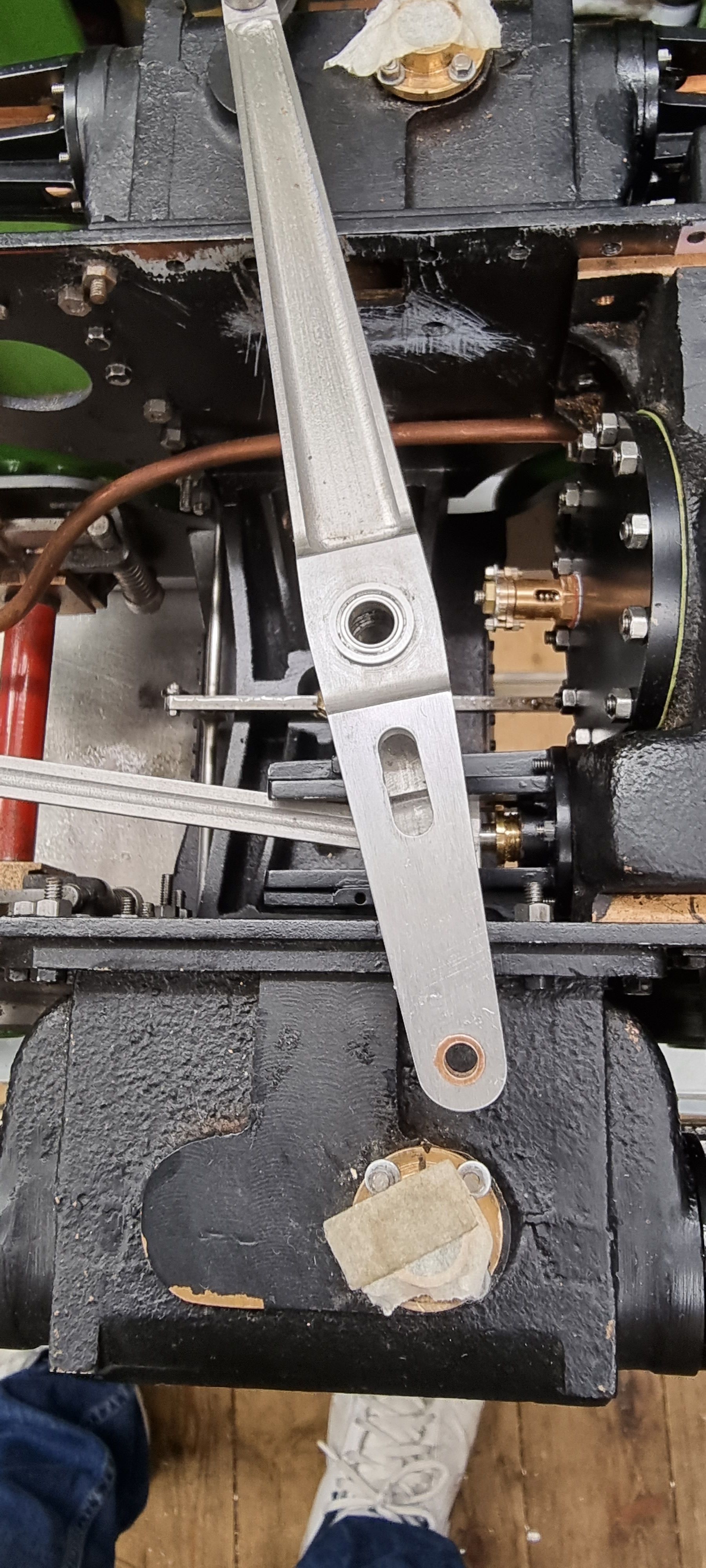
Here is the middle cylinder with the crosshead and it's connecting arm that attaches to the 1:1 lever of the Gresley 2:1 conjugated valve gear.
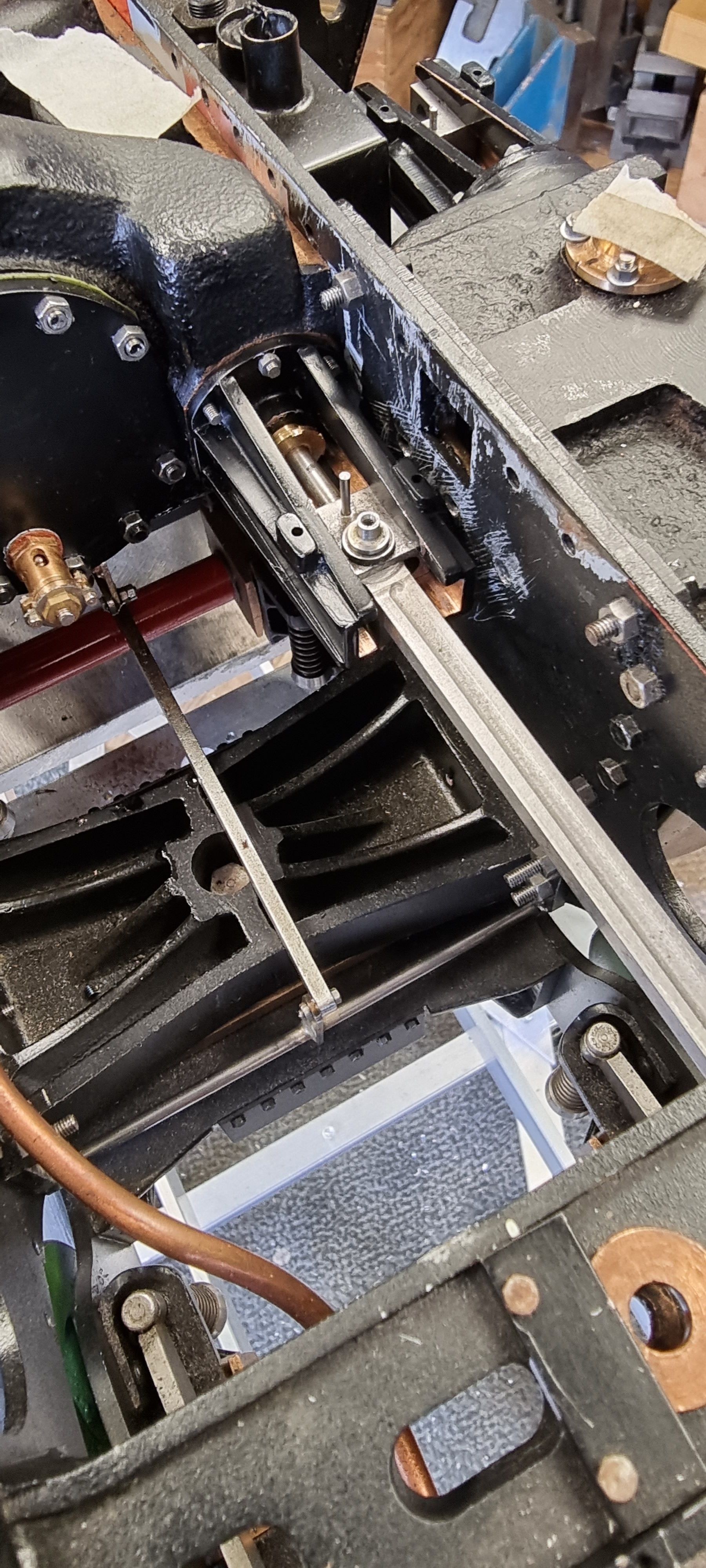
At this stage I decided to make a small modification to the 2:1 lever, it became clear that things were getting very tight in this area and that I couldn't as originally planned fit the 1:1 lever to it's connecting arm prior to installation, the two had to be connected in stitu. There was already a machined slot in the top of the 2:1 stay and so I decided to make use of that and machine a slot into the top fork of the 2:1 lever as can be seen here.
This then allows me to drop the connecting pin down through the stay and then the lever into the 1:1 lever/connecting arm joint below. The pin is then held by small the bolt that's threaded into the lower section of the connecting arm, this was shown much earlier when covering the construction of the 2:1 lever.
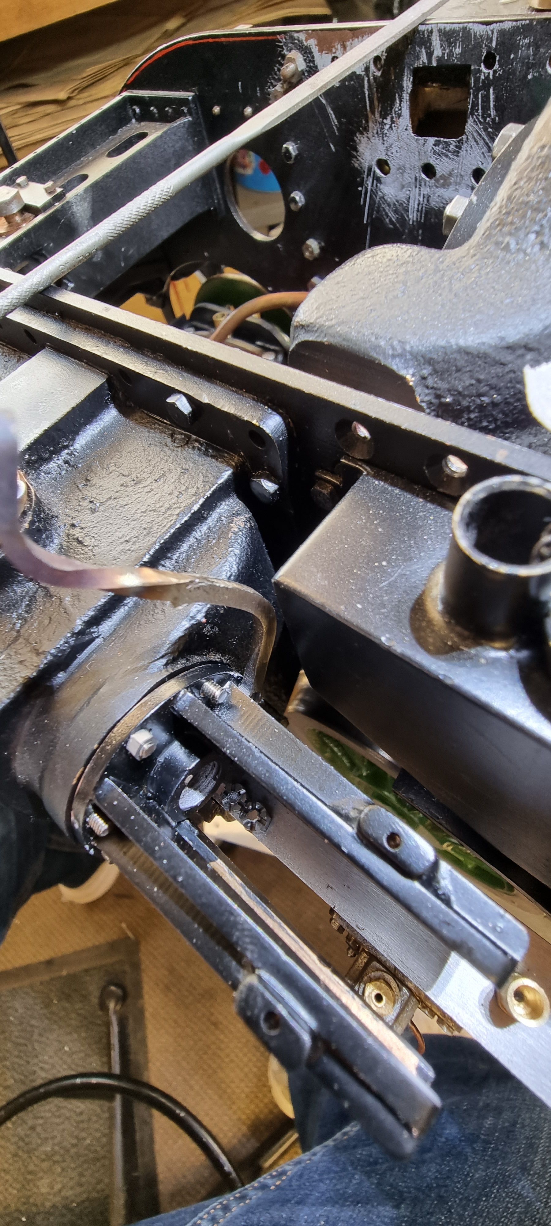
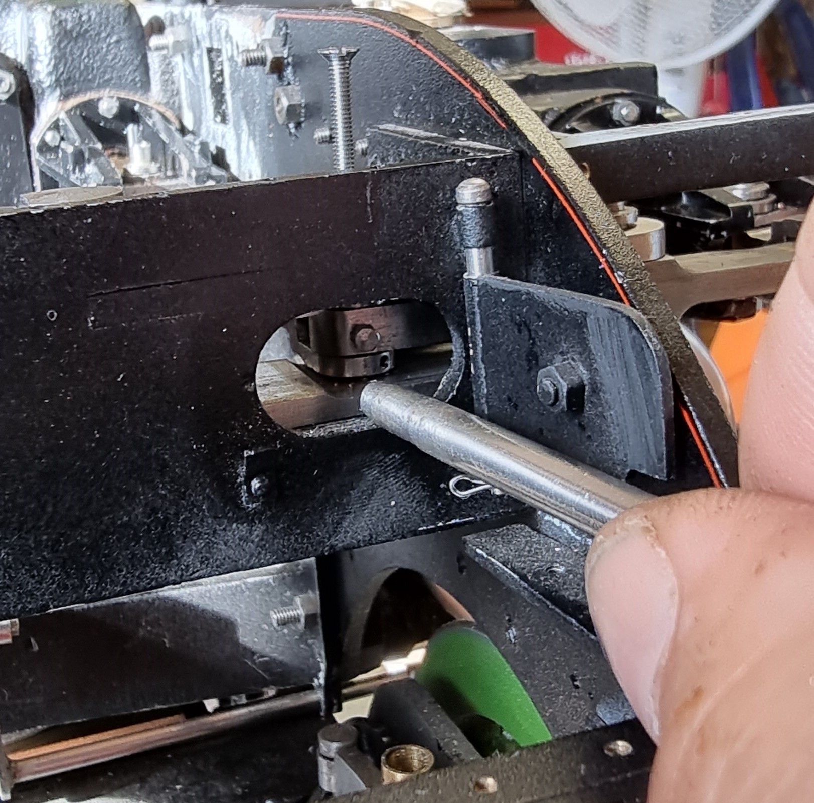
I decided that the 5/32 pin which fits in the bronze bushes here could prove a little difficult to both fit and remove and so I drilled/tapped a 8 BA hole in the top to help with this. Later I'll make up an insert tool but for now I have used a simple inch long screw to fit the pin. Here we see the pin pushed in place to join the 1:1 lever to the middle cylinder connecting rod/arm.
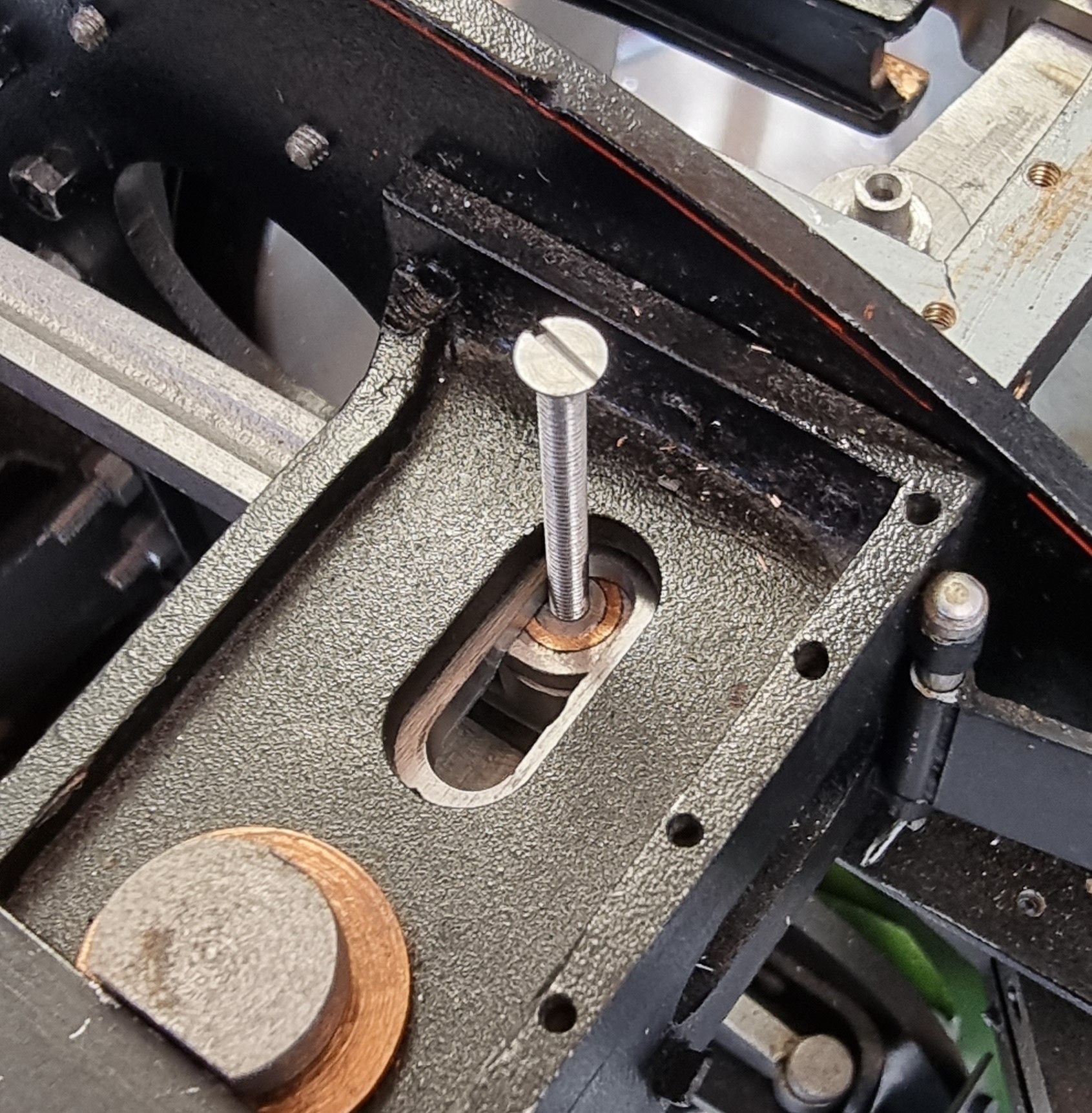
With the pin in place I then screw in a 10 BA bolt to secure the pin through the access hatch in the front of the 2:1 stay. The pin has a small flat area for the bolt to tighten against and I marked the insert bolt to help align the flat face with the bolt. You can just see some black marker pen in the picture above on the thread. When I make the proper insert tool I'll mark the face to give a permanent aligning mark.
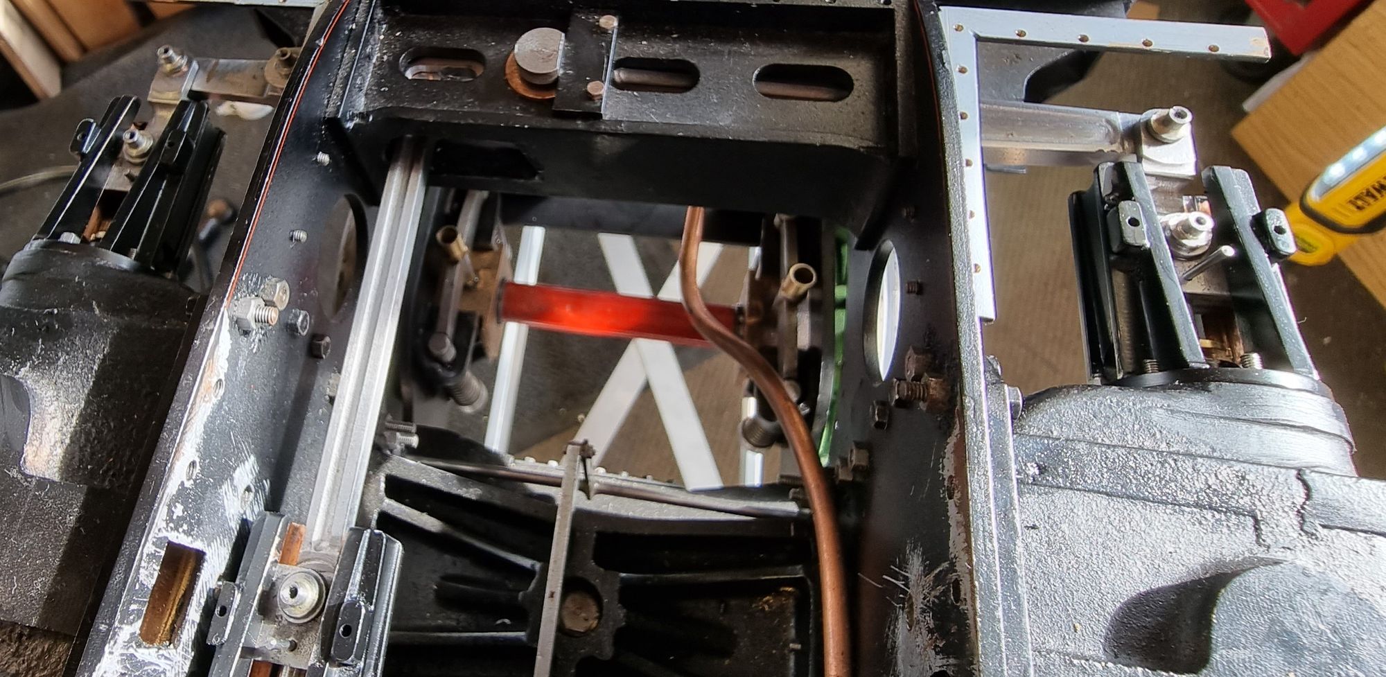
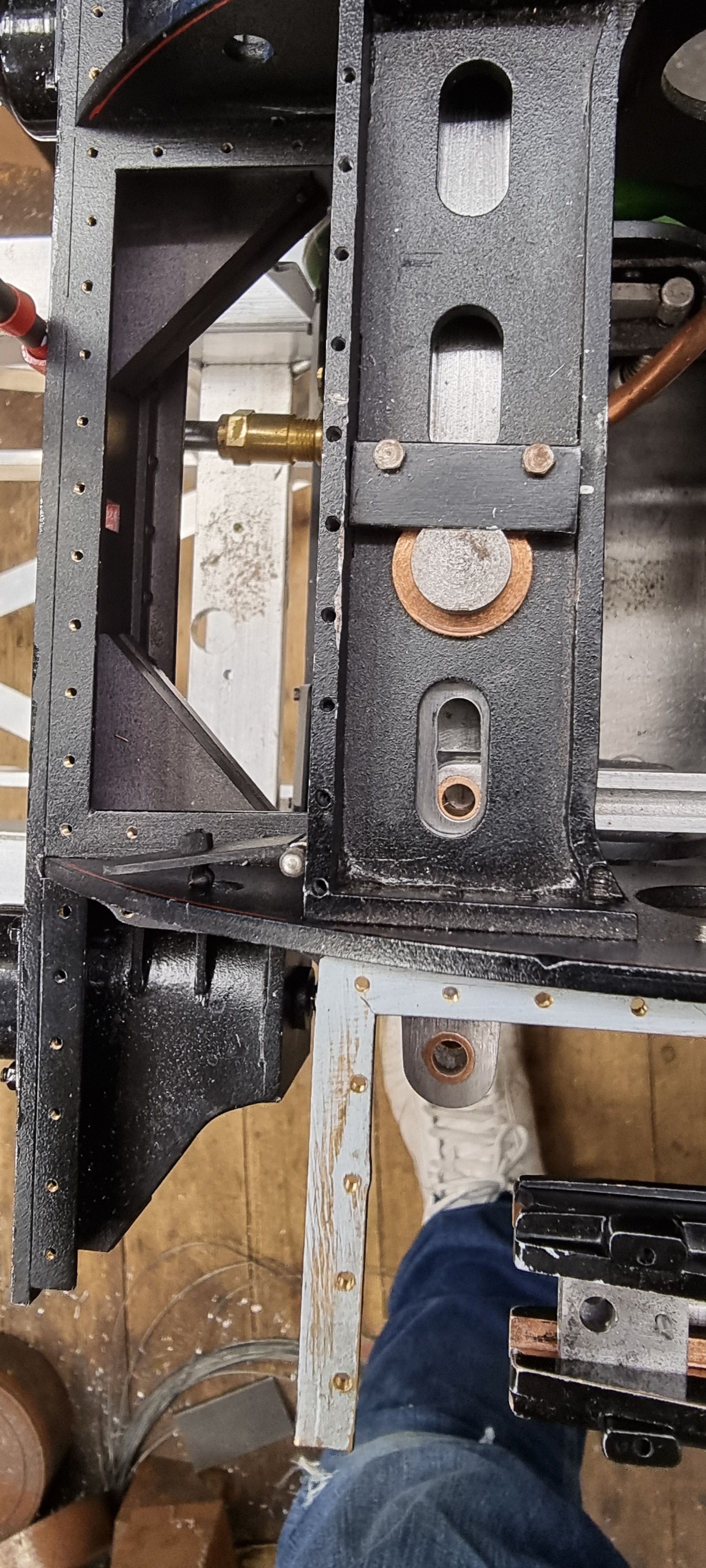
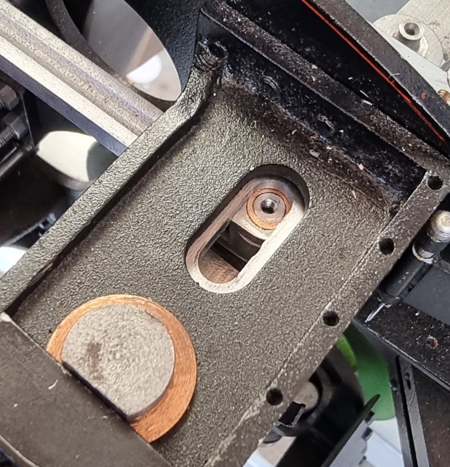
A view from the top after the screw had been removed.
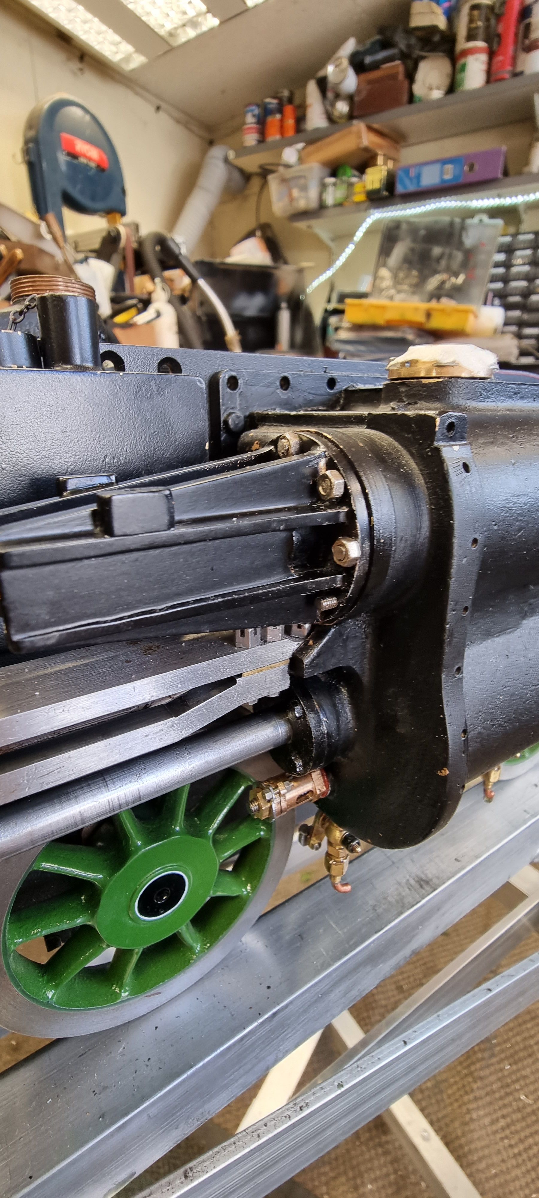
Last two pictures are to show some of the parts assembled... here is a close up of the R/H connecting link showing one of the oil cup pins, these pins have a small reservoir in the top and are cross-drilled for the oil to reach the bronze bush below.
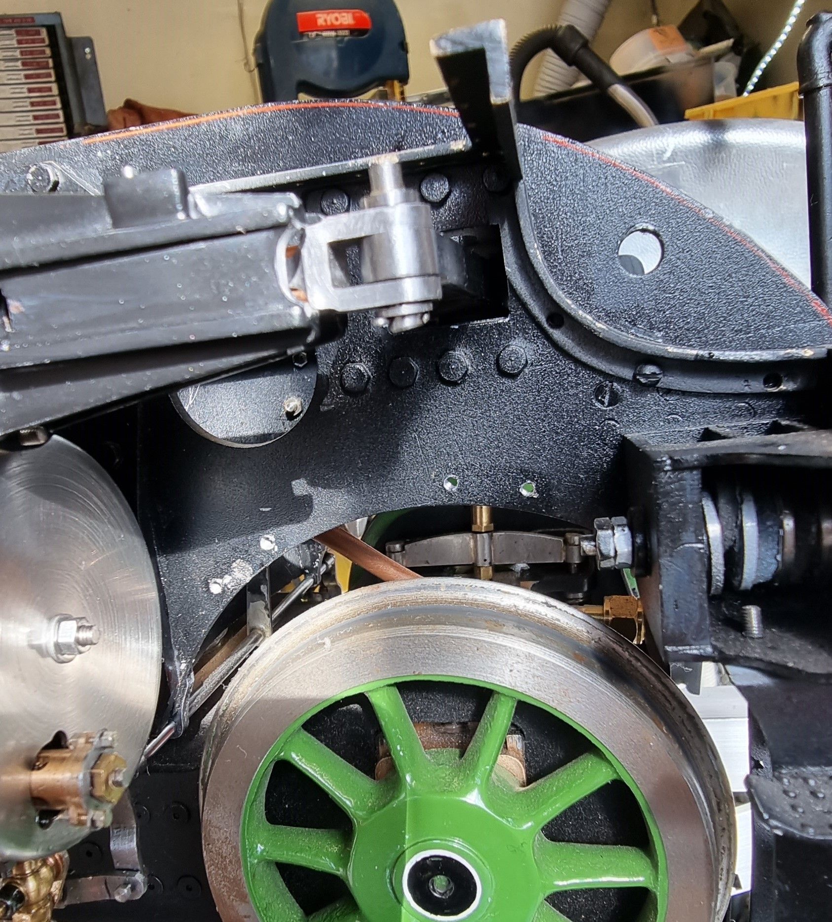
Lastly an overhead view of the 2:1 conjugated system in general, the right hand running board support is currently loose and so is out of line. This is just a dry fit status, you'll note that most of the nuts haven't been fitted and I haven't fitted the bobbins yet although have fitted the O rings and gland nuts to check for alignment. I'll do the final fit/fettle for running once the rest of the motion is completed.