
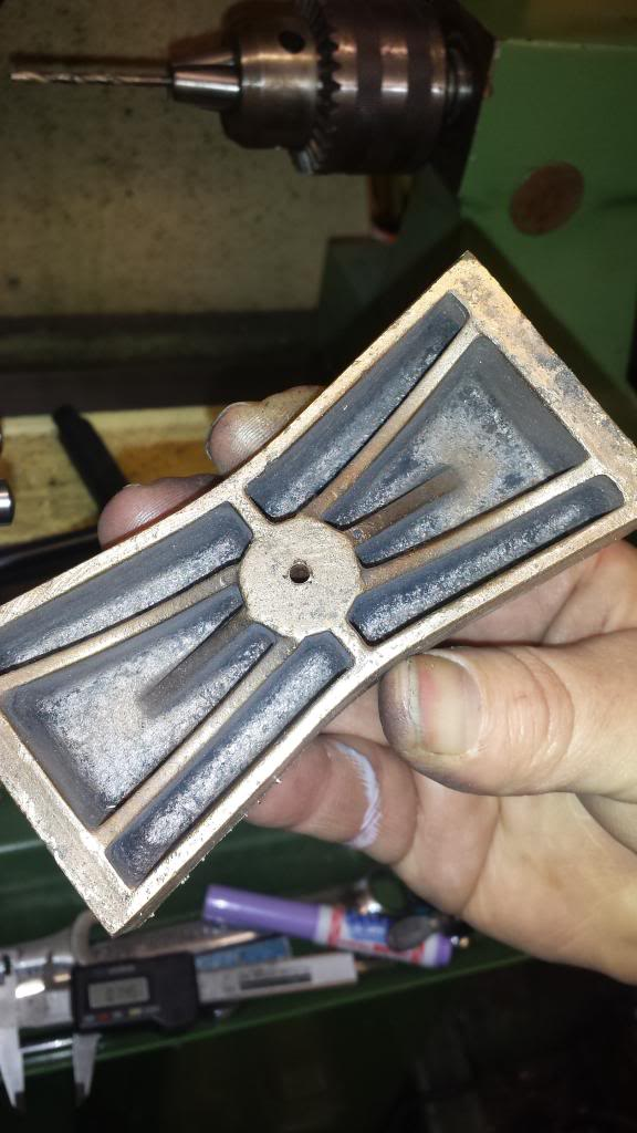
Continuing the build on the bogie I moved onto the yoke, overall dimensions are 2 3/8 x 1 5/8 with the spigot being 1" wide to fit the slot in the bogie centre of which I'm happy to report it's a nice sliding fit with no side play. The tongues that slid along the top face of the bogie centre are 3/16 thick with overall depth of the yoke being 1 1/8. The centre hole is 3/4 for the bolster to fit once I've machined it.
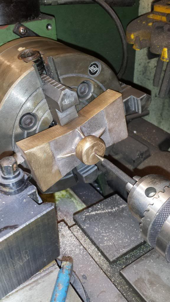
First picture shows the spigot being machined to its width of 1" having already machined the other dimensions as per drawing.
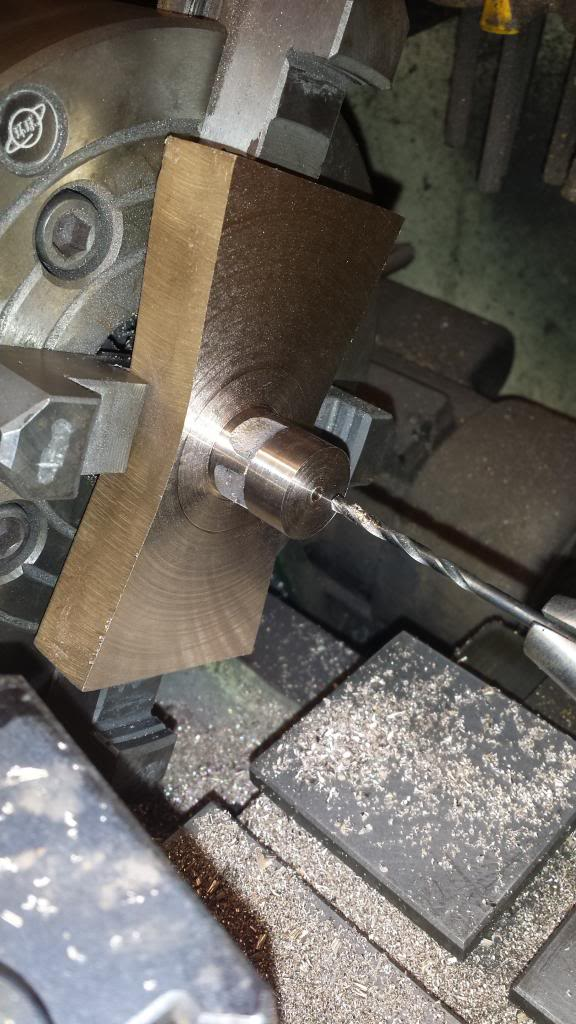
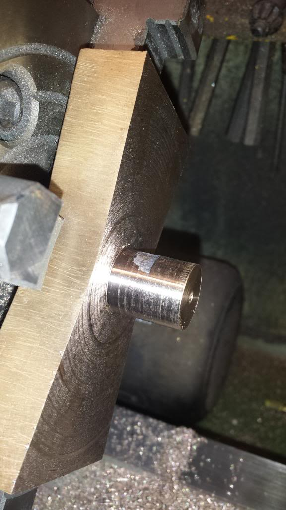
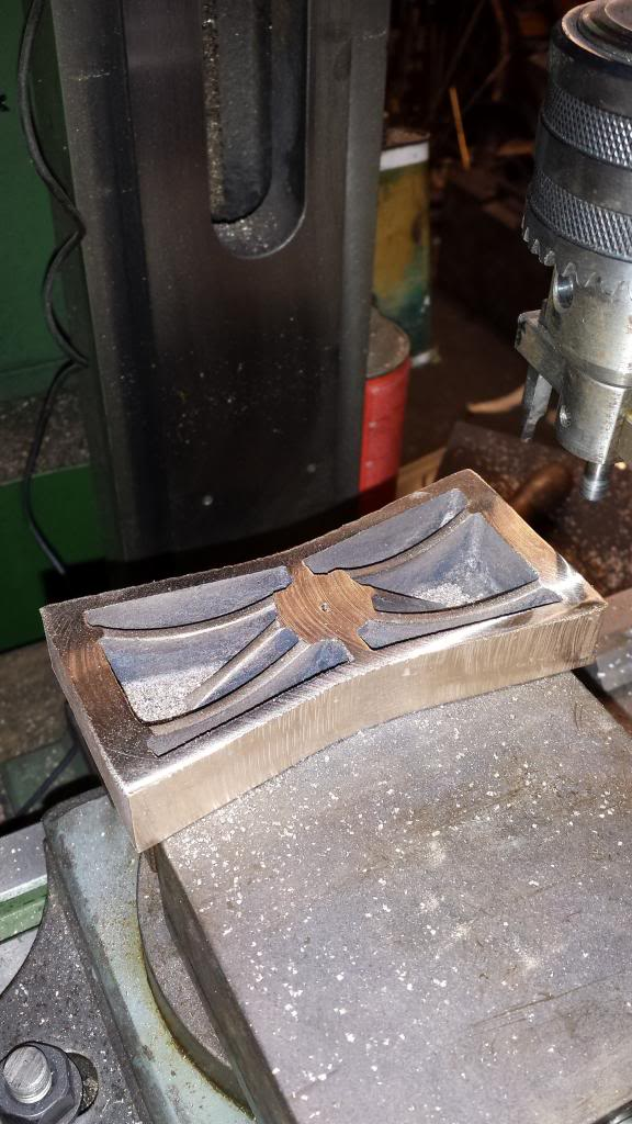
Next stage was to set up centrally in the 4 jaw to bore the core out to 3/4", I could have done this the other way around and in fact is how Don describes it in his description but I found it easier to do it this way around. The two scribe lines are so I can keep an eye on how things are going in regards to lining up with the spigot below, just me being extra careful.
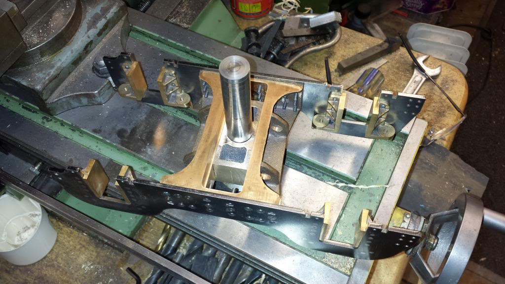
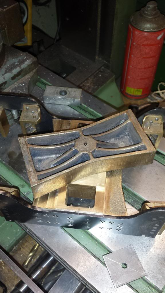
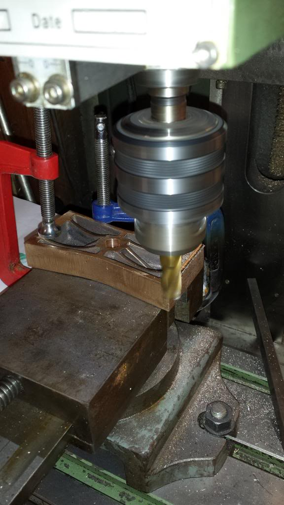
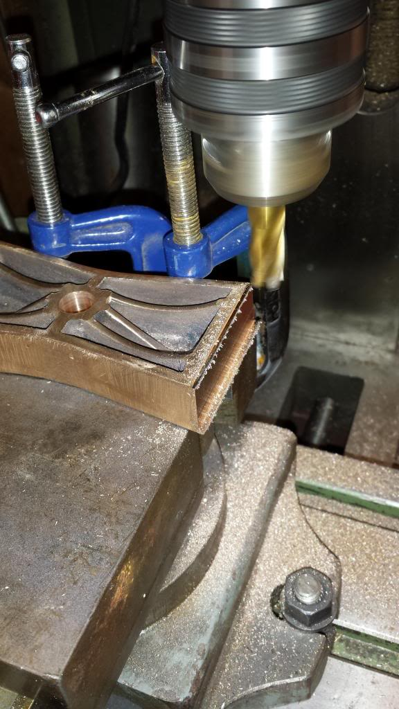
Third picture is to show the yoke sitting in it's slot, I still need to finish the top surface with a little filing. The important thing is that the hole is central to the yoke and that the bogie centre slot is central to the frame
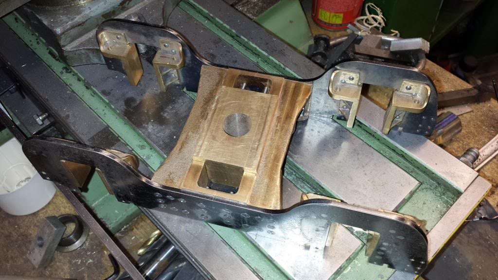
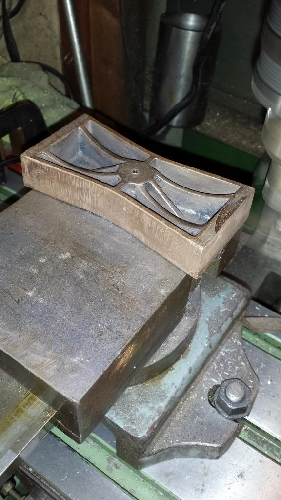
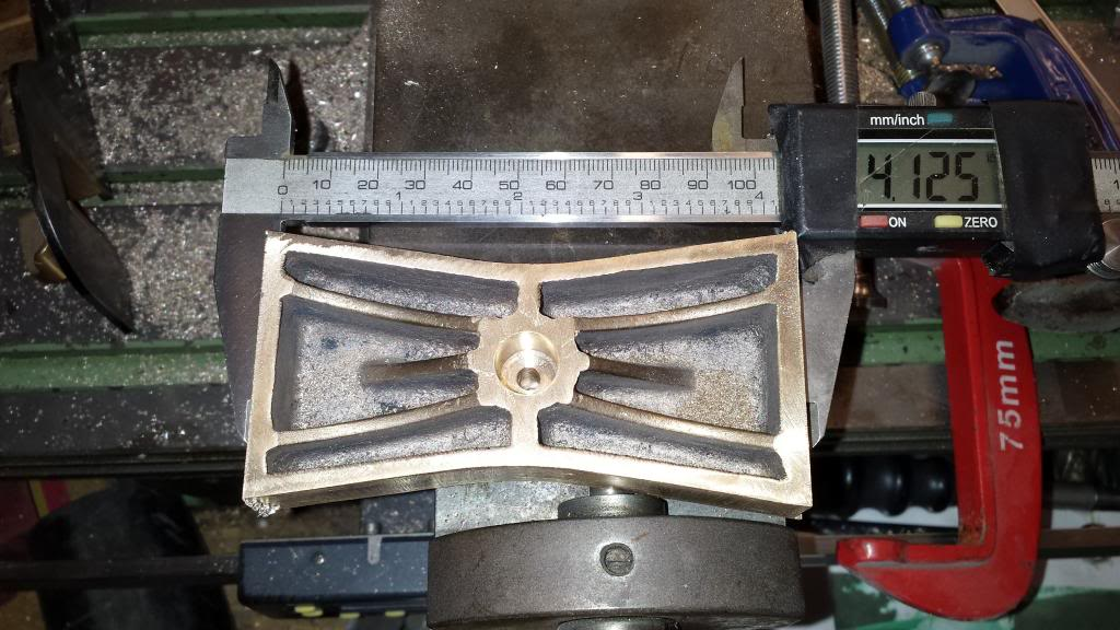
Fourth picture shows the underside structure, the 3/4 piece of silver steel is only there temporary. I needed to drill 4 holes at 7/8 PCD around the 3/4 hole, which were then tapped 8 BA ready for securing the retaining plate. I left the final operations on this piece until the bolster, pivot bolt and retaining plate were completed when I could assemble everything together to transfer the holes from the retaining plate to ensure all is square.
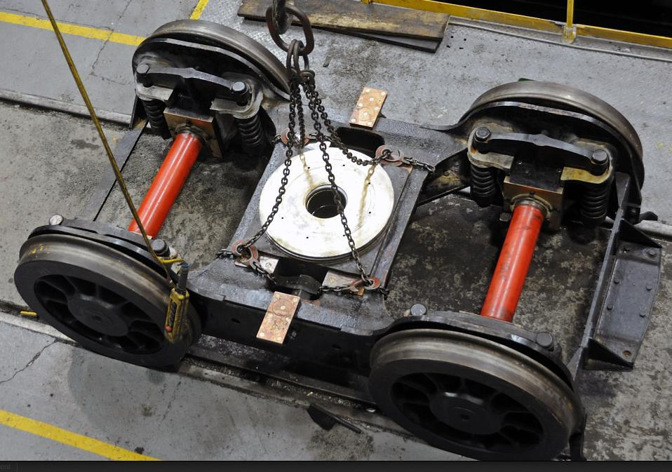
This picture is of the real bogie for comparison, it's strange as the way that the pivot bolt is slotted here is more like you would expect on a model, Don's design seems much stronger, this looks like how the bogie is held on my 3 1/2 4470...
NB: This is not the original picture used which showed the slot much clearer and didn't have the yoke fitted, alas I can't find it now and so have used the closest that I could find.
The next sequence of pictures show how I tackled machining the bolster which as mentioned previously needed to be modified for the side control bogie that I am building, as ,according to Don, the pattern maker who made the original didn't get chance to make the pattern for the later type due to work load, .
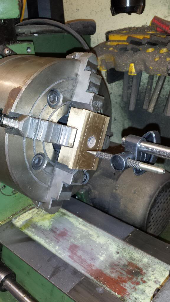
First picture shows the casting untouched already aligned in the 4 jaw, perhaps I should have started from the other side but this time it made more sense to start from here as i could see that because this casting had to be modified it was going to be close to get the 3/4 spigot to fit the yoke, there wasn't a lot of spare metal here. In hindsight I think it would have been better to make the yoke and spigot slightly smaller as the casting itself was very close to the final machined size with no real way of ensuring all was central for both sides. I chose to begin this side whilst trying to check what was happening the other end as shown in the following pictures.
Here is the bolster now modified to the later type, I thought that I had it central but I guess it wasn't although in my defence I don't think it was possible to get 3/4 from the casting as it was anyway, this isn't machined to size yet so most of the void will disappear but clearly it's slightly out, it's not a big deal as the spigot will work just as well but it is a little annoying, it was at this point that I drilled a small pilot to see how things where looking the other side.
Having removed the bolster to check ( only loosing the two jaws at 90 degrees of course) I could see that the hole was slightly off, I had a choice now as I hadn't yet machined the spigot to final size, I could try to realign or carry on as is.
I chose to carry on for two reasons, 1 I had no way of guaranteeing that the small pilot hole hadn't moved of line as it was a deep hole at 1 1/2" and 2 this wasn't the critical part, that being that the spigot was central to the casting when machined to size, so I decided to keep going.
This picture shows the spigot before final cut, not too far out, I forgot to take a couple of pictures but after this I machined the spigot to overall length of 3/4" and drilled the No.10 hole for the pivot bolt.
With that side of the bolster finished I'm left with this, not too bad...
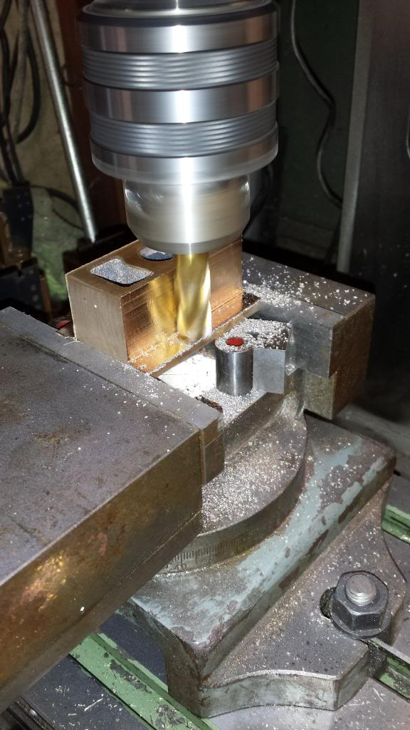
Before machining the sides and also the 1/2" recessed hole for the pivot bolt I needed to machine the top face down to the 3/4" finished size, here I begin with the fly cutter.
Bolster casting now to finished 3/4" depth
I seem to have forgotten to take yet another picture of the 1/2" recessed hole which I actually did 12 mm as I didn't have a suitable end mill to hand, not important and the depth was to 5/8th as to drawing which is important. Here I have set up the bolster in the machine vice to machine the ends, I could have used the rotary table but decided the vice was good enough since it was a handy size at 4" when I was machining down to 4 1/4, I trued the bolster up by using a suitable piece of square steel against the vice side to hold the bolster central in the vice and also square to it, I needed a second pair of hands here to tighten the vice while I held all in place, step in son number 3...
Once happy with the bolster positioning I fixed two clamps at the back to reinforce the bolster against possible movement and also very lightly fitted the red clamp as a warning of any movement as it would fall off if the work moved, I also rest a hand on the work while machining which is how I do all machining to feel if all is as it should be, keeping fingers out of the way of course. Before beginning I clocked from the centre of the bolster out to IIRC 2361 thou and began machining down in small steps of 20 thou just to be sure of no movement, this increased to 35 thou as it became clear that all was going to plan.
Now this setting on the DRO was for the overall size including the 1/16 lip that rests against the bottom of the main frames but I didn't cut all the way through, I stopped at the depth for the step to be machined next, this was just me being careful, it gave me a visual of where I needed to get too on the next machining step and also gave a neater cut for the lip.
Having finished the first cut I adjusted the DRO to 2299.5 ( I didn't have my notes in front of me so hope this figure was what I actually used, BTW I was using a 12 mm end mill for those who want to check) and machined down to the lip.
It was then a simple job of machining off the previous lip that I had left as a guide/reminder and then do the same again along the other side, I'm happy to report that the required 4 1/8 width between the frames was accurately achieved, thus I now had a bogie at it's correct width and also the first stretcher for the main frames.
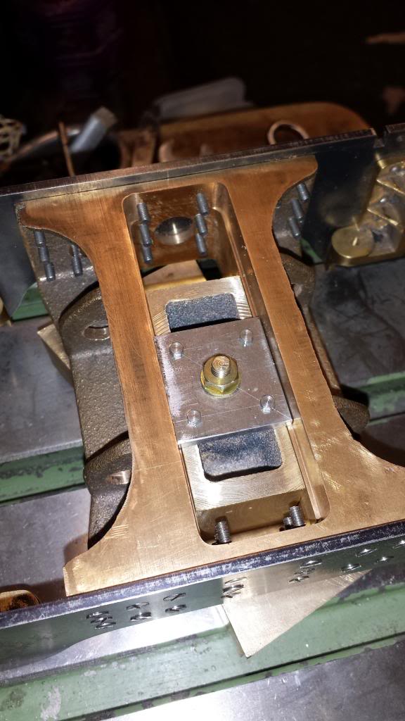
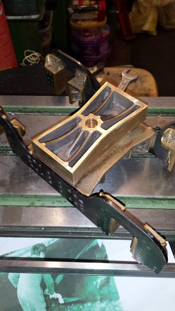
Final picture for tonight shows the finished bolster sitting on it's yoke, of course I still needed to drill and tap the mounting holes but will transfer these from the main frames as per usual when ready.
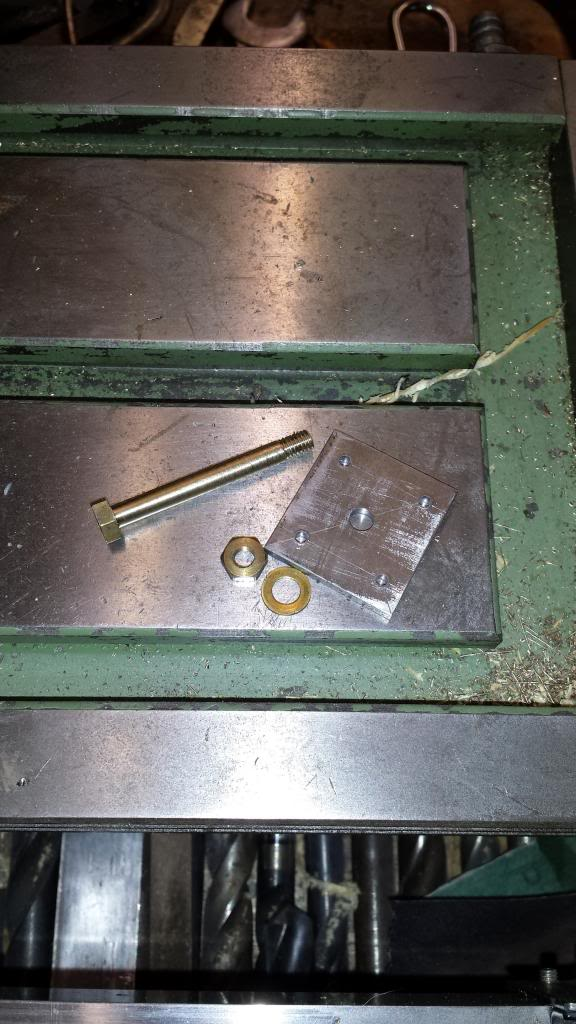
Here's the remaining parts needed for assembly....the bolt is 5/16 hex, machined to 3/16 to fit the No.10 hole through the bolster and finally threaded 2 BA, length from head is 1 9/16, I've added a washer. I will need to change this later as it should be steel but I had no suitably sized hex however I needed this part to fit the retaining plate to the yoke. Retaining plate has a central No.11 hole and the four other holes are No.44 ready for 8 BA bolts to attach it to the yoke.
NB: The bolt has now been replaced with steel as stated in the last paragraph
Bolster now fitted to it's yoke..
