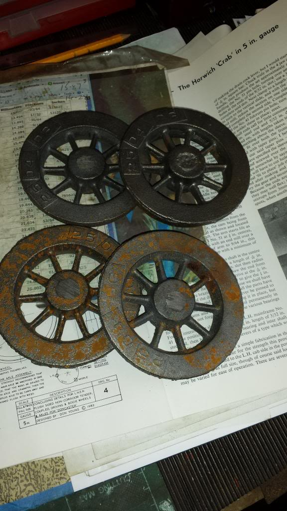
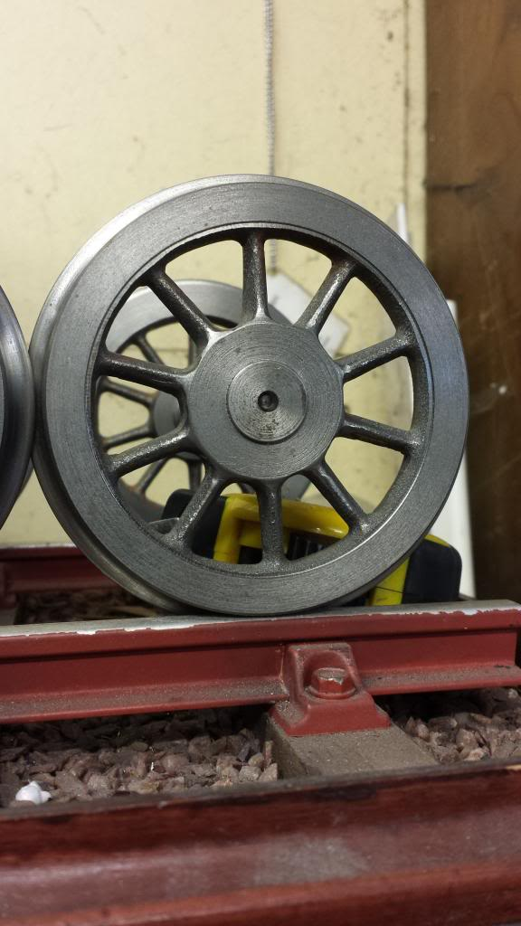
I was very much looking forward to doing these wheels, things begin to take shape when sitting on their wheels, even it is only those for the front bogie. There's a fair bit of work in machining wheels and not just in the machining, the spokes also need a lot of attention with a grinding wheel to remove the flash line. This picture is just to show the castings as come supplied by Reeves
First job was to machine the rear but first I had to decide how much to take off to keep the pattern near central to how the spokes where which seemed set back a little, I also had to take into account some pockets/dents in the bosses that I'm assuming happened during casting, no big deal as long as your aware of it before beginning to cut. The castings have a lot of extra metal in them so there is some maneuvering room here. Once happy with how they sat in the 3 jaw I machined the rear down first, iirc by about 3/32 and then the boss was machined to 1/16 proud of this, picture shows boss and wheel being rough cut using a carbide tipped tool. Once I was happy with the roughing out I used a vernier to check the thickness of the casting so that I could later get the other 3 wheels the same size for this stage. I also roughed out the overall wheel diameter to over the required size of 3 11/16 or 3.6875
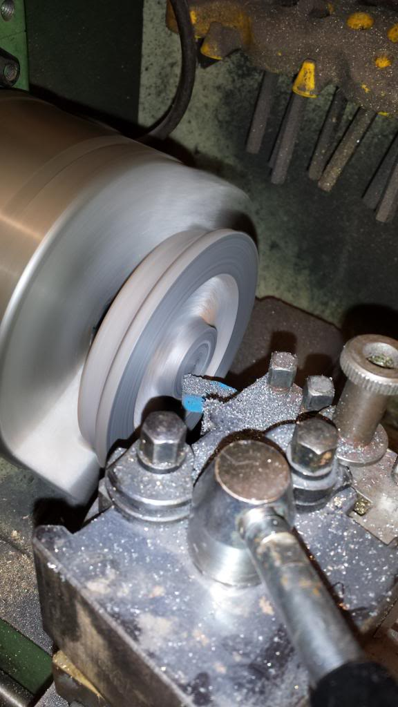
Next the tool was changed to an insert type and the back face was finished as was the diameter , being machined as shown here.
Using a hand file the 3/32 rad profile was added to the back face as to 5" wheel profile standards, to be completed once the front tread was finished.
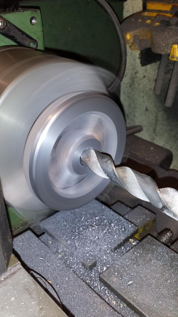
On to the 5/8 hole for the axle, here I followed standard procedure, first centre drill, followed by a number of drills( about 8) up to 39/64 or 0.6094 as shown here.
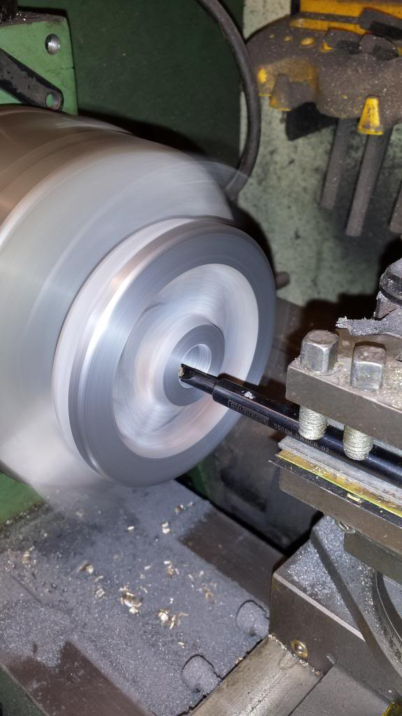
Then on to boring until a few thou under 5/8 0.625, final job was to ream out but I seem to have forgotten that picture.
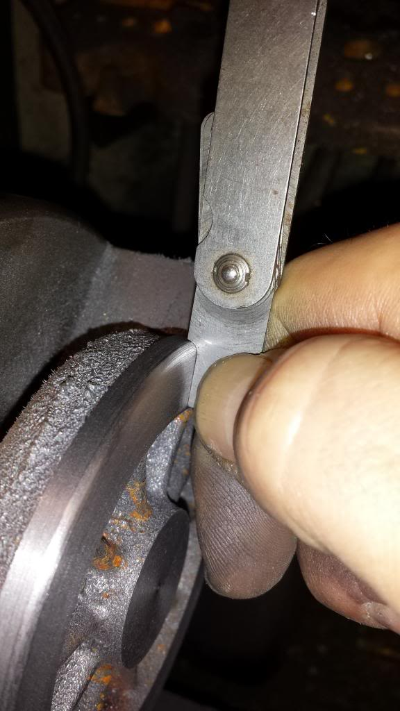
Here the axle is checked for fit, these were a tight fit.
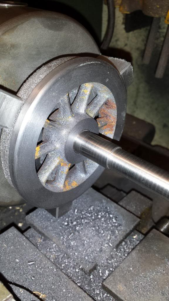
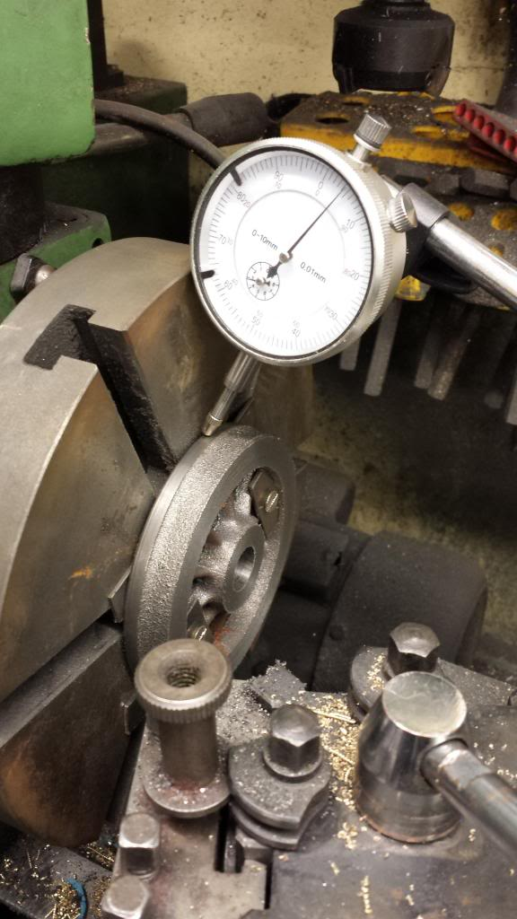
It was then time to do the fronts, the next picture shows the first wheel having been clocked to run true, the wheel is spaced off the back plate by two 1/16 strips of steel which is the same depth as the rear centre boss is from the wheel tread thus holding the wheel true to the backplate. The wheel is held tight to the back plate via two 2 BA bolts and plates through the spokes, these are the same two holes that were drilled and tapped to hold the tender wheels through the two anti ringing holes in the wheel discs and would also be in the right place for the trailing wheels when I got to then, I will probably use another method for holding the much larger driving/coupling wheels.
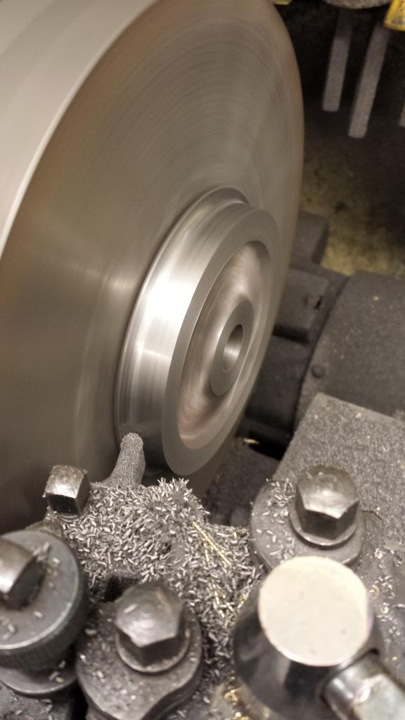
Second front picture shows the tread being cut with a profiling tool but before getting to this stage I first rough cut the tyre, boss depth and tread with a carbide tool. I then set the top slide to 3 degrees ready for the tyre but first finished the tyre, boss depth to 1/2" + 1/32 respectfully, I then machined the tread but leaving it slightly oversize until all 4 wheels were at this stage, the 4th wheel was then cut to final size, cross slide set and then the other 3 wheels were refitted to the mandrel for their final cut to size. This left two jobs to do, the inner 3/32 flange curve that was done the same as the back curve with a hand file and the 30 degree chamfer which were all done in turn as per the other operations.
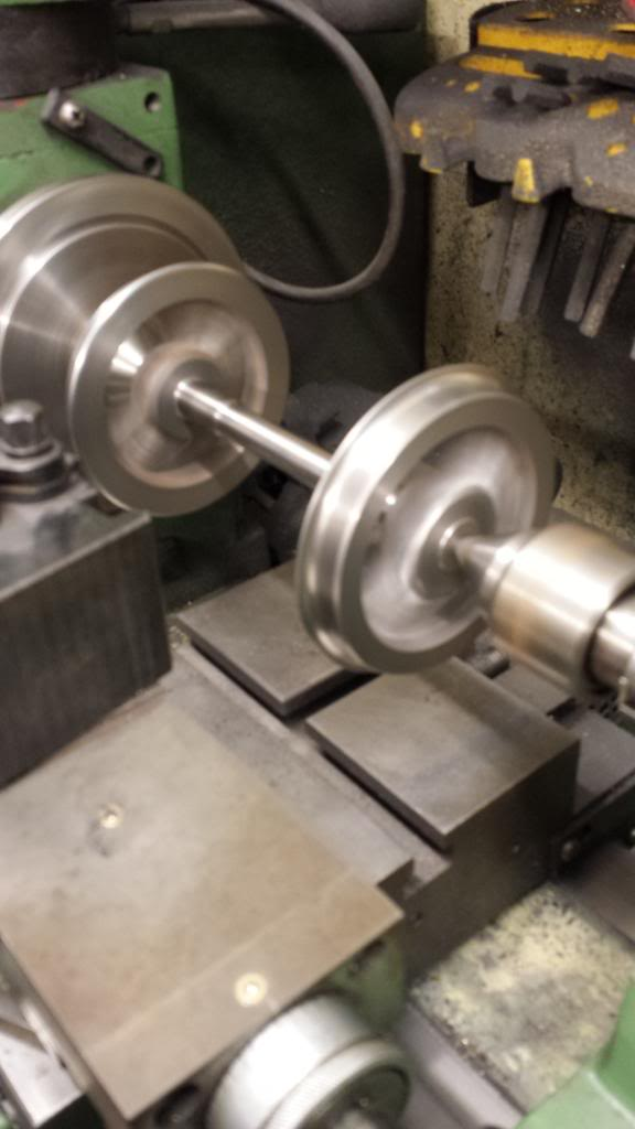
Final job was to dry fit the axles and run the wheel sets between centres to check that all was as should be. All was good although one chamfer had a very slight wobble which was easily fixed with the hand file, perhaps I hadn't tightened one of the wheels properly during that stage, no big deal.
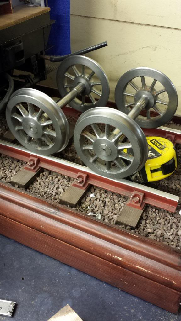
This picture shows the near completed wheel sets, although there was one omission which thankfully someone pointed out, I hadn't yet machined the tyre inner lip.
Before machining the missing lip, I decided to first fix the wheels to their axles using Loctite 638 ensuring that the all important back to back measurement of 4 11/16 was maintained and then to cut the lip while the axle was held between the 3 jaw and live centre. Using photo's as a guide I set the cross slide to give a suitably sized step and machined the step taking note of the dial readings for the other wheels, it was then a simple case of machining each wheel in turn to these settings. One small confession here, I had already stated that the wheel to axle fit was very good, in fact I could possibly have got away with leaving them as a drift fit but didn't want to risk a wheel becoming loose on a tight curve so decided to use the Loctite just for extra insurance. Of course this meant that with a non existent clearance that I had very little working time to get the wheels to gauge, well in fact I had next to no time. I dry fitted first to take note of where the wheels sat which was at the correct steps as cut in the axle, trouble is you can't see this step very well when fitting the wheel from above. Anyway I got the first axle set correctly however the second was a fraction out, it was slightly smaller so rather than heating up the axle to 250 c to release and do again I just trimmed a very small amount of the back of each wheel (around 5 thou each side), of course know one would ever know, well except for you lot now...
this picture shows the step being cut, I used a small boring tool as it was a handy size to get in close to the wheel while using the live centre.
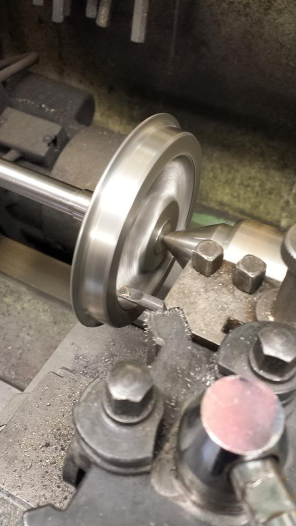
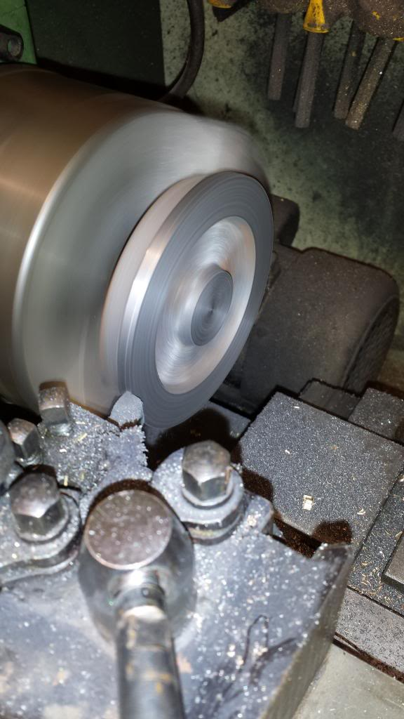
And a close up picture to show the completed step/lip cut into the wheel face.
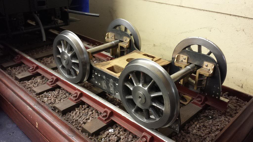
And here we have the bogie resting on the completed axle sets... of course an important part is still missing, that of course being the axle boxes