
I'm now returning to the motion and I'm going to start with the 2:1 gear for connecting the valve events for the middle cylinder, before doing so I need to finish the gear stay which involves turning up the fulcrum bearings and their pin. I have again deviated from Don's design, Don shows plain bronze bearings which protrude through the stay upper and bottom faces leaving a 7/16 gap between them for the 2;1 lever to fit in. He describes brazing a small web up against the top bearing to hold in place? I don't like this idea and in place will machine larger stepped bearings with wide flanges to sit tightly against the upper/lower faces. These will retain the 7/32 size reamed holes for the pin. I will also leave a larger opening between the two bearings, I've done this so that if the need arises I can fine tune the height of the 2:1 lever with suitable spacers.
The bearings are a drift fit and will be further secured with a Loctite retainer.
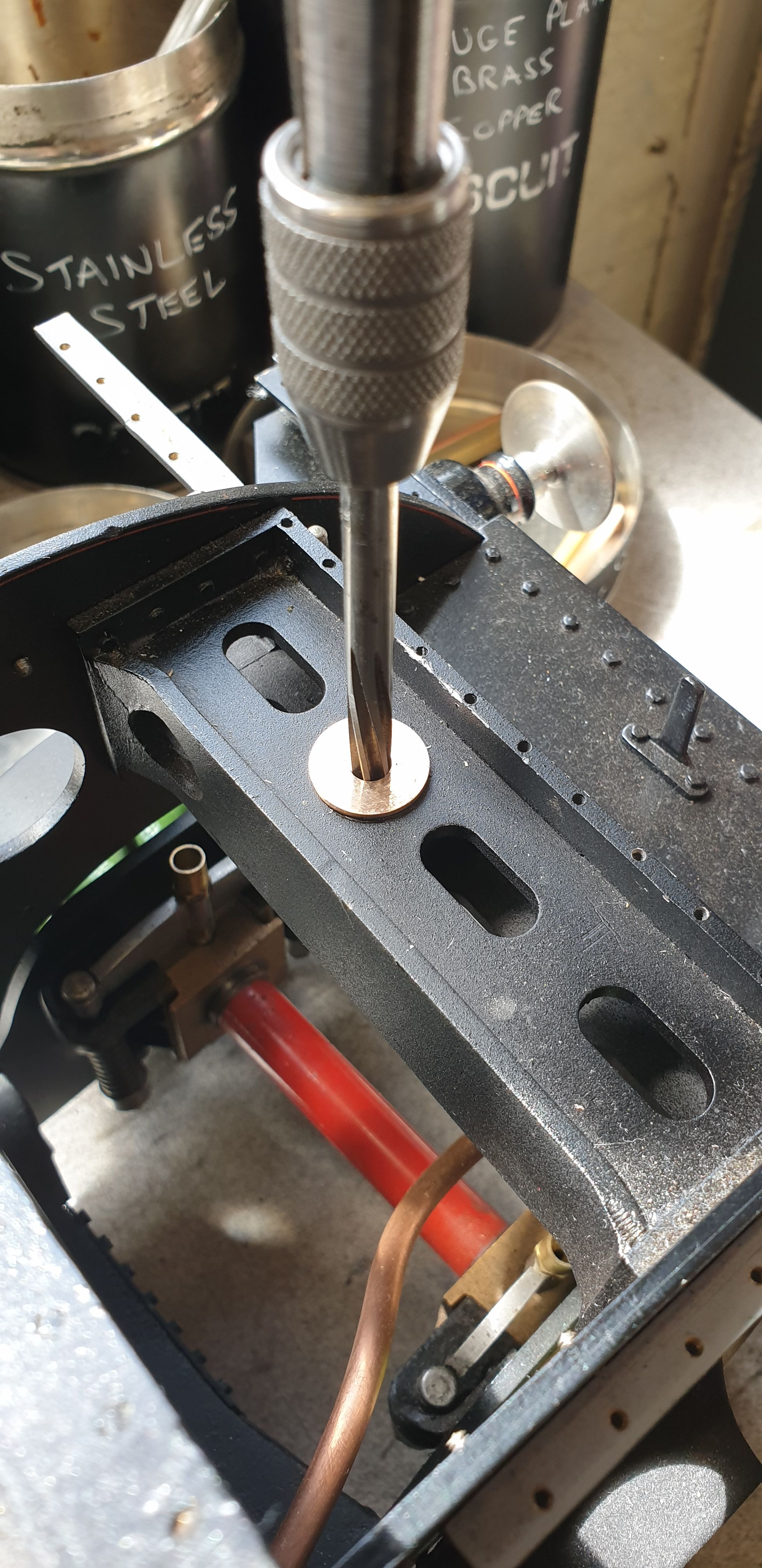
A little background on the position of this fulcrum pin, this has to be accurately placed at 1 17/32 from the left hand inside edge of the frames. This was described some time ago, it was basically achieved by mounting the erected frames on to the milling table and using the DRO to plot the position of the hole which was then drilled to size and reamed 7/16th as per drawing.
The first picture shows the bearings in place and reamed to 7/32nd. The lower bearing was fitted first and pulled tightly into the hole using a 'G' clamp and piece of wood to protect the stay. Once happy with that the top bearing was drifted into position using a small hammer, as mentioned both bearings are secured with Loctite. The final job was to ream through the two bearings together now that they are in their proper position.
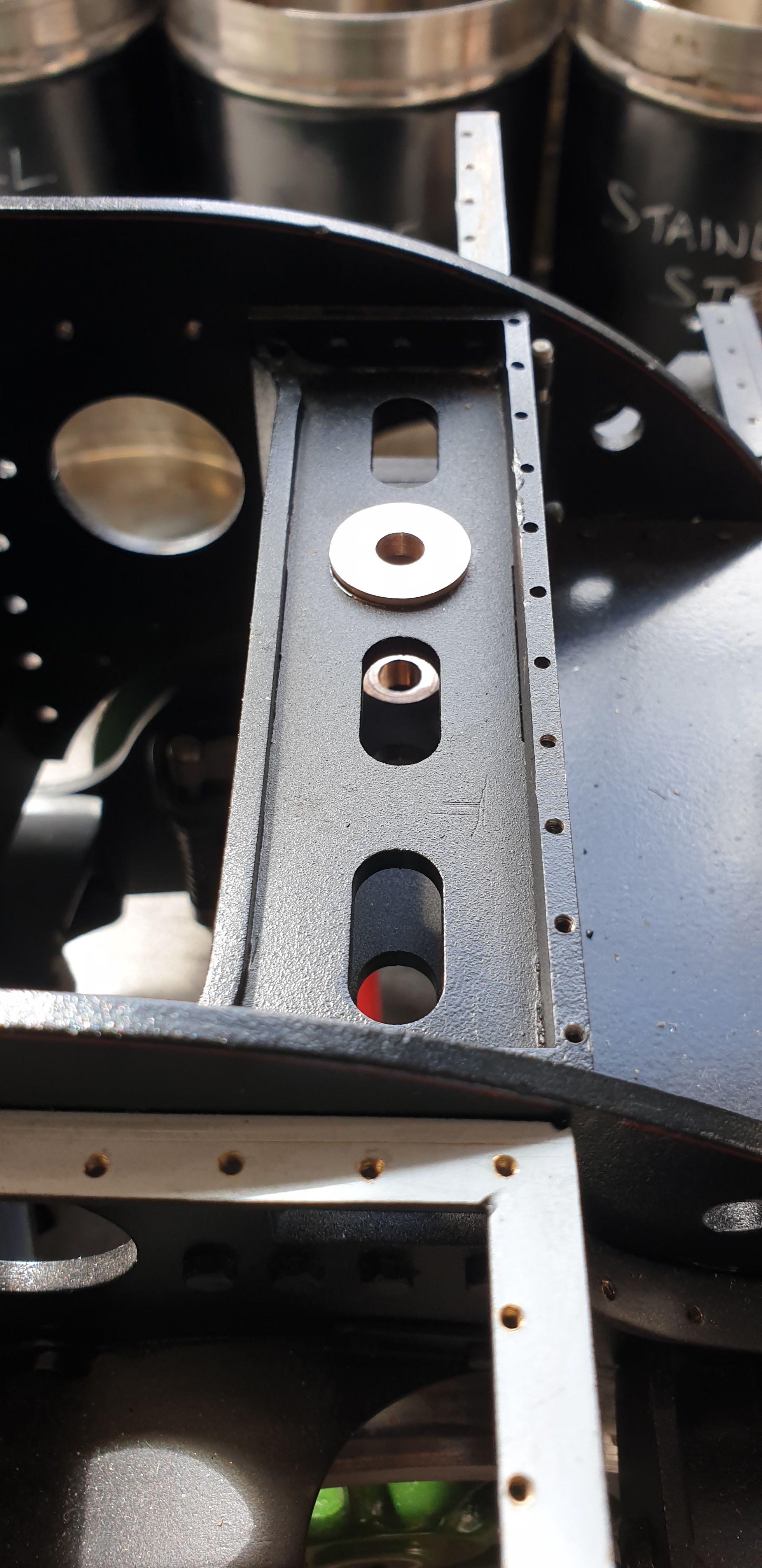
I've included this picture to show both bearings, the 2:1 lever will be held in between.
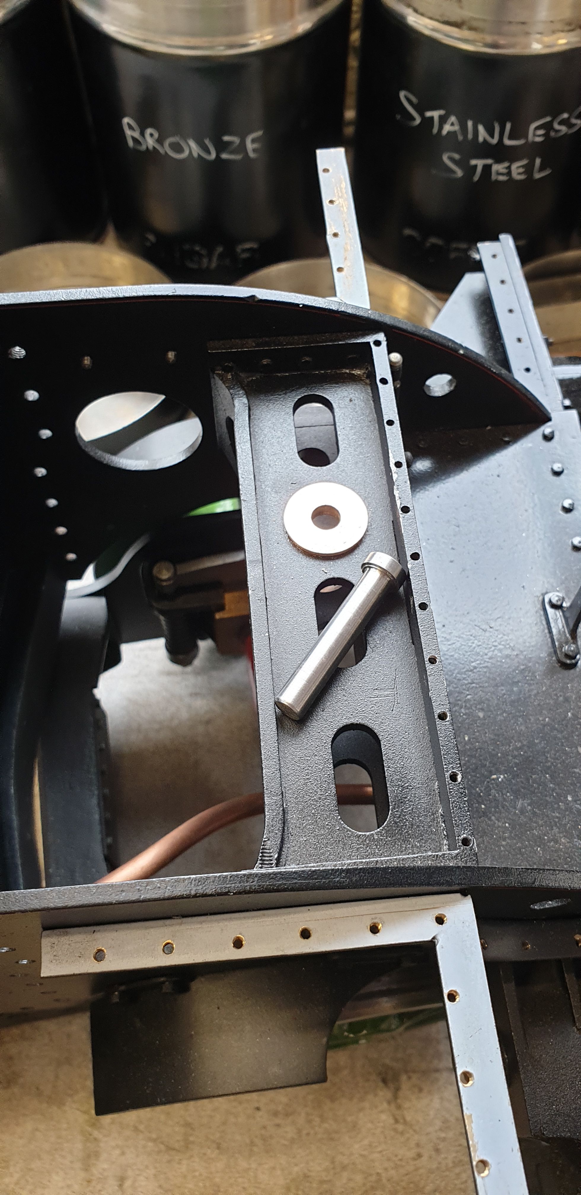
Last turning job was the pin, this is made in stainless steel, I still need to cross drill the end for a split pin to hold it in place, this will have to wait as the 2:1 lever is currently set up of the mill. Note the small step, in fact it's much smaller than it looks in the picture, this gives a 'snap' action to the pin as it's pushed fully home. This will help stop it from riding up in the bearing, the split pin (probably an 'R' clip) doing the rest.
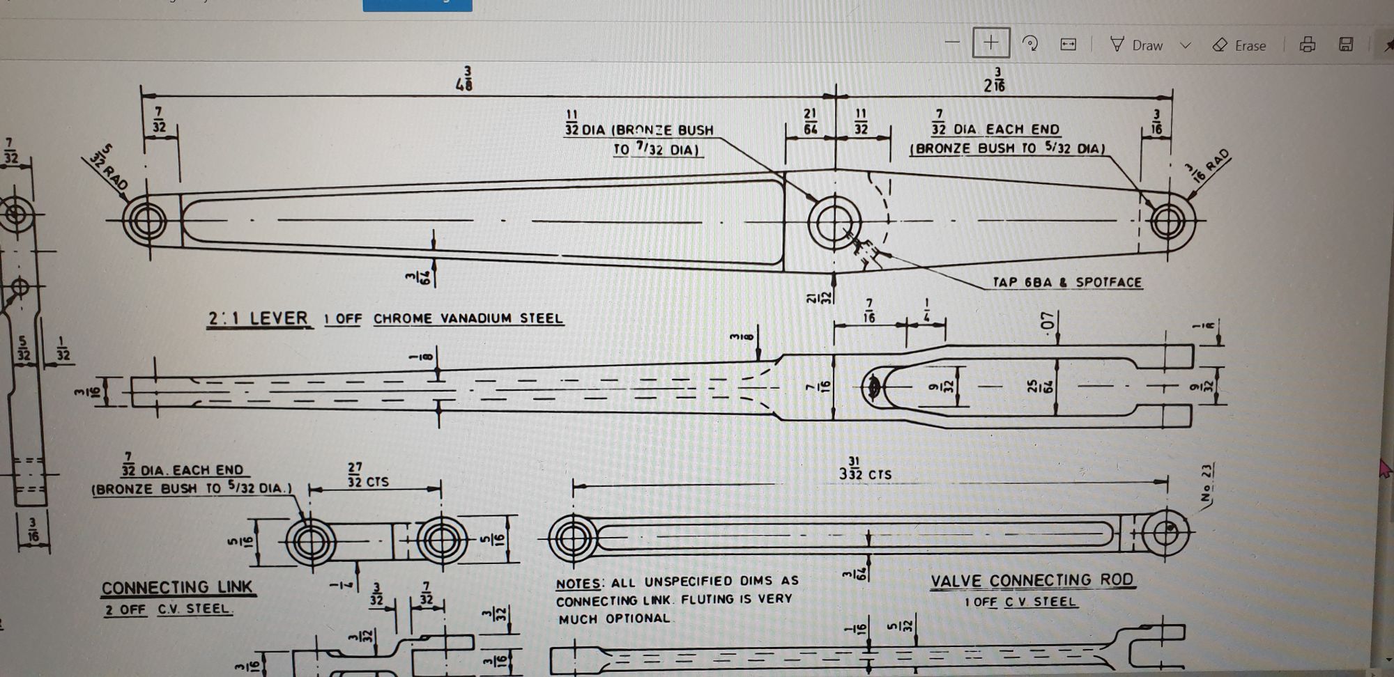
Now I can give my full attention to the 2:1 lever, this is pretty involved and will take a good few setups, again I am going my own way in how I machine this part, as the saying goes there are 'many ways to skin a cat' this lever is my way.
First I'll show the drawing so you can see what I have to make, plus it should hopefully, help with understanding my approach in machining this part.

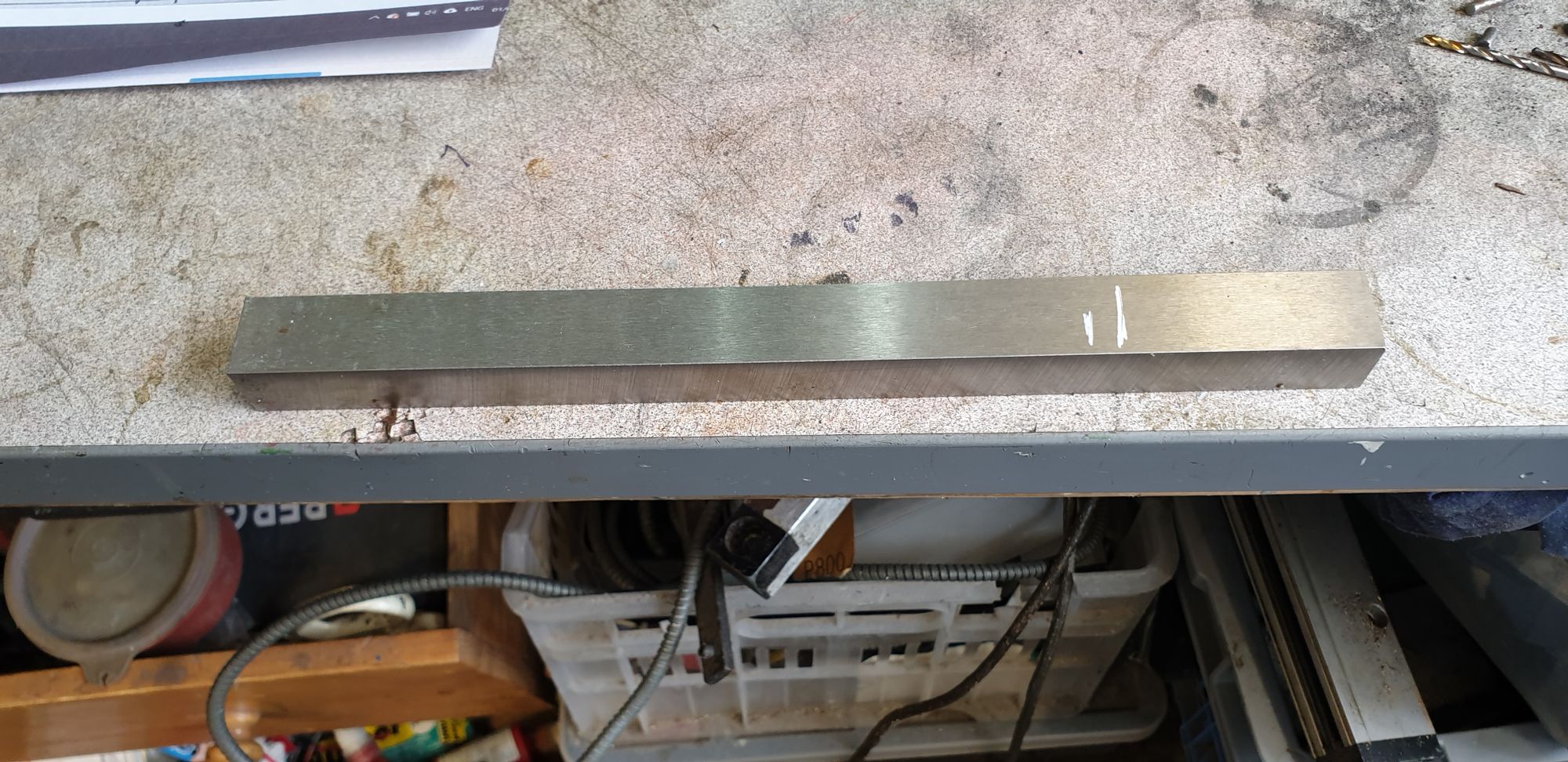
As with all of the motion on this model except for the coupling/con rods which are HROP this lever is being machined in gauge plate. It starts life as a 9" length of 3/4 x 5/8 plate, not sure why I ordered 9" but here it is before I cut it down to just over 7" in length.
I don't usually show a picture for setting the job so will include one here, I use either this LED edge finder or a mechanical variant depending on the part being set up, a big lump like this warrants the LED type.
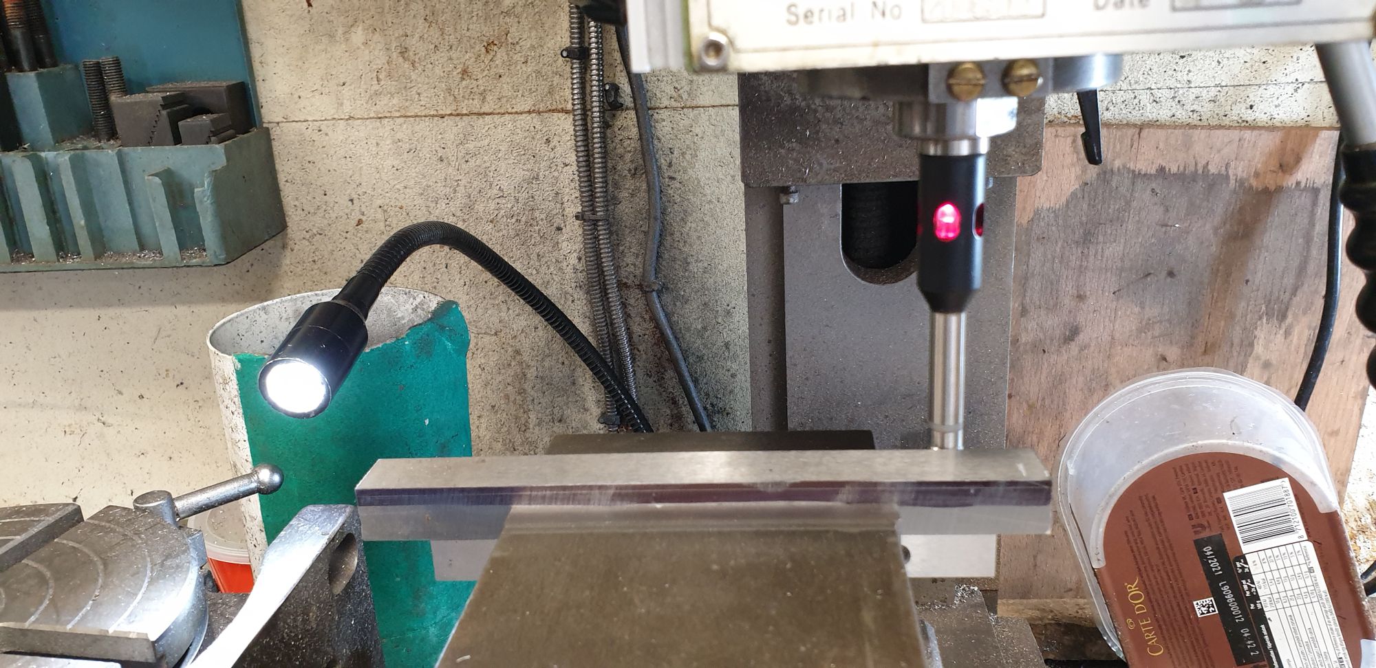
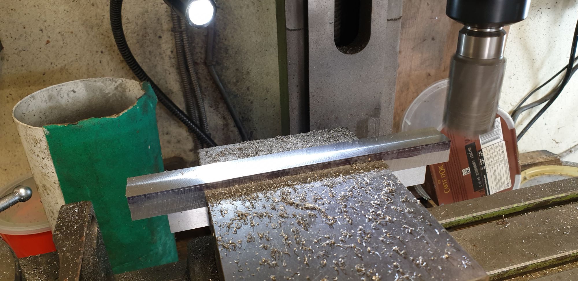
I tackled this job starting with machining the 5/8th down to 0.531 which if looking at the drawing for the fork end is 9/32 + 2x 1/8th. I used a large cutter for this, holding the work in the machine vice which BTW is where all of this part will be accomplished except for the end radius's. You can see that I've ascribed a line to give me a visual as I cut metal.
I then drilled and reamed the three holes, measurements and sizes can be seen in the drawing.
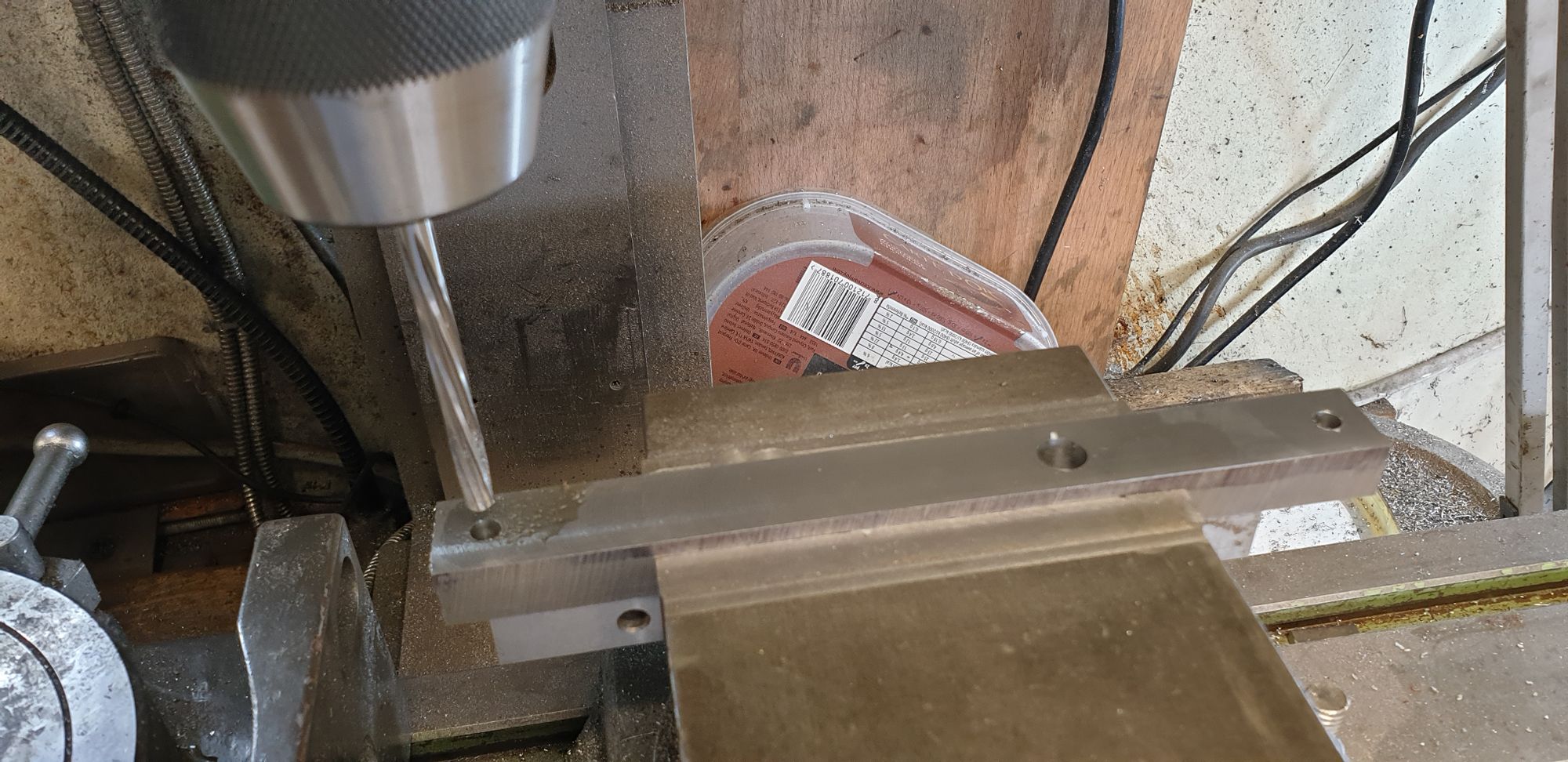
Next I reset the part on it's other axis to chain cross drill the holes that will eventually be opened up to the 9/32 slot for the 1:1 lever The hole furthest in is where the slot ends, this isn't as straightforward as it looks as it needs to arc around the fulcrum pin hole (as per drawing), I have an idea for accomplishing this but will have to wait for now.
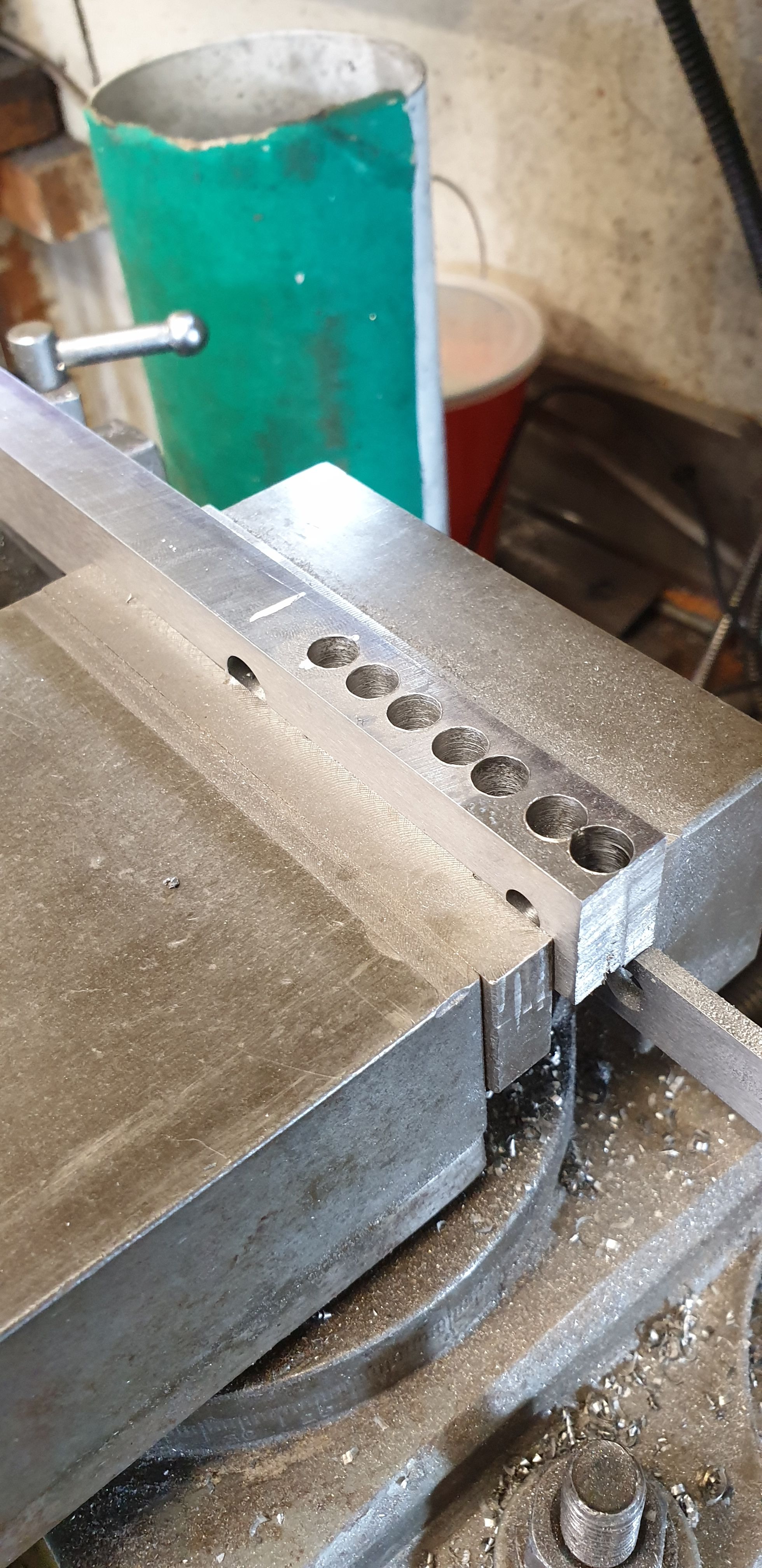
While the part was set in this position I moved it further along the vice and machined the 3/16 wide tab for where it connects to the right hand cylinder.
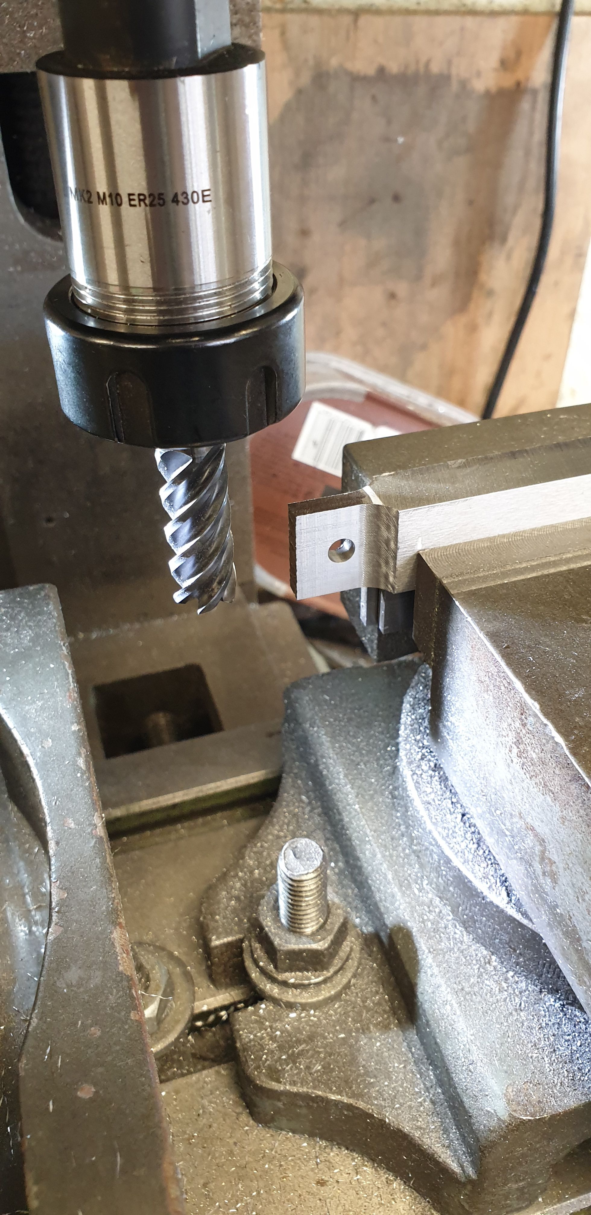
I had a forced break soon after this as the mill decided it didn't want to play ball anymore and packed up just as I was reducing the rest of that tongue side of the lever prior to tapering it overall. Oh well, now is as good a place to take a break as any, The offending parts have been ordered (playing safe with new motor and speed controller board) and so hopefully play will resume very quickly.