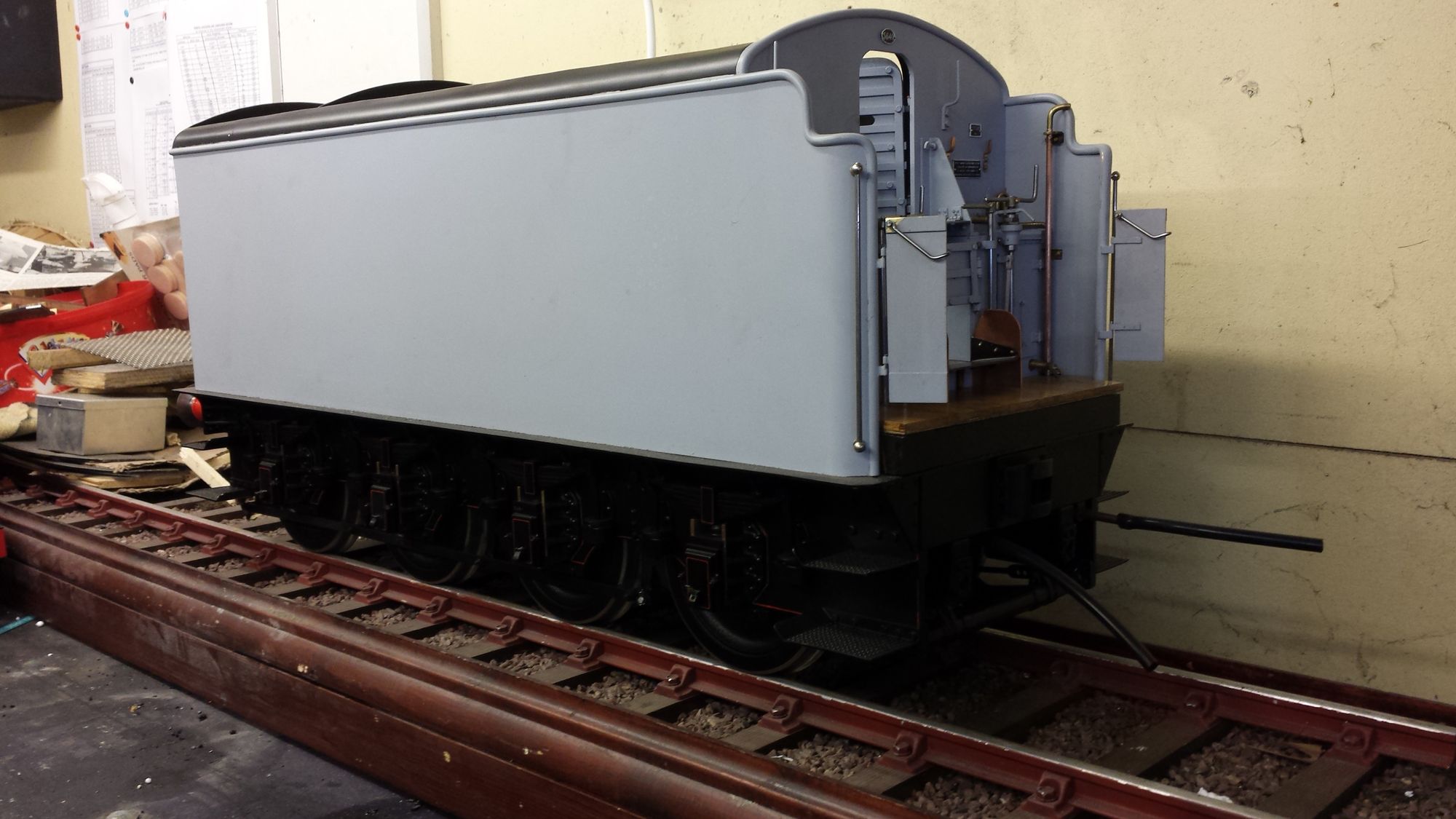
The tender on a Gresley pacific is a pretty large affair, with it's 8 wheels and large capacity it's an impressive sight in its own right. It's also a fairly large amount of work to build in model form, perhaps as much as building some small tank loco's.
The model has most parts working, water gauge, handbrake, vacuum brakes etc etc, the exception being the scoop, I have followed Don's advice here and left it off for safety reasons. Once completed the tender will be full of detail, including it's lockers with their white painted interiors and wooden floor pallets which will be full of the correct tools. The front coal wall is highly detailed, there will be no removable section on this model. Also no hand-pump, the boiler will be fed as per prototype with two injectors.
The tender was where it all began and i'm glad that this was the case, starting with the locomotive wouldn't be the best way in achieving my goal, tenders left till last tend to get rushed a little. This tender which actually isn't fully finished yet took a couple of years to get to the near finished stage that she is today. The thought of spending approx 10 to 15 years building the loco to then have to spend a further 2 to 3 years on the tender doesn't really appeal to me, this is where things could get rushed.
The build begins:
As I stated in the beginning, things may be a little sparse on details to begin with, that's because I had already done some of this work before actually writing anything about it and thus I have more or less just listed the parts made to begin with, as we progress I'll be giving greater detail into how I approached the parts as they were built.
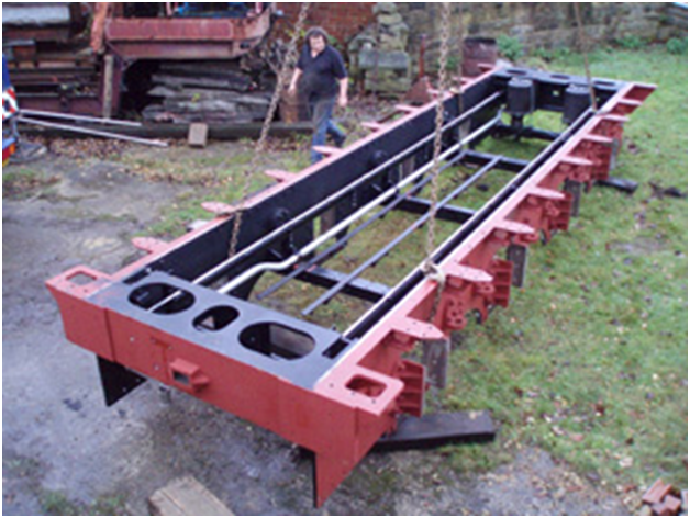
Tender frames erected, axles turned, horns fitted, axle boxes being constructed
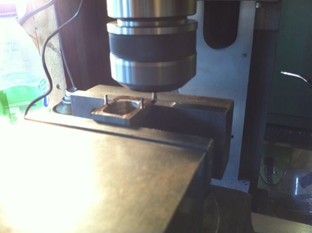
Axle boxes well advanced having already been bored out, tray recesses machined, here the concave edge to top and side of the box is being machined. Stubs for covers having previously been drilled and tapped for 10 BA studding
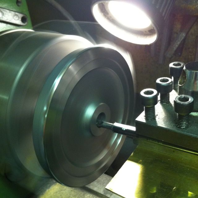
The first tender wheel having the back machined and then bored out
Trial fit of wheels onto axle before machining the fronts
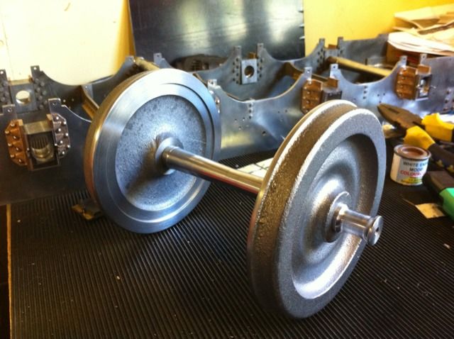
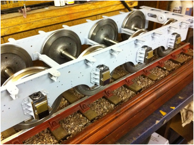
A rolling chassis at last, seems strange getting to this stage already in this thread when in fact it took many weeks, makes it look so easy.. Yeh right?
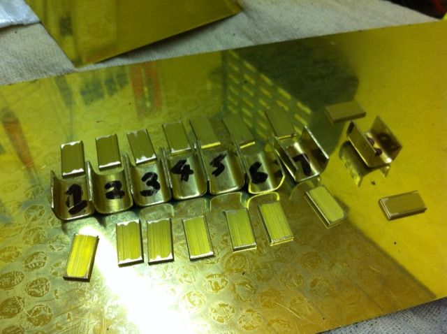
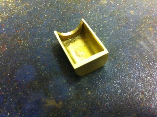
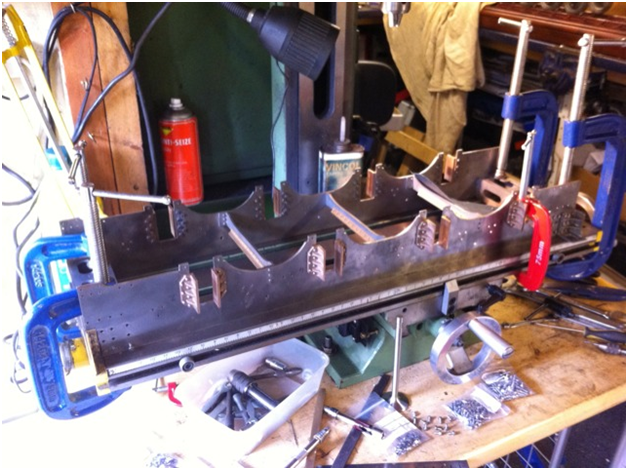
The eight oil tray components cut, formed and now ready for soldering
First tray brazed together with rear panel shaped to clear axle
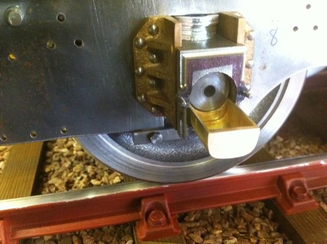
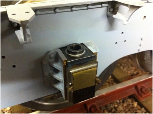
Test fit of tray to axle box making sure it's a good fit for the axle, I still need to make the oilway blocks which will then fit through slots in the covers when machined later
Tray in place, the washers above the box are just there tempoary holding chassis at correct height
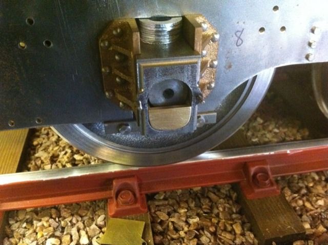
Cover put loosely in place showing marking out for oilway block to be machined later
So far the chassis had been temporary held together with mostly oversize head bolts and screws. I used these because during this time the chassis was dismantled many times thus marking the heads, it has now reached the stage where I could use scale sized heads for which I used Loctite to secure.
In this picture the chassis is held square on the mill bed while I changed the bolts. I was very happy that the chassis remained true with no rock.

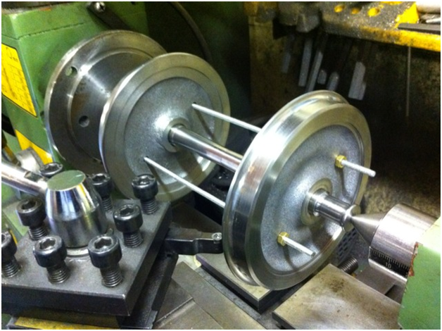
Now that I was happy with the chassis it was time to Loctite the wheels to their axles. Here I have set up one of the axles between centres and used the toolpost to check alignment. These wheels have two small holes that don said were there to stop the wheels ringing. When it comes to building the model they are perfect for holding the wheel onto the faceplate (alas I have no picture of that stage).
I wasn’t sure if these were supposed to be inline across the axles or not but decided to do so anyway, hence why there is studding being used to help align them. I was amazed at how quickly the Loctite set, luckily for me it didn’t catch me out.

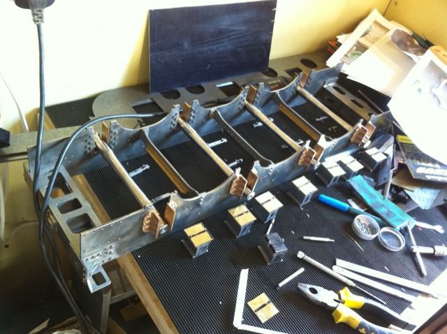
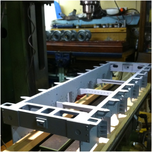
The chassis now had the outriggers brazed up and attached using 1/16th rivets to the frames. The ¼ x ¼ x 1/16 brass angle has also been riveted inbetween the outriggers. I then sprayed the chassis with Upol acid 8 etch primer.

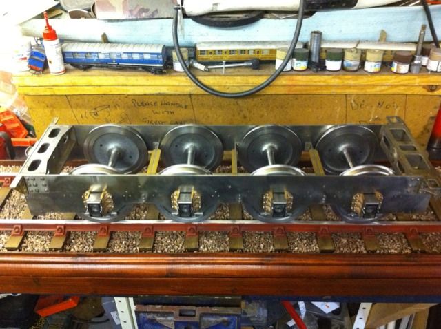
The chassis at that stage, in the background you can see the wheels with axle boxes fitted awaiting refitting to the chassis

A picture of Tornado’s tender chassis at a similar stage which I have used for reference.

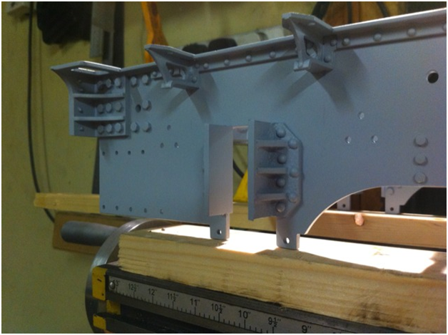
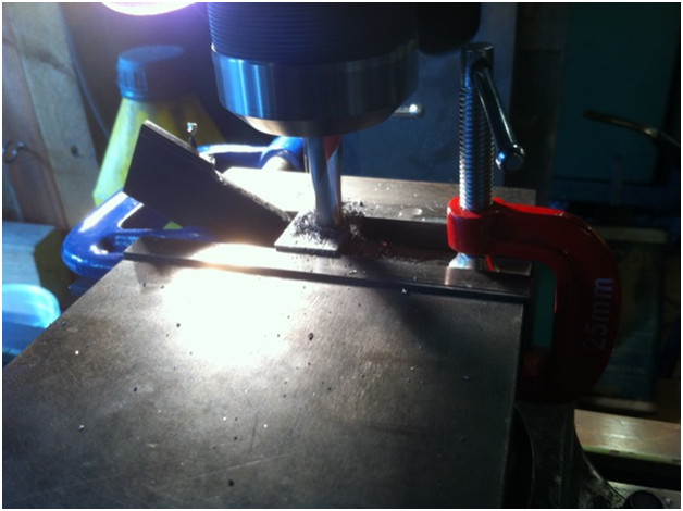
Spring Plates, naturally there are 8 of these, 4 intermediates with extra allowance for axle movement and the lead and trailing plates which have less movement. I gang machined these in batches of 4, here the intermediates are having their slots machined.

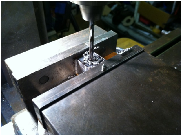
The plates have rings brazed to them for the spring buckle to sit into. I decided that an easy way to ensure the rings went on centrally and also to hold said ring while being brazed together was to drill holes into the plate for temporarily holding the rings in place using bolts. Here 4 of the plates are being drilled together for this.

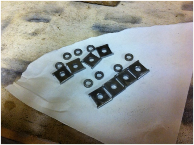
Plates and rings ready for brazing, the rings were a simple turning exercise. the parts were held together using 8mm bolts/nuts

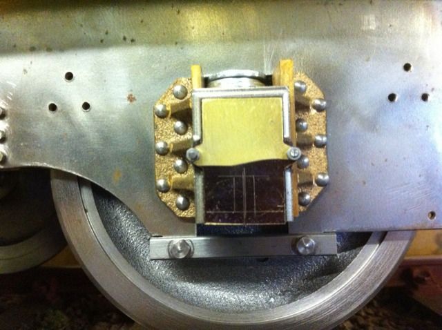
One of the finished spring plates in situ.

Starting to look the part, next I’ll make a start on the body.