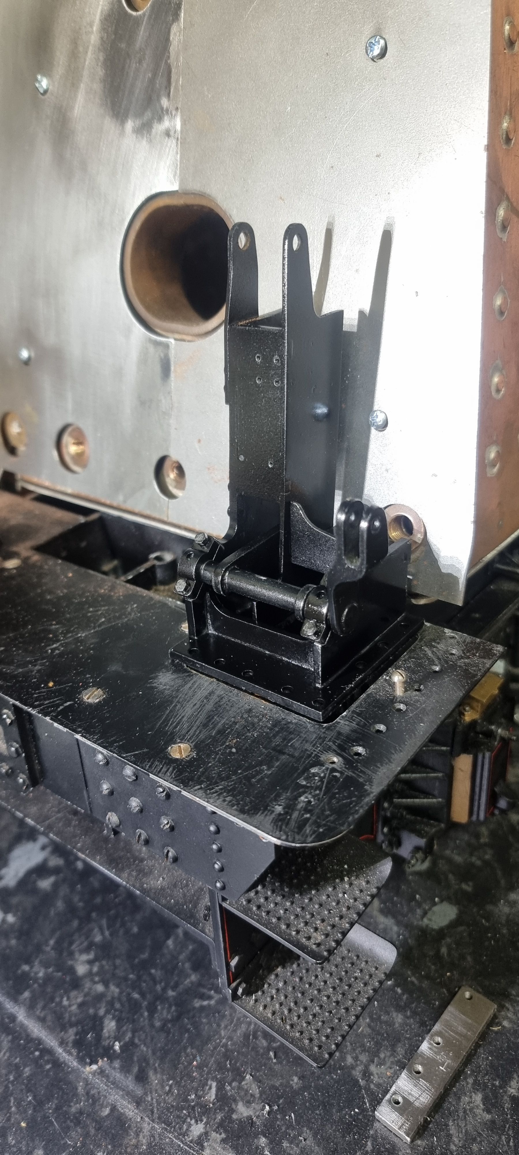
In this update I'll cover the fabrication of the reverser shaft including the extra checks that I took when assembling the parts thus ensuring no issues further down the line. This will be nothing new to most of you who probably do the same checks but is worth pointing out to those new to the game, Don gives some dimensions to check on his drawings which I'll also cover in the upcoming text.
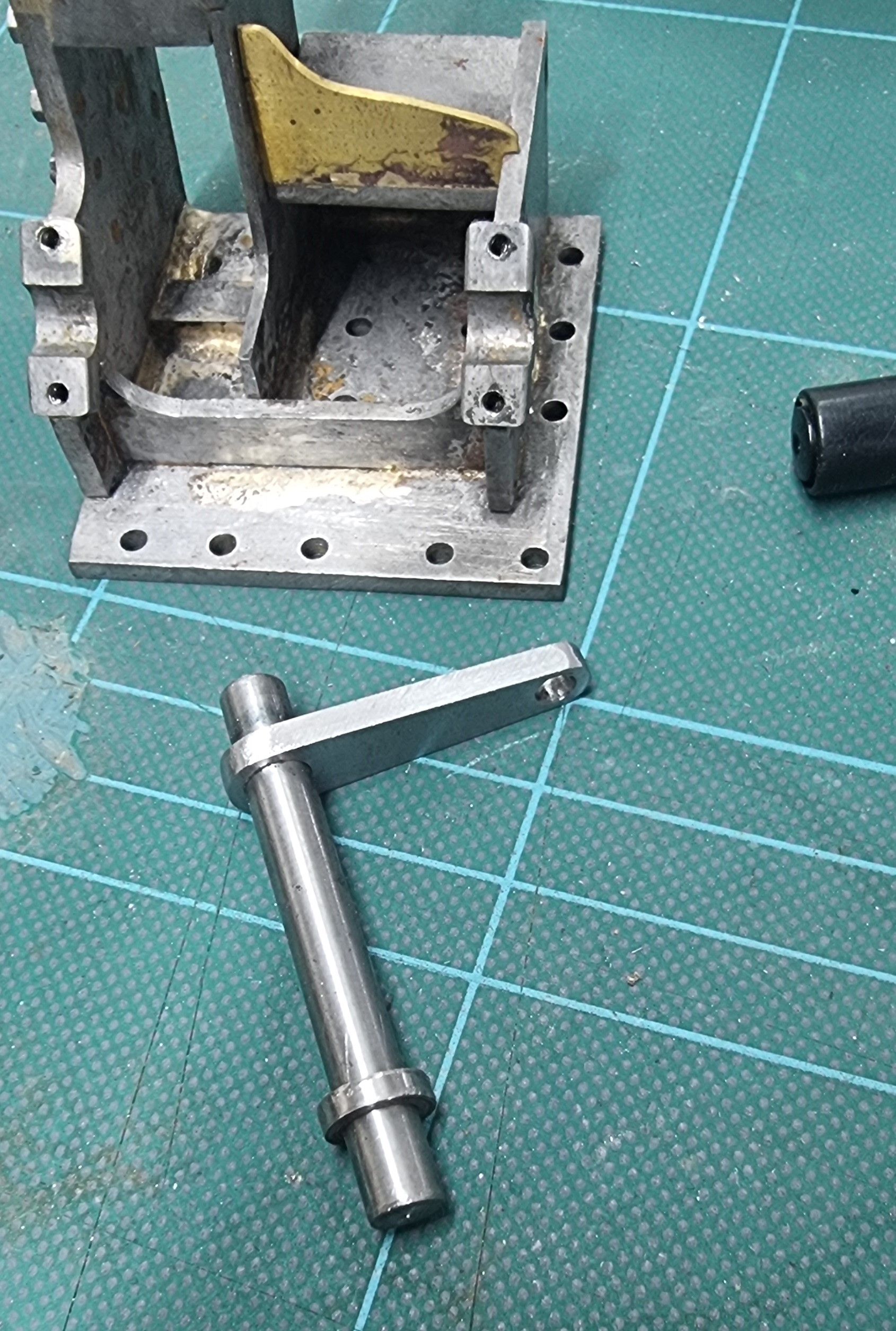
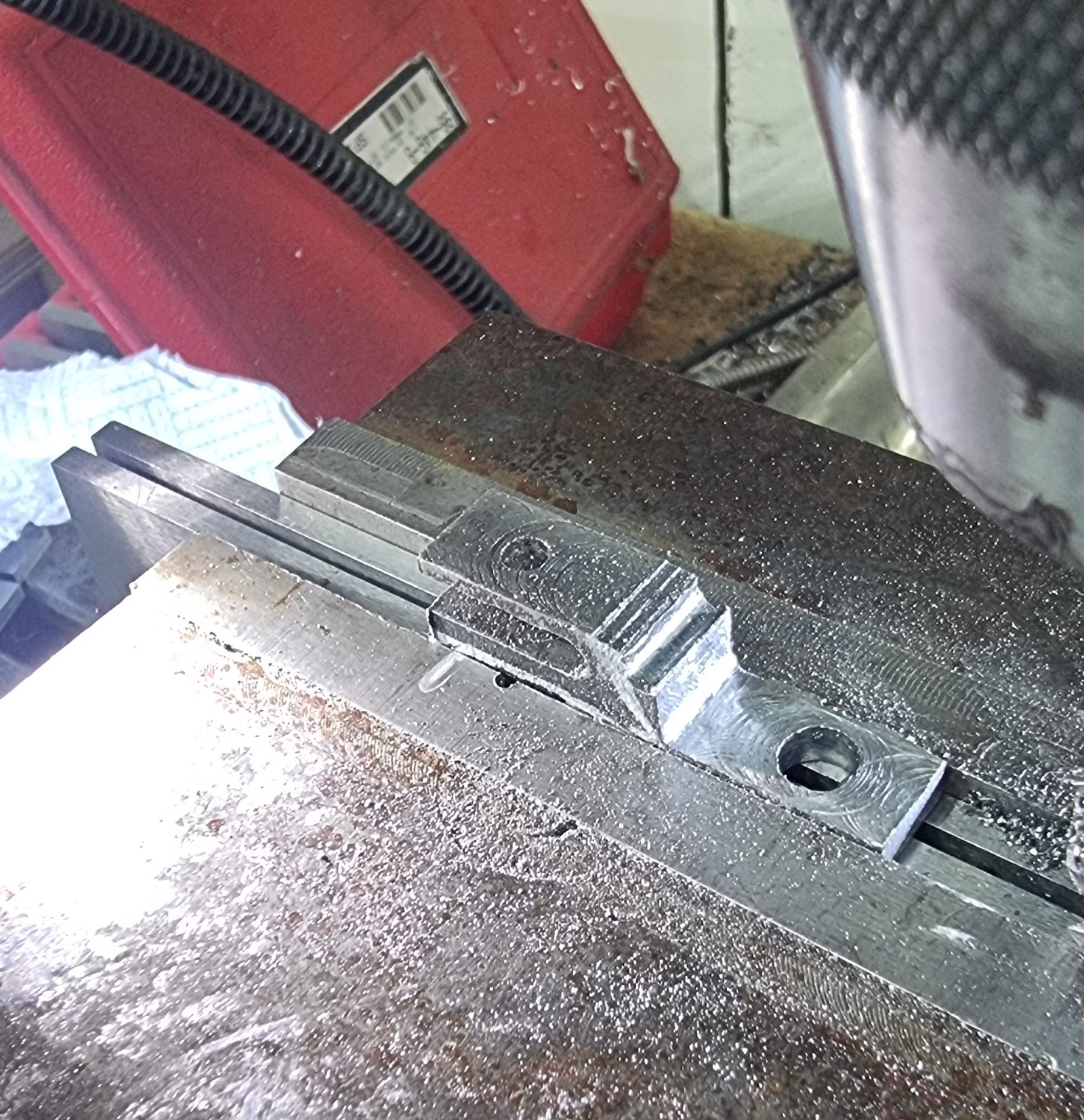
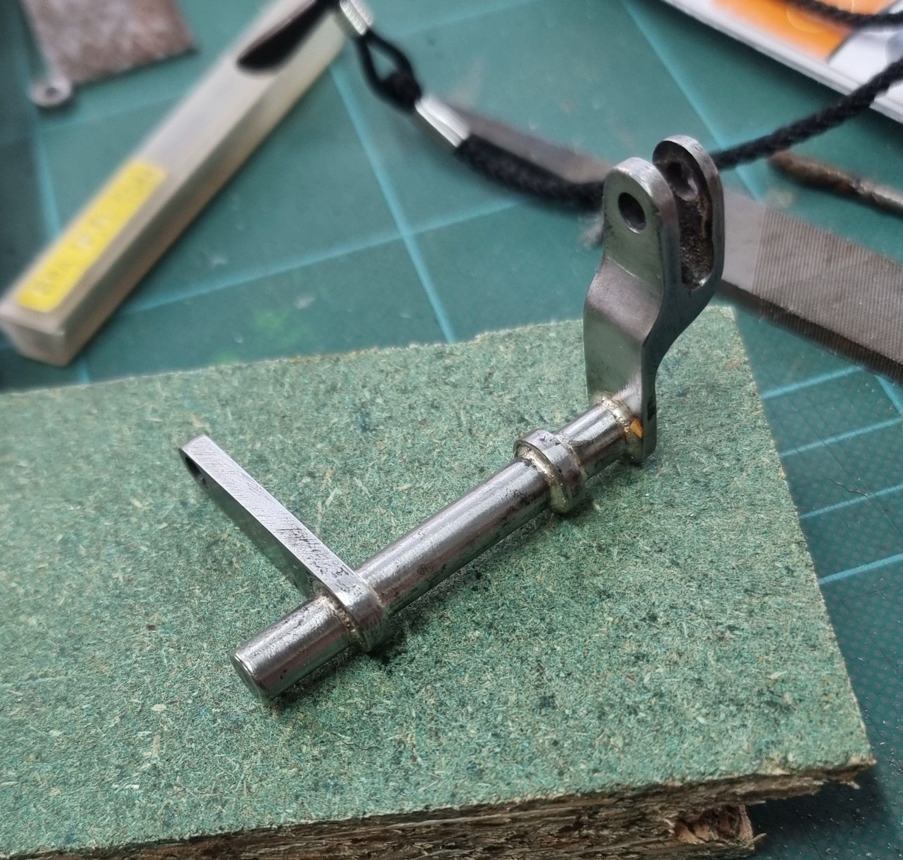
Following Don's method of construction the reverser shaft comprises of 4 parts, a 2 inch length of 1/4" steel rod, a 3/8 x 1/8" length of flat bar to make the arm, a 3/8 dia collar and a length of 3/8 x 1/2 for the fork. The first job was to make the arm that will connect to the reverser screw, which is as mentioned a 3/8 x 1/8 flat steel bar, this has two holes, one of 1/4 and the other No.23 dia, which have 1 1/16 centres. This is slid over the 2" 1/4 steel bar, drawing says to mount it 3/8 from left side (will be the right side for an A3 or A4), I left the final position until the other parts had been made and after trial assembly to the stand. The first picture shows these two parts and the completed 3/8 x 1/8 collar dry assembled.
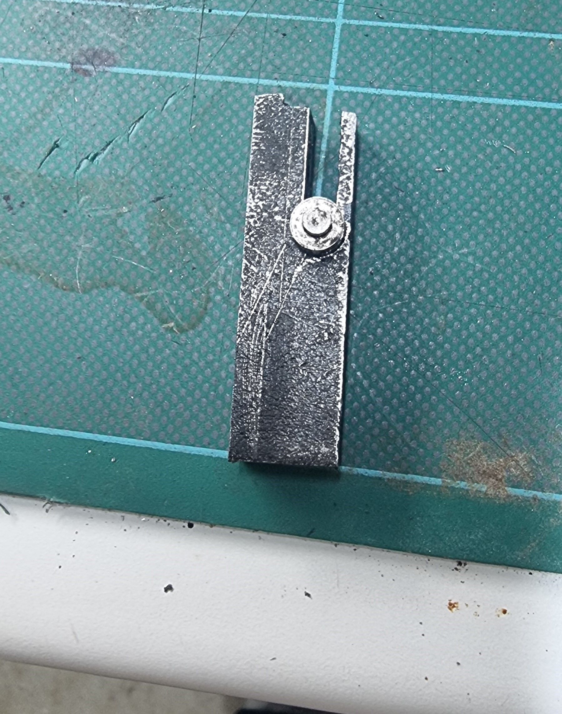
Next was the fork, for this, I used an offcut of black steel, it was the only piece I had in stock that was close to the required size. The fork is 5/16 wide with a 5/32 slot down the middle, after machining the slot I roughly marked out the shape as a visual aid for the next stage. Here you can see the rough blank ready for further machining, a point to make is that the two holes identical to the arm have already been drilled.
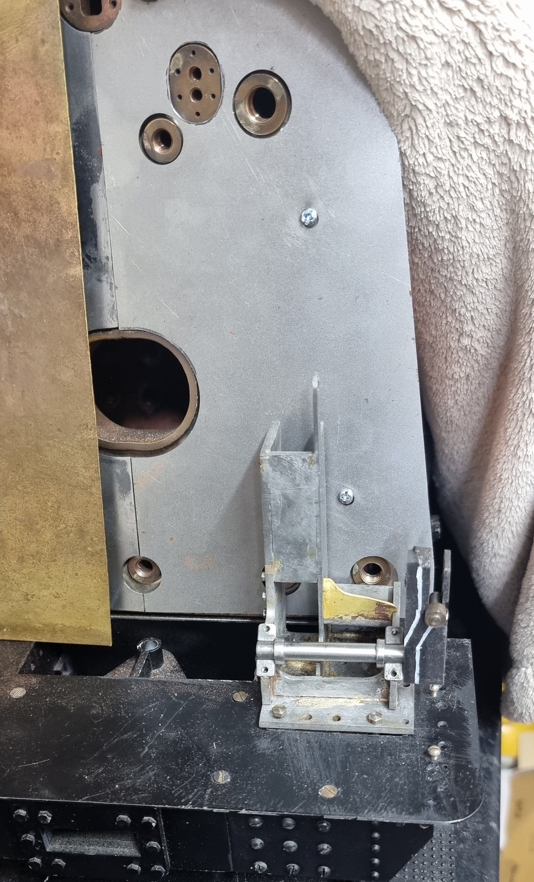
Before making a start on the final shape I checked the shaft along with the fork blank loosely attached for clearance along the firebox, bear in mind that the cleading still needs to be formed around the backhead corner.
I then removed the excess material from the fork, first chain drilled followed by step machining close to the profile.
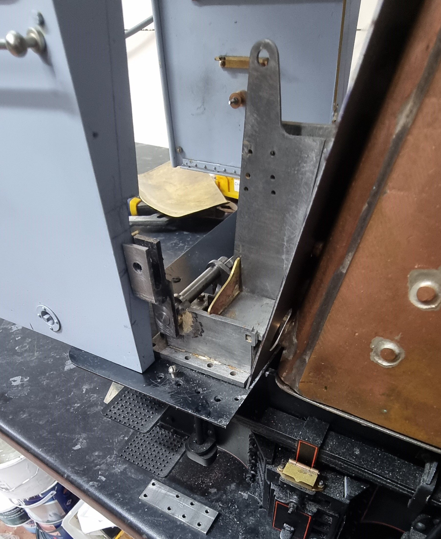
For peace of mind, I dug out the cab from its storage box to get an idea of its position compared to the fork, (not seen that in a while). Note the slot cut into the spectacle plate, I did this when aligning for cutting the slot into the running boards for the reach rod to pass through, I will adjust this if required once I can check against the reach rod itself, The reach rod shape dips down past this area and is hidden behind the firebox cleading.
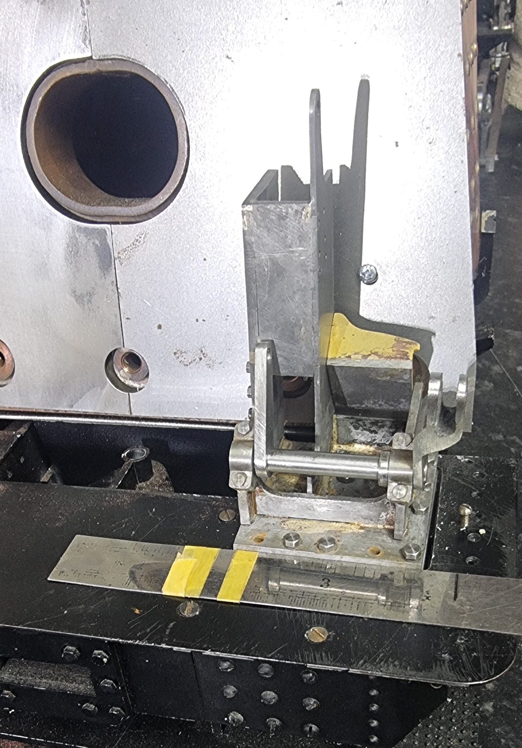
Here we have the completed components (not yet brazed) dry assembled to check fit, Don gives a dimension of 4 1/4 distance from the centre line to the outside edge of the fork, this is shown by the black line marked on the rule. Note in the previous pictures that I hadn't mounted the stand properly, here she sits in the correct position.
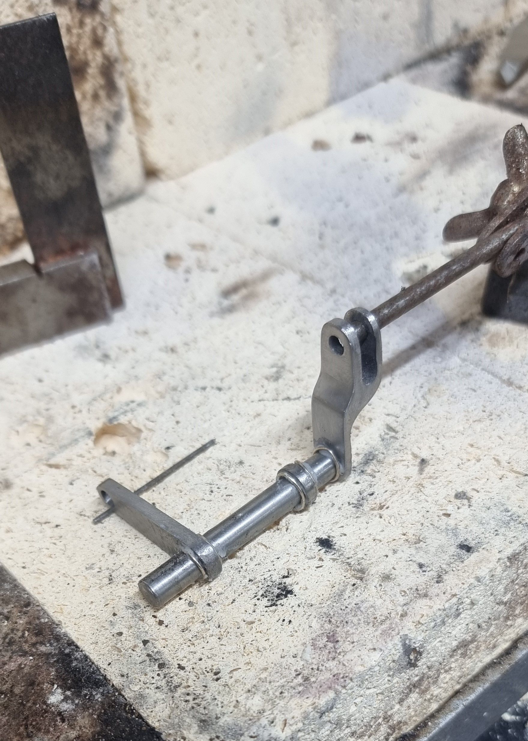
It was then time to silver solder the shaft parts together, here we see the parts with coils of silver solder wrapped around the shaft where required. Parts were thoroughly fluxed before assembly, a small broken number drill was used to get the arm sitting level and a simple jig was made using an old helping hands stand with a length of 5/32 steel rod to hold the fork upright and clock the arm to fork at 90 degrees. ( I noted at this point that pictures of A4's show this arm to be pointing down, not up, I checked back just to be sure that Don didn't have this wrong, I guess there's a good reason for this, perhaps something to do with the streamlining?) Someone will know..:)
The completed shaft
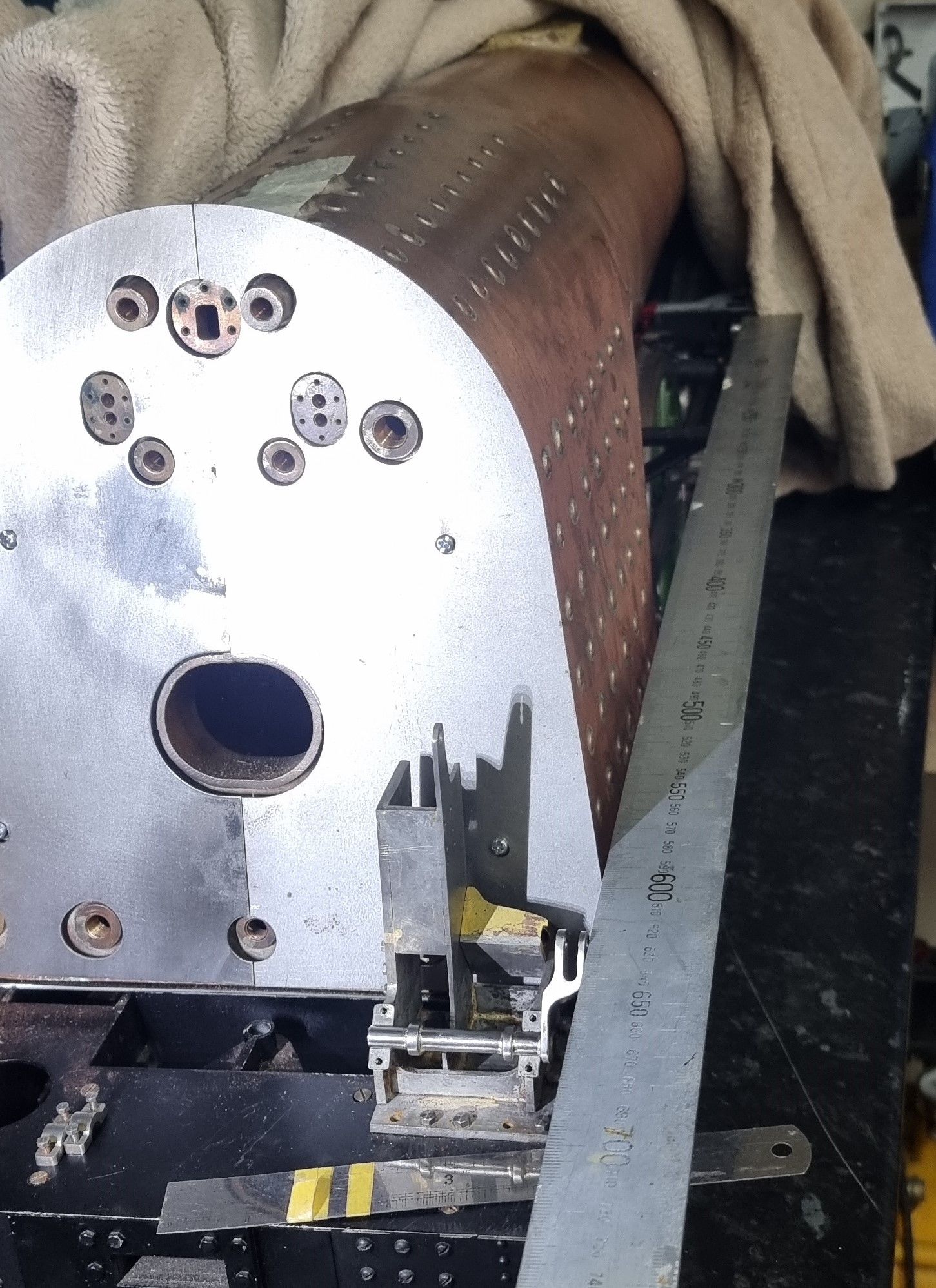
One final check to see if things looked right was to sit the shaft on the lower bearing blocks and hold a rule alongside the shaft and the lifting arms up forward, all looked good with the rule crossing the main running board bracket just where there will be another smaller bracket which the reach rod has to pass through.
Some last details to the stand before painting were to drill/tap some 10BA holes for the sanding valve and an oil box to bolt to. The oilbox feeds the shaft bearing blocks below. These positions were taken from photos although are reversed as the photos used were for an A4 and thus LHD. There is no drawing for the sanding valve but according to Don a 3/32 globe valve can be adapted for the task, that's for another day.
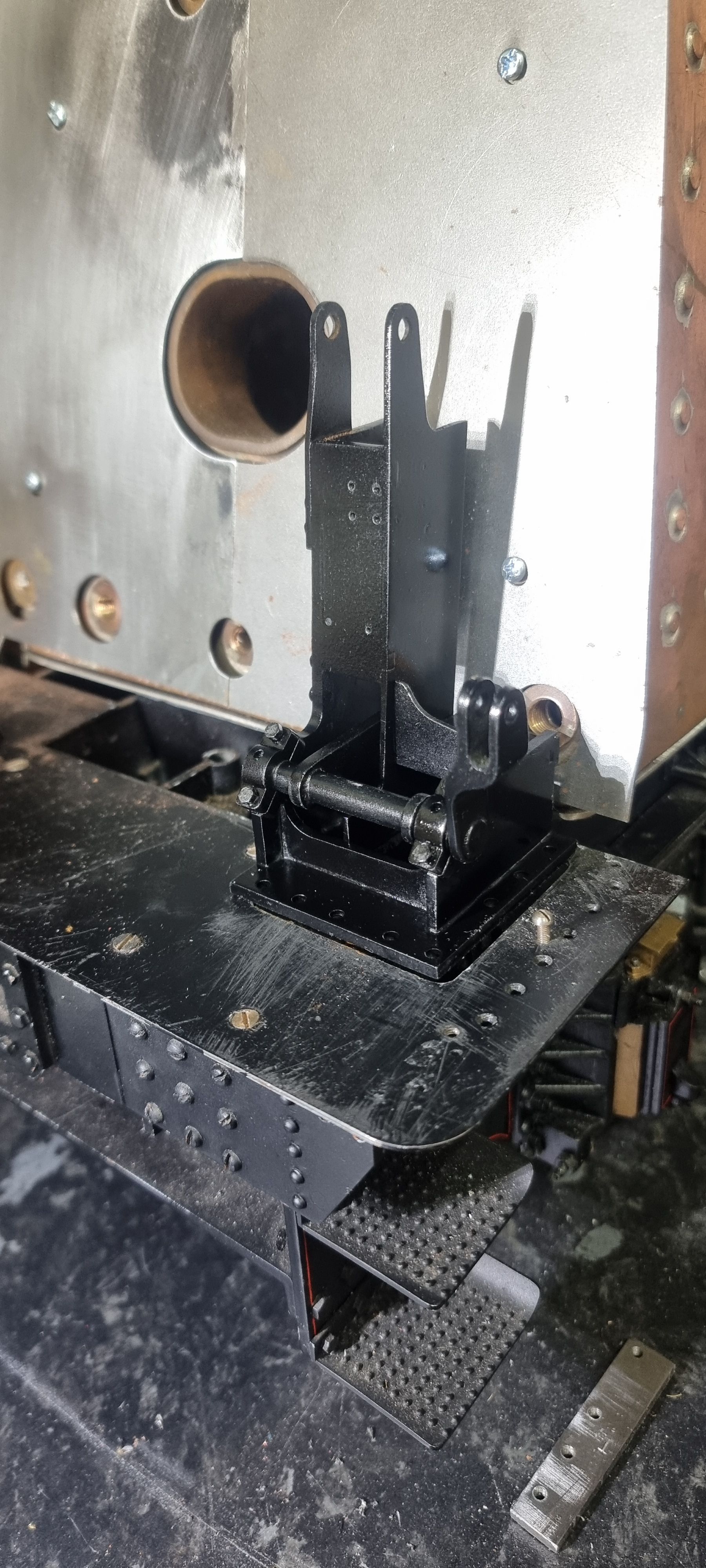
stand and shaft are now assembled, but the paint needs the final prep/coat, it looks like most other parts in this area also need some dusting and fresh paint..:)

