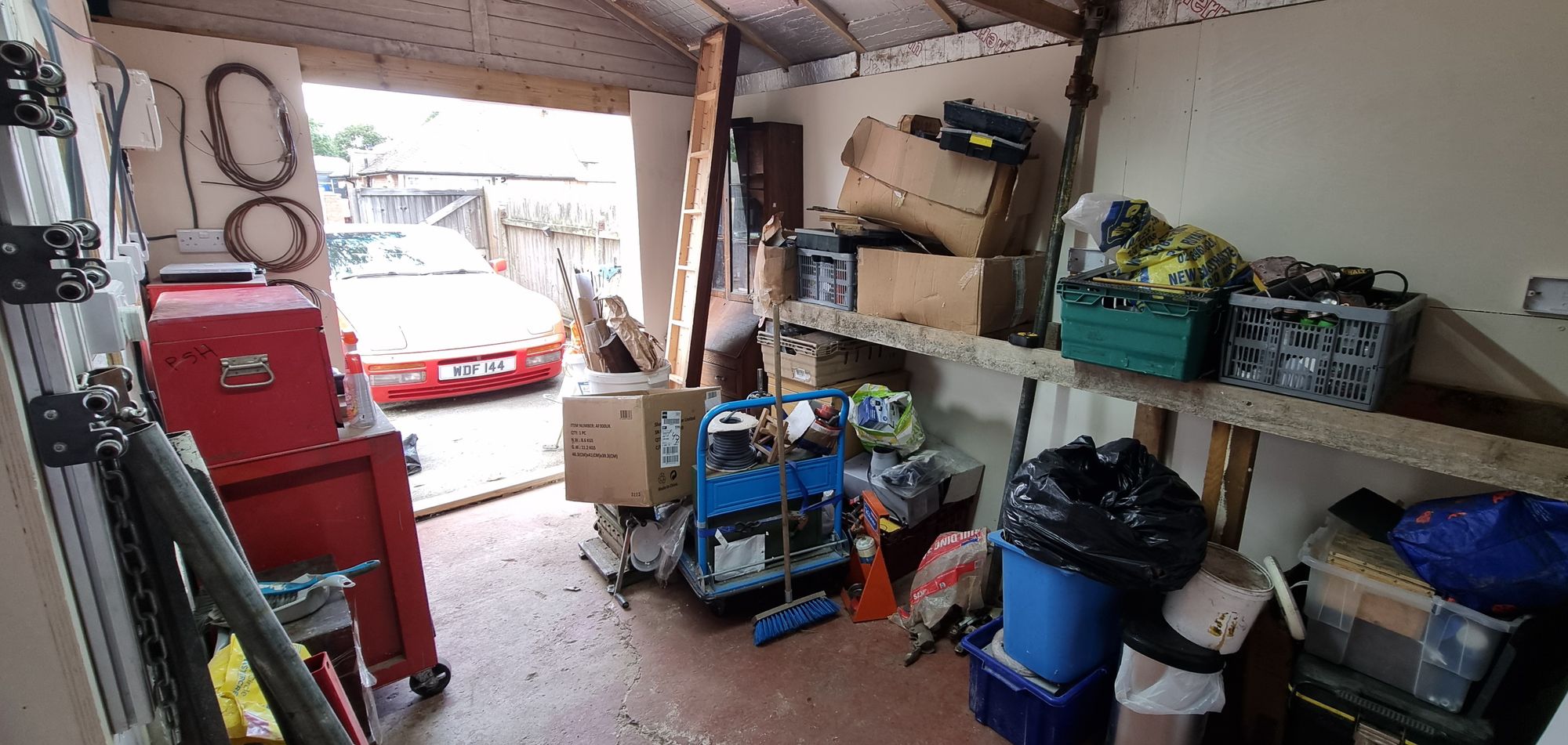
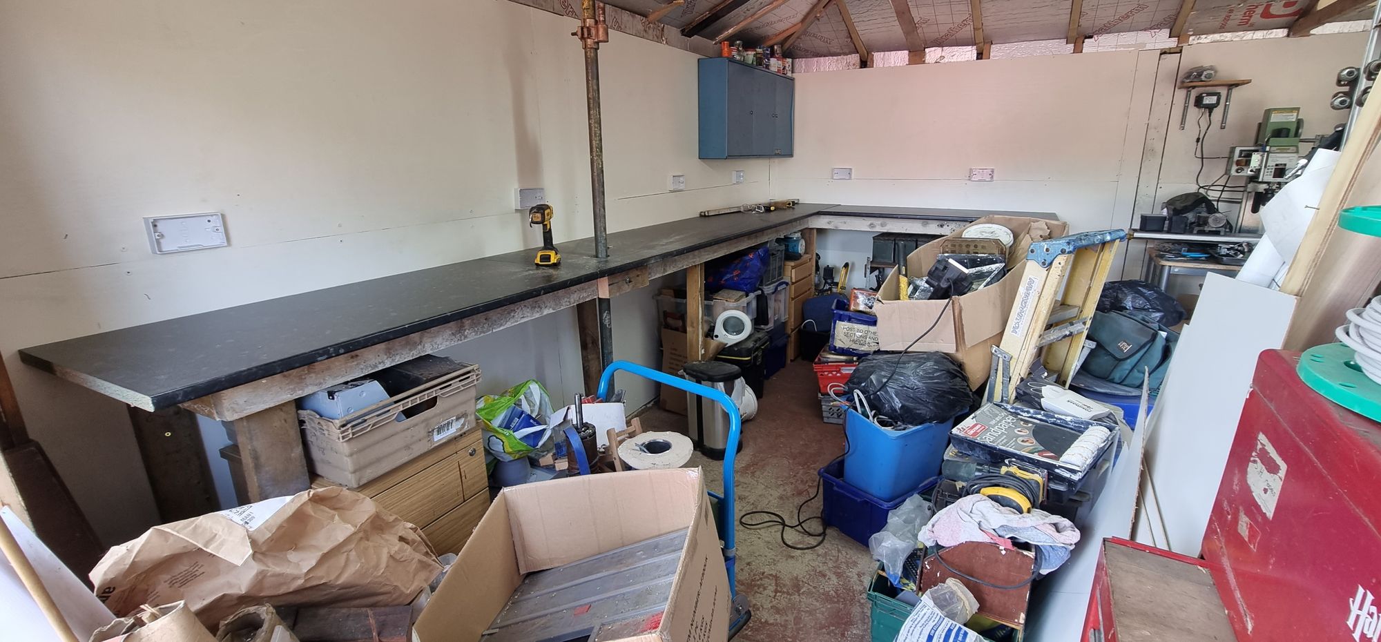
Having already built the smaller workbenches in the new building and now that the main area was covered in Plywood I could move on to building the larger benches which will be where most of the work on the loco will take place. The other benches will be used for smaller scale models ( I have a G1 King kit to build) and also doing some of the finer detail parts such as the backhead fittings when I get to them.
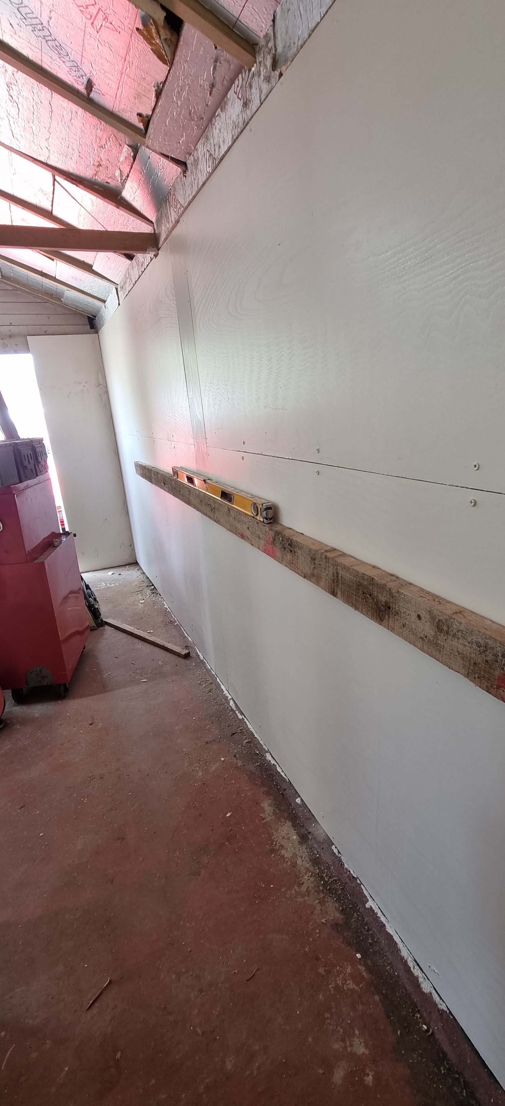
This main bench will also take the shape of an L, one side being 2.1 mtrs along the back wall and the other along the side wall of 4.2 mtrs, this is where 4472 will live for all of the remaining work to be done until completed. We begin with the first picture showing the support beam screwed into the plywood along the long wall. This will have legs added to give the needed support for the weight of the loco, currently, it stands at 244 lb but this figure still has a way to go. The space left at the far end is for my old book cabinet to fit into.
I then built up parts of the frame for the bench, note that for the beam along the wall, I cut the legs to sit under the beam and then screwed them to the wall. This is so that the weight isn't all sitting on the screws in the ply, the outer legs are cut to the same height as the frame and screwed to it, I can do this as the weight is still supported by the 4 x 2 legs and not the screws that secure them to the frame, hope that makes sense.
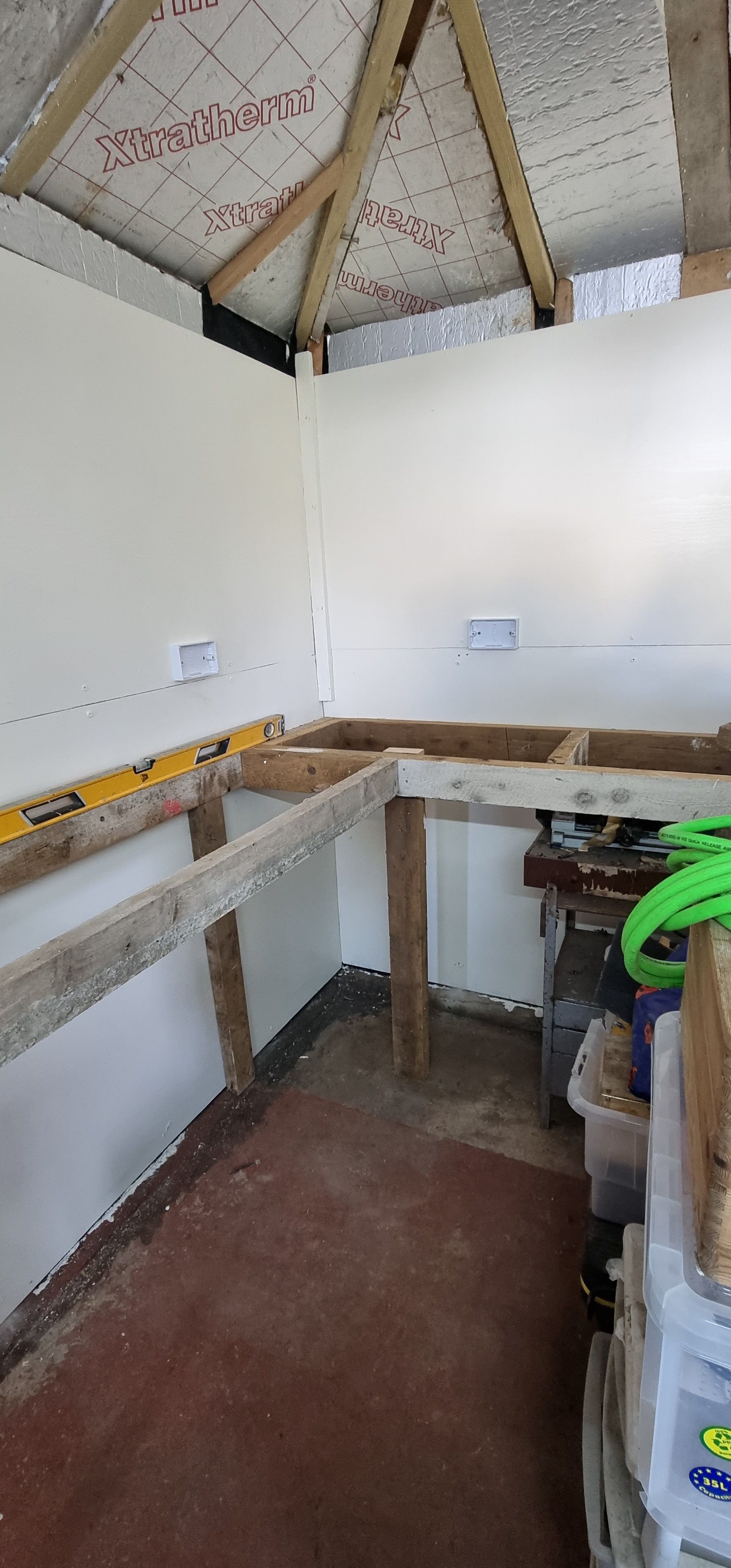
With the frame erected, I could temporarily store some gear off the floor while waiting for the worktops to arrive. I chose 2 x 3mtr length 28mm laminated kitchen tops from Travis Perkins. I chose this size as I wouldn't be able to fit the hoist support if fitting one long 4.2m top, it was a struggle with the 3 m. Note the scaff tube leaning approximately in its position awaiting the arrival of the work surface.
A picture tells a thousand words, or so they say. The worktops have arrived and are resting in their positions ready to be screwed to their respective frames. It all looks so easy but trust me even with cutting a larger hole for the tube to pass through it still took two of us to manhandle everything into place, lucky for me my new neighbours are very helpful.
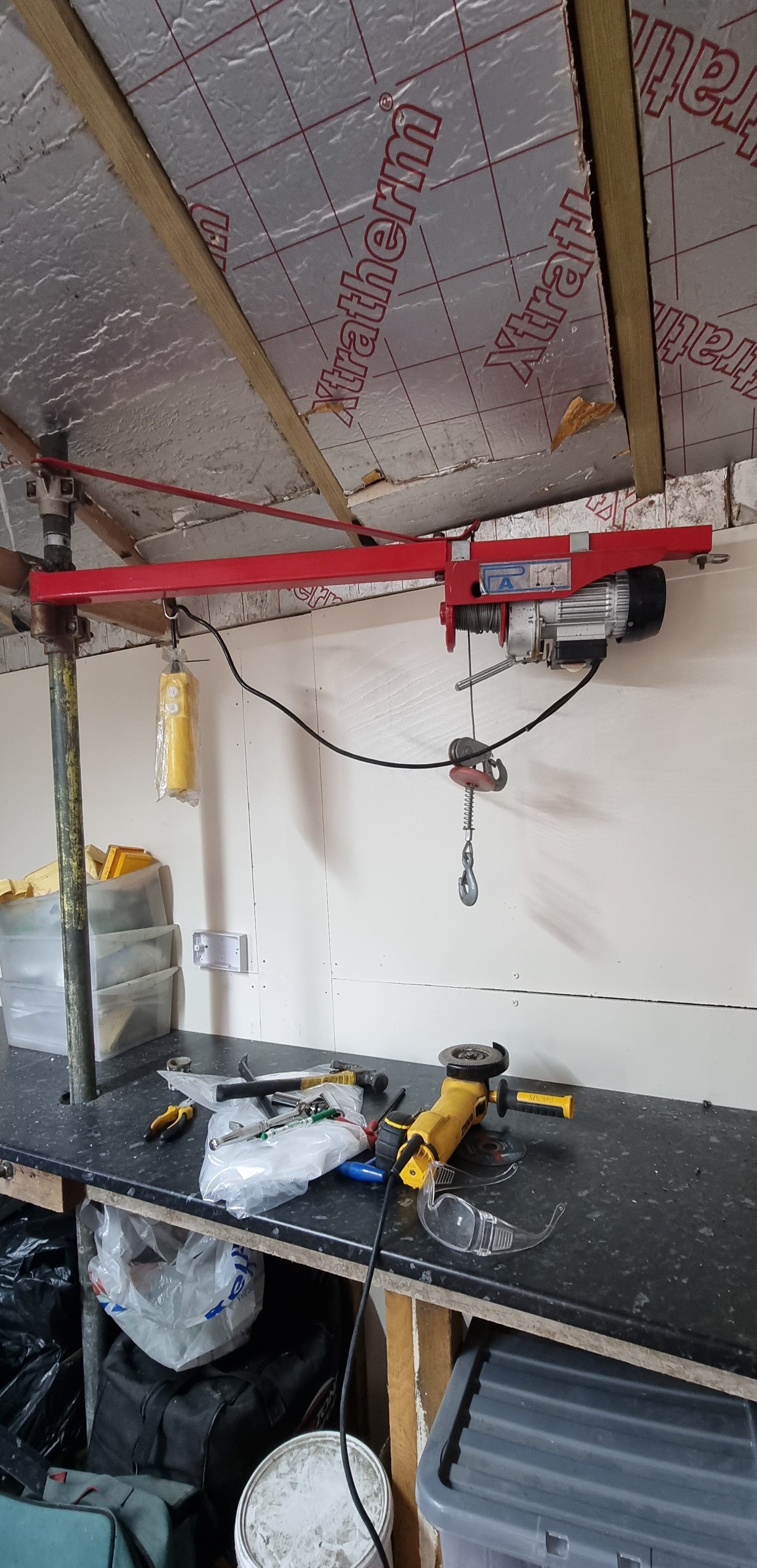
On to the hoist, when selecting a position for the hoist I needed to consider the area around it so that I had room to lift the loco to both work on and also to lower to the floor and where it could be supported at 3 points. As it happened the supporting trust which was placed to allow an 8-foot roofing board to reach was ideal for what I needed.
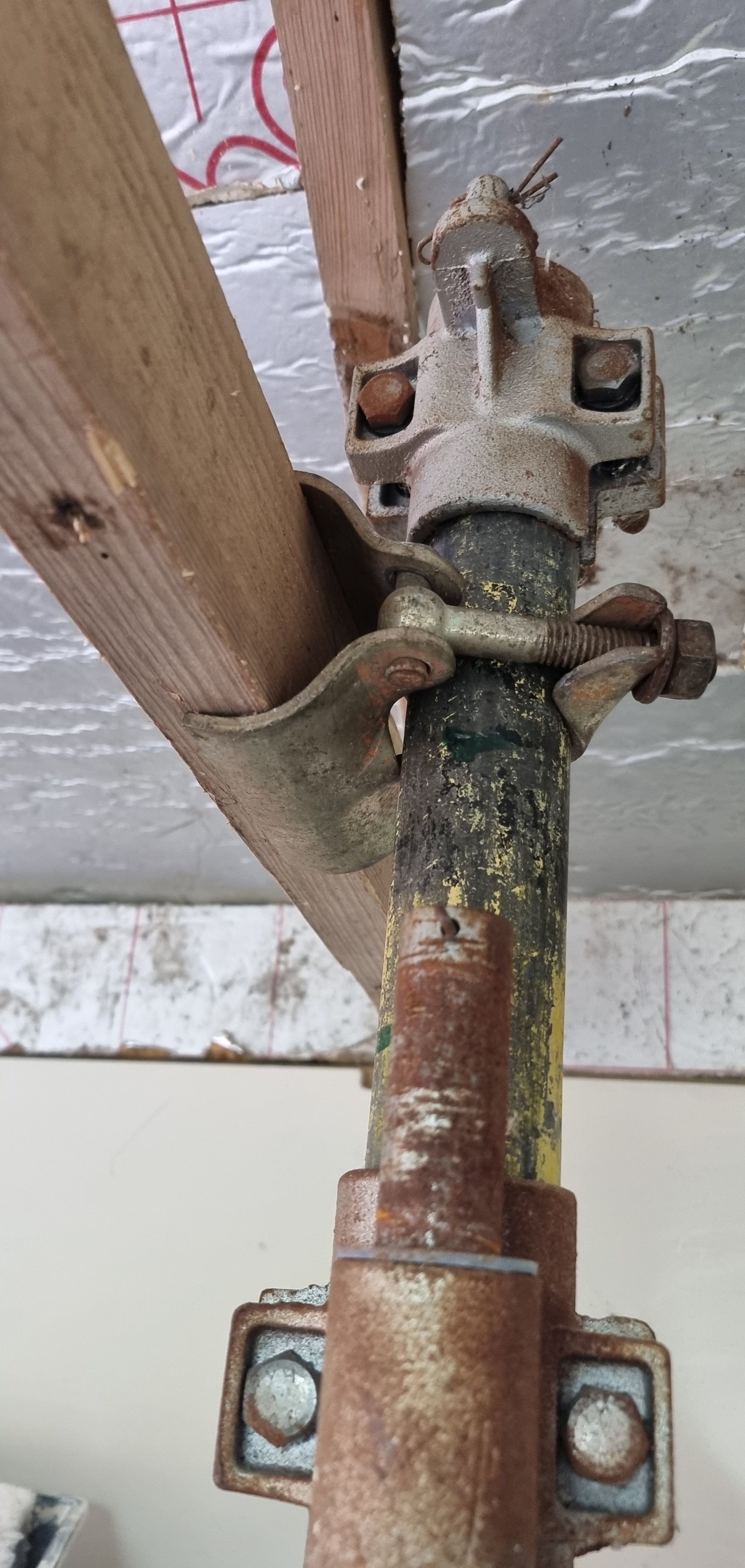
This is an early picture showing the minge clips (yes that's the correct wording) clamped to the wooden trust crossbeam. There is an extention peice sitting on top, this was for the height of the old workshop, I have a little more height here and thus later cut a longer section of tube to fit. The two castings are to support the swinging gib, more on this soon.
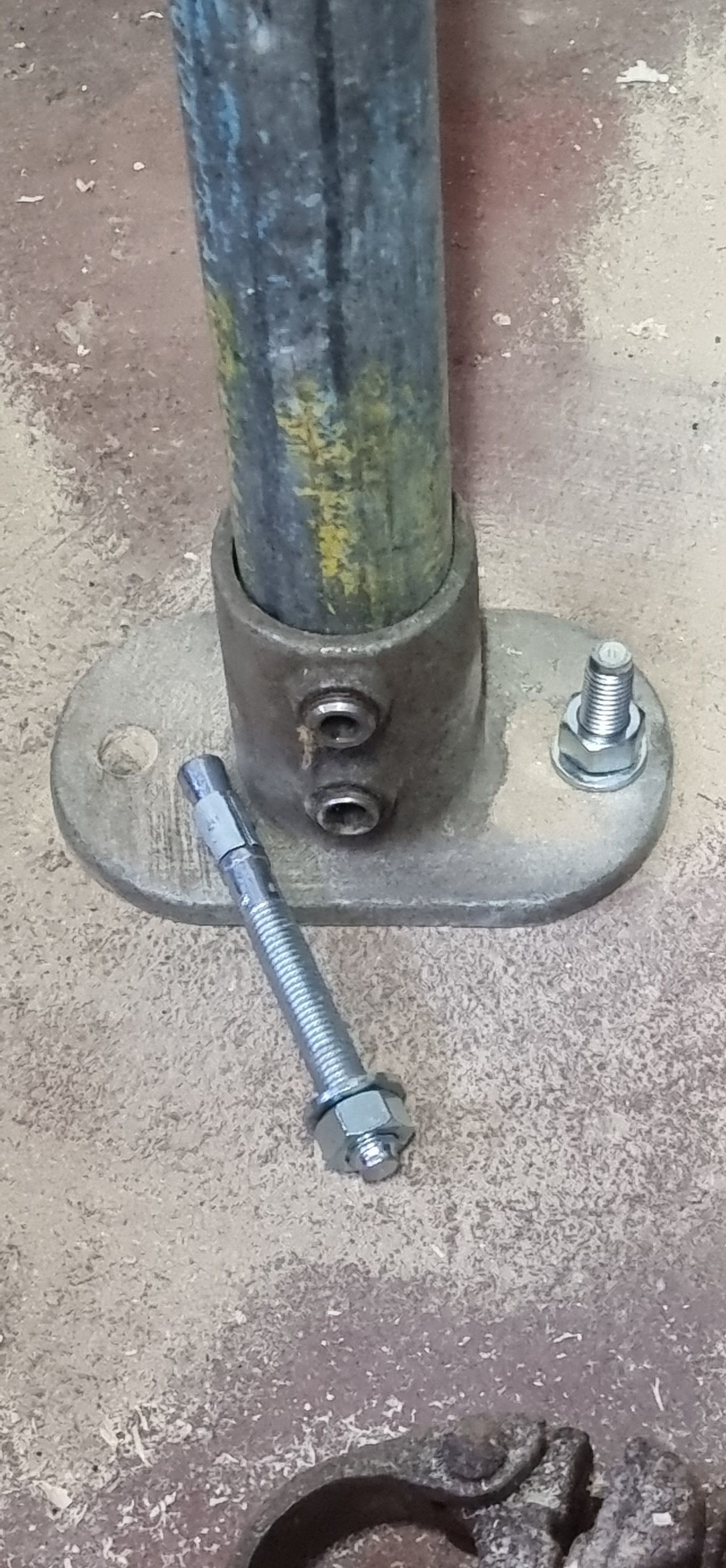
At the floor I have used a floor mount which is held to the concrete floor via two anchor bolts, think they are 10mm. As can be seen, one has already been fitted with the other awaiting tapping home into the drilled hole before tightening up. There are two grub screws to hold the tube securely to the mount.
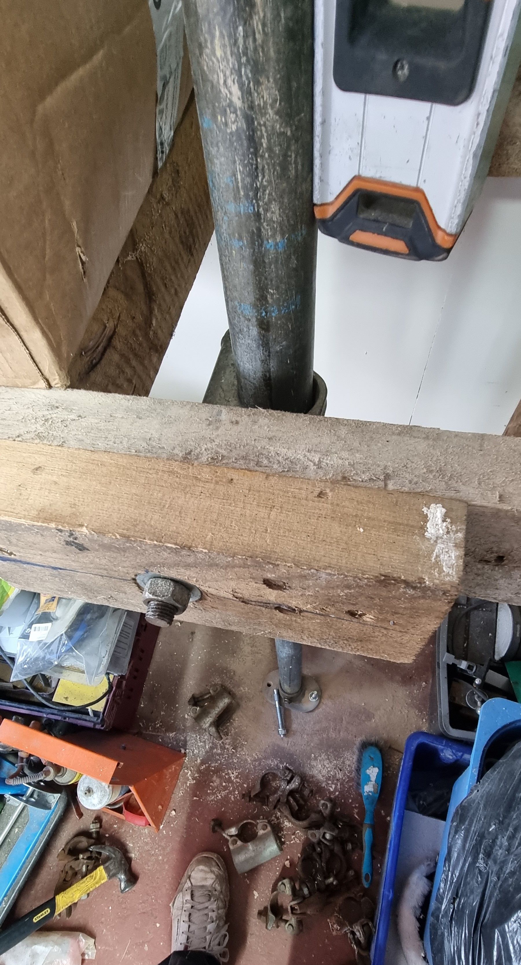
that's two of the securing points taken care of, the 3rd is into the bench frame itself, here I have doubled up on the frame timber to give plenty of meat for the special mounting clamp used. Once all mounting points were attached, the tube was checked for being upright and then everything was tightened up fully.
A final picture of the hoist gear, the hoist itself was bought off eBay, and there are a number of suppliers to choose from, the same goes for the swinging jib. This setup has proven itself to be very strong while in use at the old place, this should be stronger still as it's bolted to a concrete floor whereas before it sat on a wooden floor. The electric hoist is rated for 250kg, you can buy bigger but this suits me for the task at hand.