
The beading is an interesting subject, I have seen a number of ways of doing this from others. In this case I have used some of those ideas and also my own but at the end of the day, there's many ways to skin a cat.
I did ask myself that perhaps I should have chosen the 'streamlined' tender with which has no 'beading'? Only kidding, it's a fair bit of work but makes all the difference to the look of the tender.
The method that I have used, that is in drilling/screwing the beading to the panel to hold it in place for soldering, I have since seen used on the new build of the Gresley P2, although in this case, of course, the beading was welded.
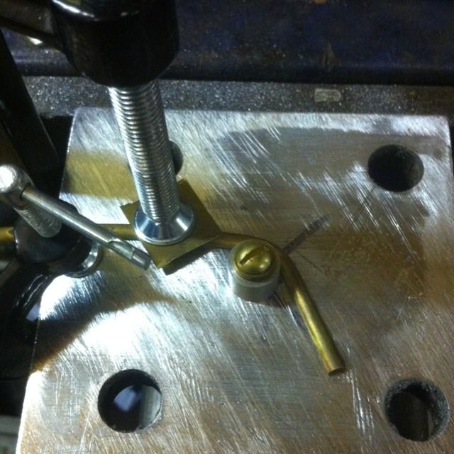
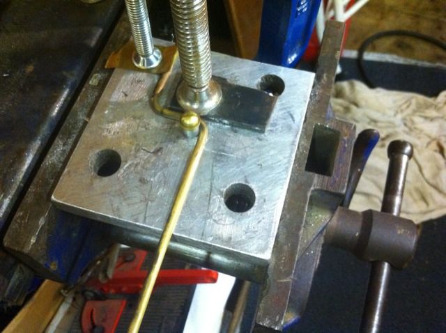
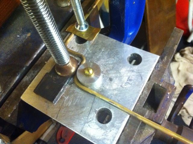
The piece in the picture is the beading for the front panel having been annealed prior to bending. Here you see it in a jig , idea borrowed from another Model Engineer. I used a scrap piece if alloy, I then turned up a piece of alloy to the correct diameter , drilled for clearance to accept a 2BA bolt , the plate having already been drilled and tapped to accept it.
A paper template was taken from the tender rear panel (same as front but easier to draw around) and the pattern was drawn on the alloy plate for both the left and right hand sides. The beading was then bent to shape and held by a clamp with a positioning mark lined up with the turned collar for the next tighter curve. The beading was then gently tapped using a hammer and piece of wood until it matched the drawn profile.
The important part here is to ensure that the beading remains flat, ie, no twist, it's actually much easier than it looks.
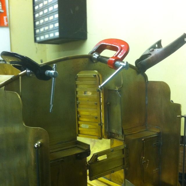
The beading having now been shaped for the left hand side, was held in place via clamps, holes were drilled into the beading which were then tapped for small brass small screws. That was the original plan but I ended up just using the clamps for this section. The sides though were held as planned.
Having completed the shaping of the left hand side I then marked the right while the beading was held in place and then put the beading back into the jig but this time using the right hand profile for shaping.
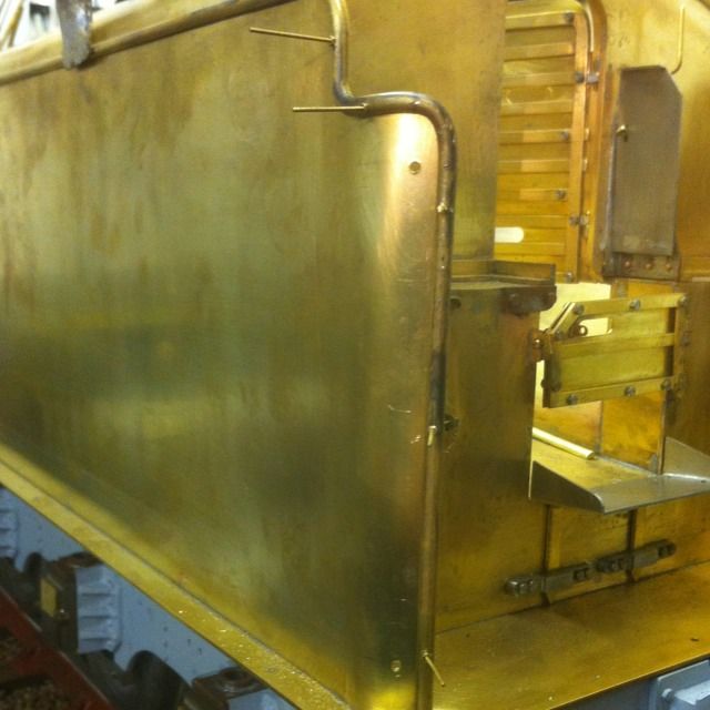
Here we see the beading now shaped and soldered to the front panel, one part down, plenty more to go.
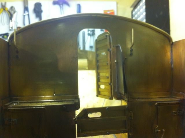
Next up was the rear of the coal bunker panel, similar to the front and followed by the rear panel itself, both now have the beading soldered in place.
I then tackled the two internal strips, here we see the left hand side. This took a little more thought as it not only curves around the side profile but also follows the curve inwards. IIRC, my procedure here was to do the top two curves first, form the inward curve and then the final curve downwards, last job was to cut the beading to length.
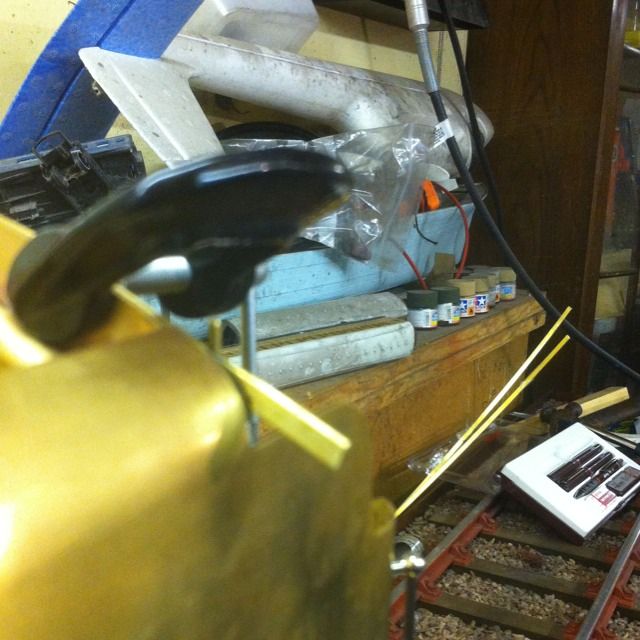
It was then time to tackle the long pieces of side beading , this started with the front curves for which I needed to turn up another collar for the tighter curve involved too.
The first two curves for the side beading were formed using suitable rad collars and then switched to a larger collar to form the larger curve which takes the beading down the length of the tender (see next picture for details)The beading was left overlength and trimmed once fitted to the side sheet and blended to match the rear panel beading. Only the curved areas were annealed for this piece, it's a very long tender and you need to get this piece as straight as possible.
With the front of the side beading shaped it was clamped at the front edge of the side sheet, having already been drilled to accept 14BA brass screws. While held in place the first three holes were drilled so the front edge could be held tightly so that I could calculate/form the final top bend around the side sheet's front curve( the length of this piece was calculated before hand)it was then a simple task to drill the remaining holes around the other curves and down the side. This piece was then removed and the internal piece was held in place via clamps so that it's holes could also be drilled , once this was done both pieces were positioned and held tight via the 14BA bolts which now go through both the tender side and the two pieces of beading. It was then a simply task of sweating in place.
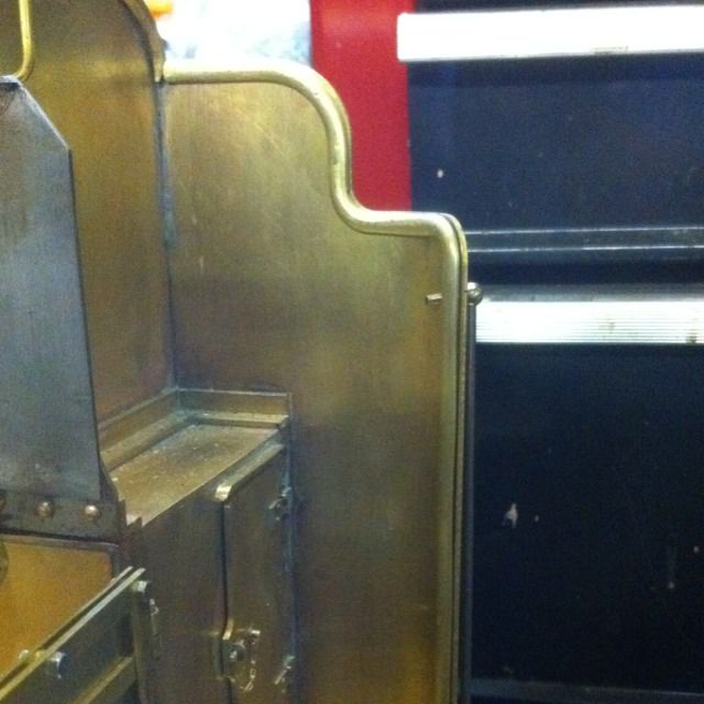
The completed right-hand side, once sweated in place the screws were cut and if required a little more solder was applied around them to fill any indentation.
Well according to the drawings that was it for the body, I had a few more bits I want'd to do though , the upper door clasp which I now had a better understanding of how it operated was one of them.
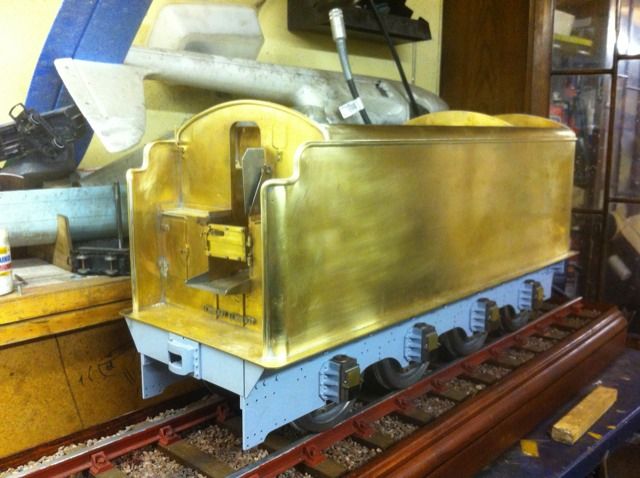
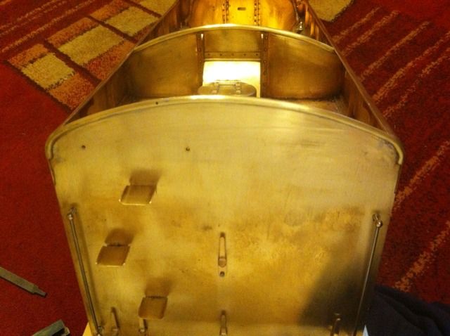
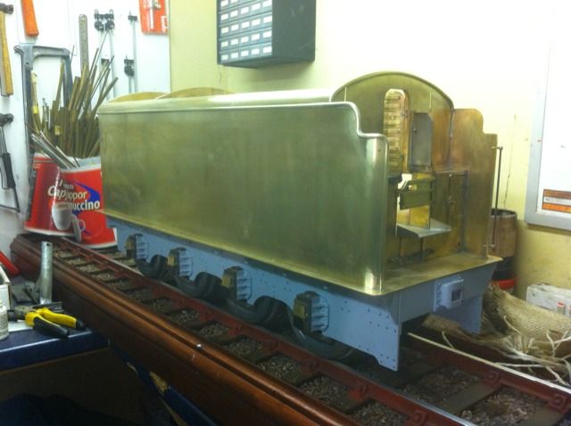
Here we have the tender with it's beading permanently fitted.
