Last time we built the the front section of the reach rod, this time we shall tackle the rear section and the two pins required for fitting of said reach rod. There's no 'fork' to worry about this time and one might think that this would mean a speedy construction for the rear but we do have the the 'I' beam type joint to construct which actually is more work than a simple fork.
Having said that I did set things up in the last issue which saves us some time, that being deciding on a tongue width that matches one of the cutters I have to hand thus making life a little easier. After setting up the rear blank in the machine vice and clocking the centre I set about machining the slot on both sides to create the 'I' beam required for the front section tongue to engage with. I marked out the length of the tongue and machined to the line. The first picture tests the tightness of the fit between the 'I' beam and the tongue. Of course, I can't fully engage the tongue here until I cut the corners.
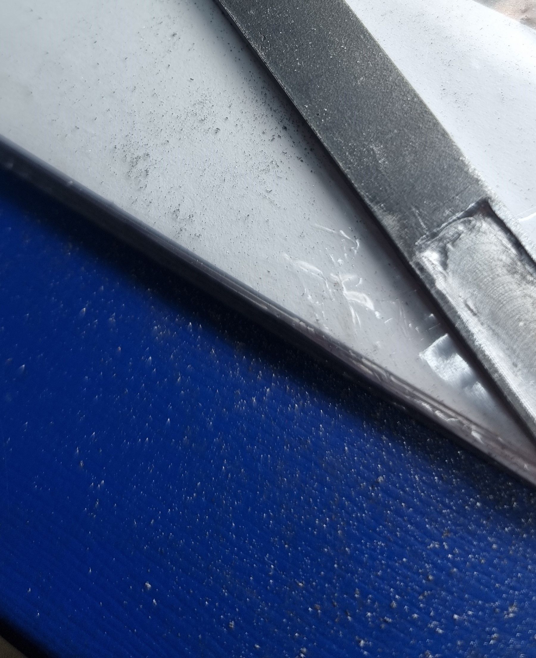
I then needed to cut out the corners, I did this first with a suitable chisel followed up with the Dremel and a small cutter.
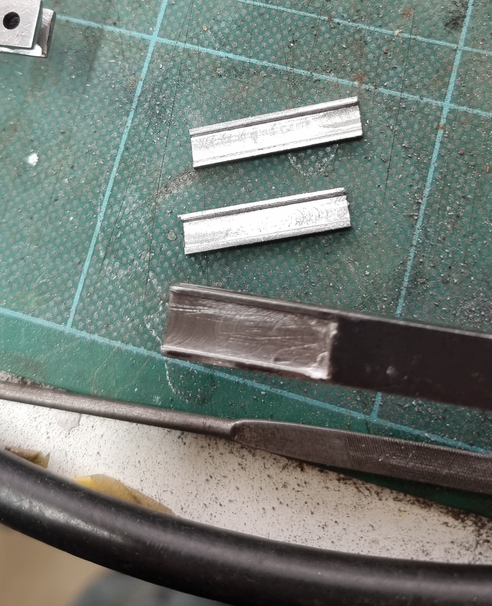
Next up were the bulges seen top and bottom around the joint as shown in my photo of the prototype's reach rod last session. I approached this by creating a channel in a piece of steel bar that I first machined down to a size required to match the full-size scale and then cut in two to give both top and bottom sections. The channel was cut to a depth that when fitted would also engage with the tongue, the width of the channel matched that of the reach rod itself. here we see the two sections ready for brazing to the rod, once fitted they were then machined to length.
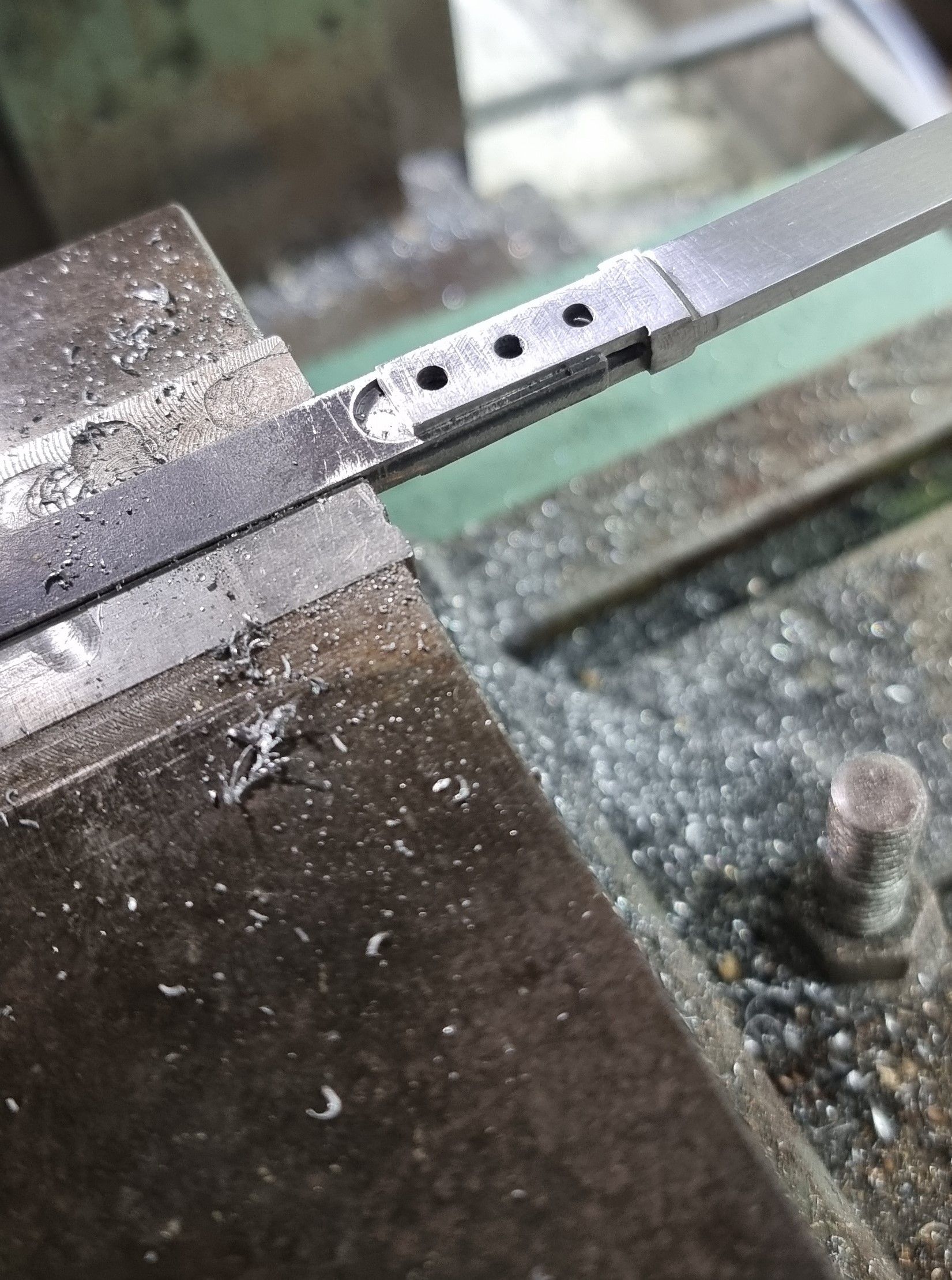
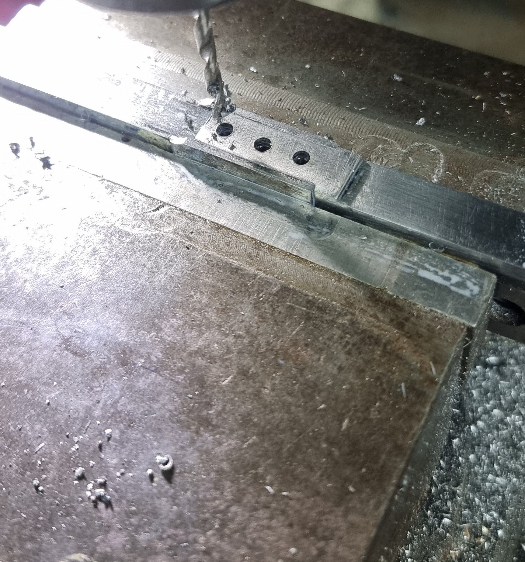
Once the bulge sections had been fitted I could shape them and push the two rod sections together and drill through the 3 holes. These parts are a drift fit and care was taken not to mark them using a wooden drift and small hammer to tap them home. Here we see the holes being drilled, before doing this I shaped a length of brass so that the bulge was encapsulated in a concave section of the brass bar chosen. My thinking here was that I didn't want to risk a void below the part when drilling in case the drill wandered off and pushed the other tongue down thus ruining the hole on the other side. The brass support was shaped so that with the bulge sitting in the concave in the middle, the sections of the reach rod themselves were laying flat along the top of the brass support keeping everything square, hope that makes sense? Note that I have already done some of the profiling to the bulge, ie the concave recess seen on the left-hand side. On the right-hand side, I have made the tongue thickener part a little longer than the prototype, you'll see what I mean if you compare the two. I did this to give more strength to a part already made up of several parts. If I had made this all out of solid as I mentioned last time I could have reduced the length of the thicker part of the tongue to match the prototype, hey ho....:)
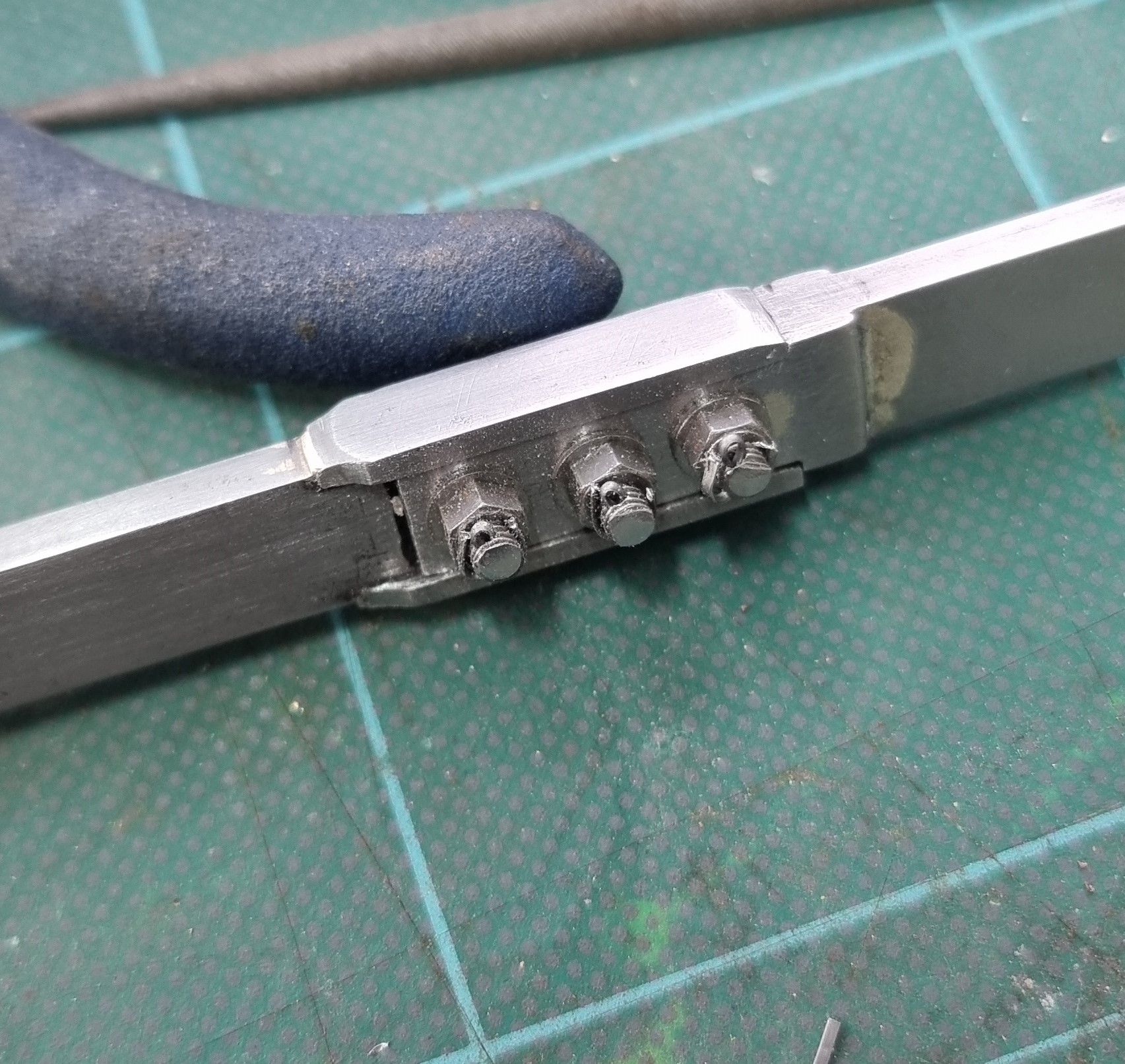
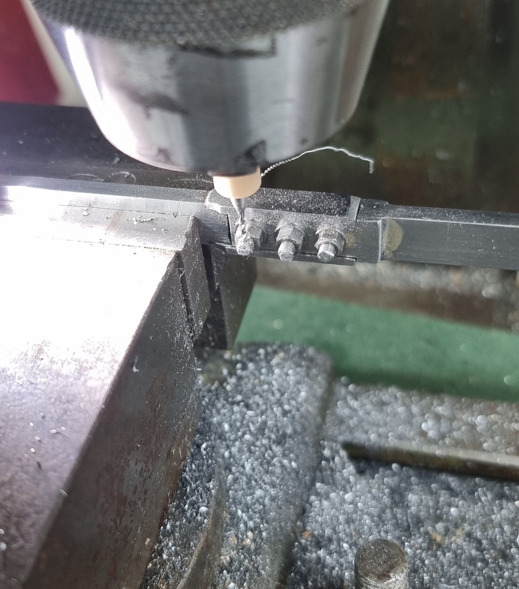
Here we see the general shape of the joint very close to its final stage, just needing a final polish. The 6BA bolts have been fitted with washers on both sides and then cross-drilled to accept 1/32 split pins. I reshaped the pin heads to make them closer to scale size, a simple job for long-nose pliers. I used a suitably sized PCB high-speed drill at more than 1000rpm to ensure a hole that stayed on track and not deviate from the planned route close to the 6BA nuts.
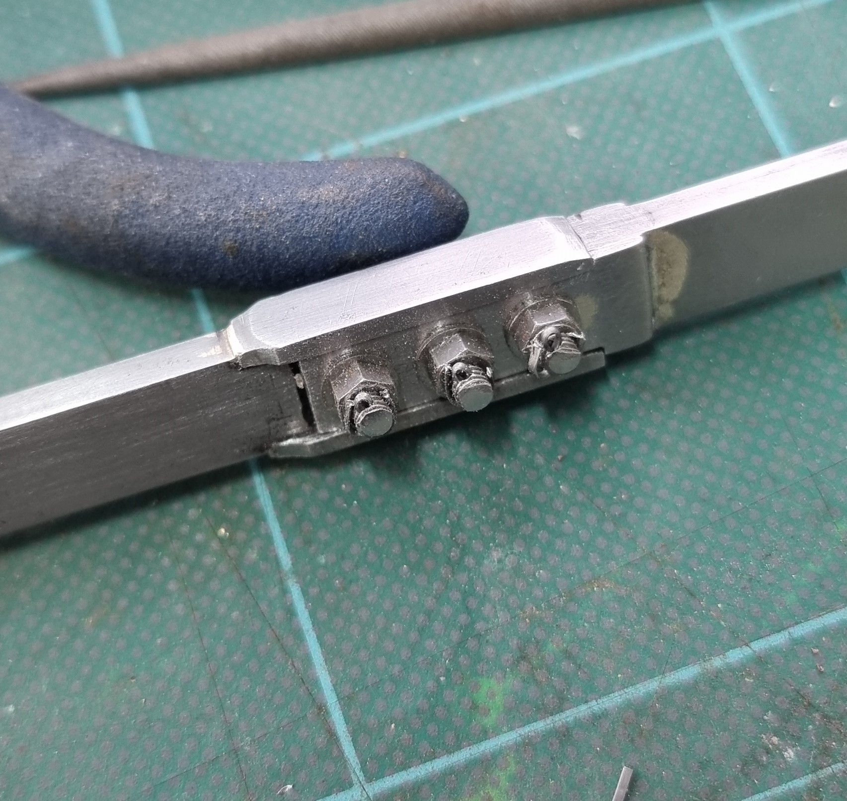
We have a finished reach rod (well except for the final polish), a close-up of the joint tackled this session.
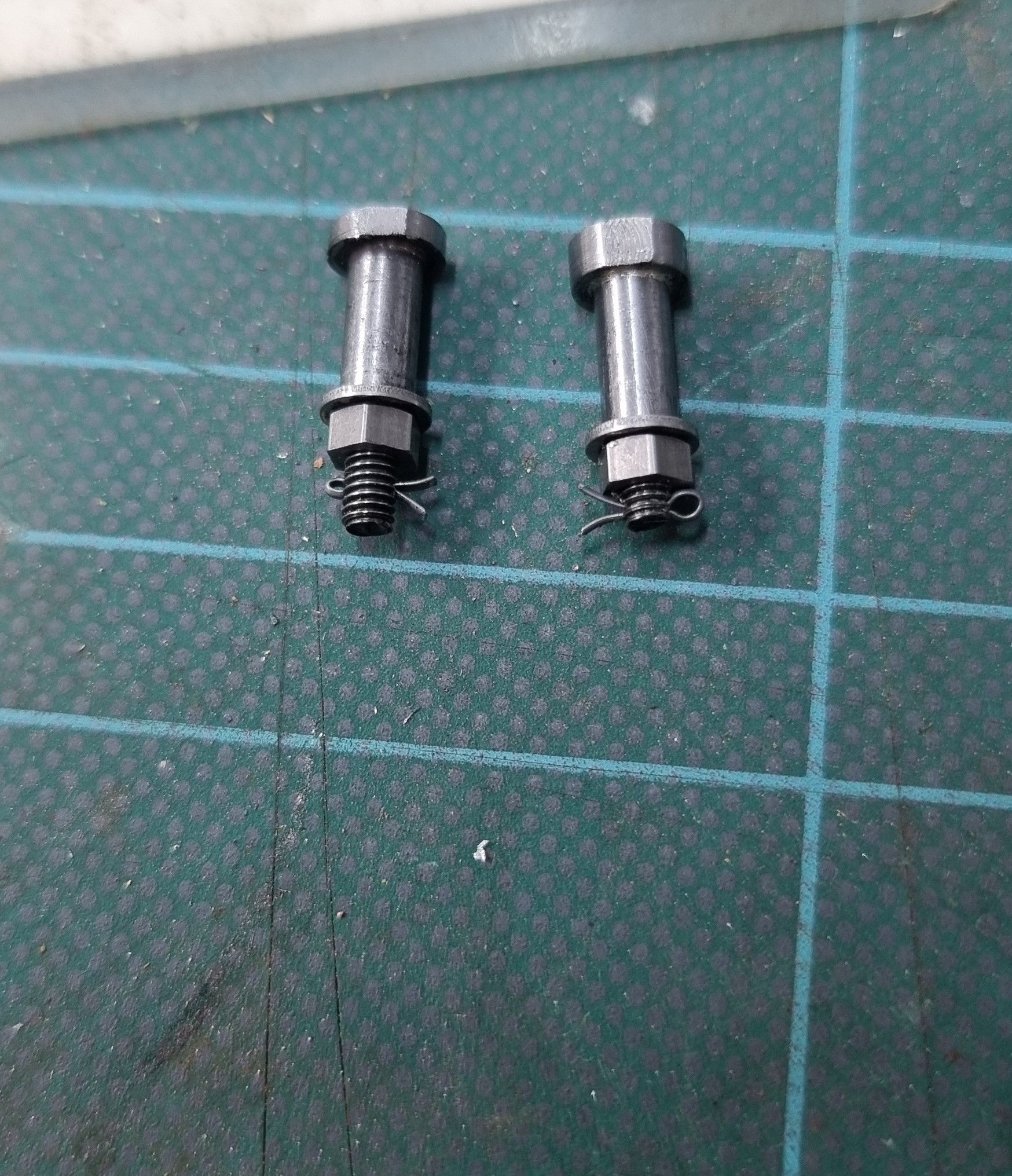
The only thing left was the two pins required to fit the reach rod, the two are very close in size ( made so that when tightened fully there is a slight end float to allow free movement on the reach rod ends) one has a thinner head as there's not much room in the cab between reverser shaft and cab side sheet. Both pins have had flat spots machined allowing for a 5BA spanner to make a good purchase for when tightening. These were built using the same method described for other pins throughout the build.
One question to answer is whether 4472 had a painted reach rod as she does today, back in the late 1930s. She certainly didn't in 1934 when she did her 100mph run as we have the famous photo showing the record-breaking crew standing in front of the unpainted reach rod. I'll see if I can find more pictures closer to 1938 to confirm my belief that the rod remained unpainted for my era.

