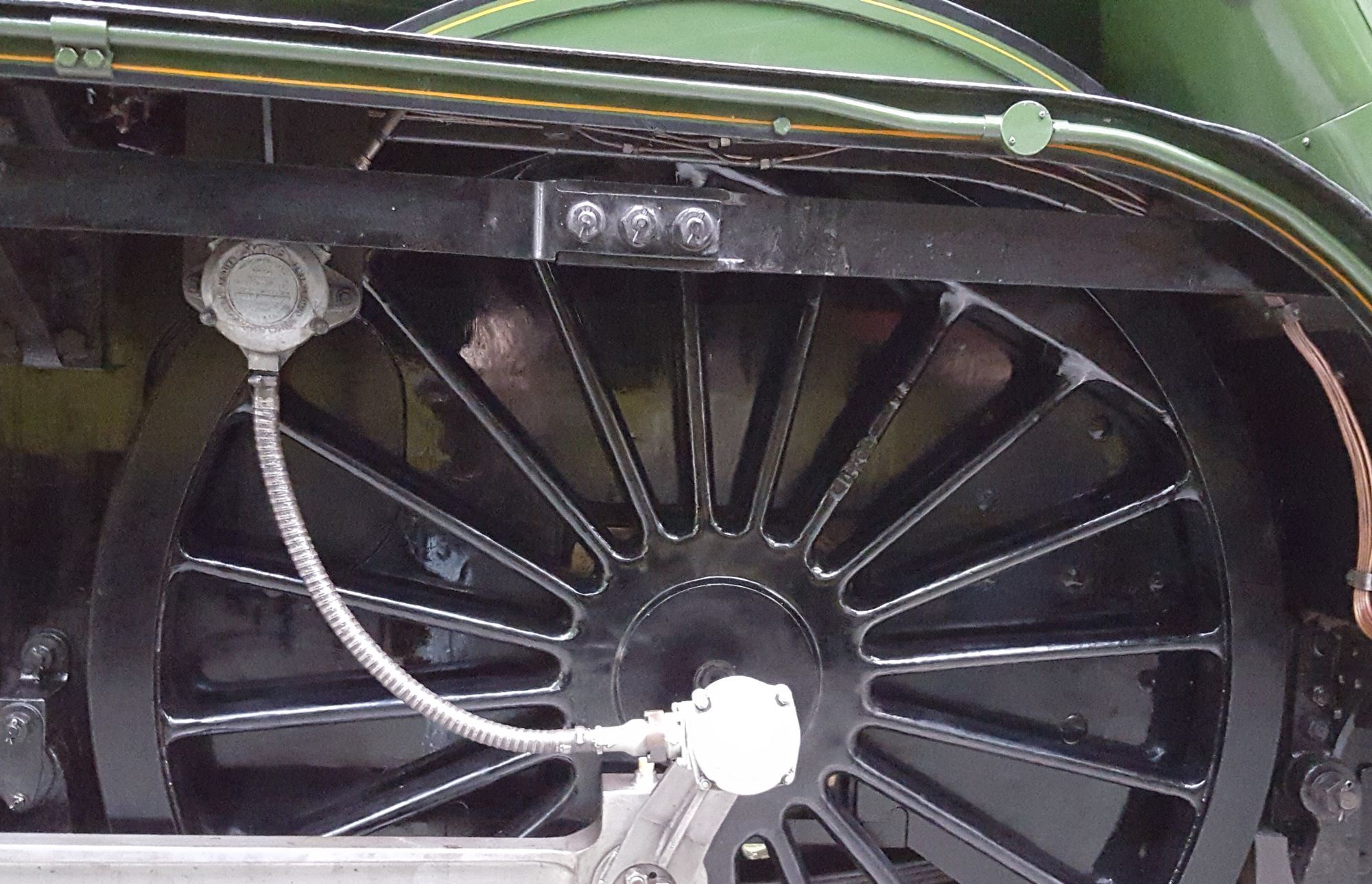
Last time I said that I needed to look into the reach rod joint as Don's drawing wasn't very clear and as it turned out, not to the works drawing although in his defence it would look like it was from the side which is mostly what one sees.
Over the years I have been fortunate enough to have some invaluable help from those who follow my adventure, this time I have to thank Colin Green (Riley & Son's) and Rob Walker who is currently researching FS to build his own model in 7 1/4, I do not doubt that this model will be superb and accurate as it's all being converted to CAD from works drawings and direct measurements of the old lady herself. The trump card was that Rob had in his collection the reverser works drawing which included the reach rod, perfect!
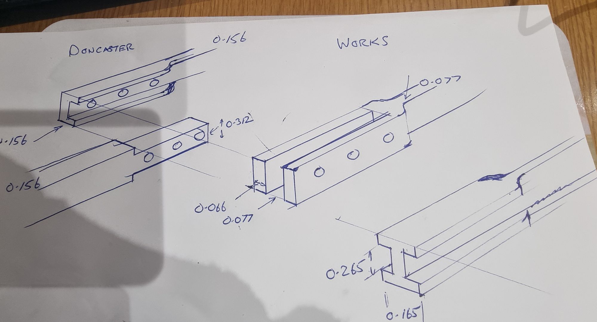
So, what are the differences between Doncaster to the work's drawing...well for one Don has specified 5/32 thick rod (0.156) whereas the scaled-down size from work's drawing is 0.077. That's fine and I shall keep what in effect is a double-thickness rod, the rod is 2 feet long so I can see why Don has gone for thicker than scale, mind you it may be fun getting it to fit inside the cleading alongside the firebox. To help show what I'm up to I have drawn my version of a fag packet sketch on some A4 paper, better than a thousand words but very crude, it was enough for me.
The sketch below shows both Doncaster and works drawings, it's very simplified as it's just for me in the workshop and doesn't include the slight bulge on top and bottom seen at the joint itself but is good enough to show the differences for you and good enough for me to build from. Note that both pieces are shown end on for the works sketch to make it clearer. Don's version is clever, and simpler to make while still retaining most strength in the tongue and not just relying on the 3 bolts to take the push/pull strain. I have included some of the dimensions. The note is not drawn to scale.
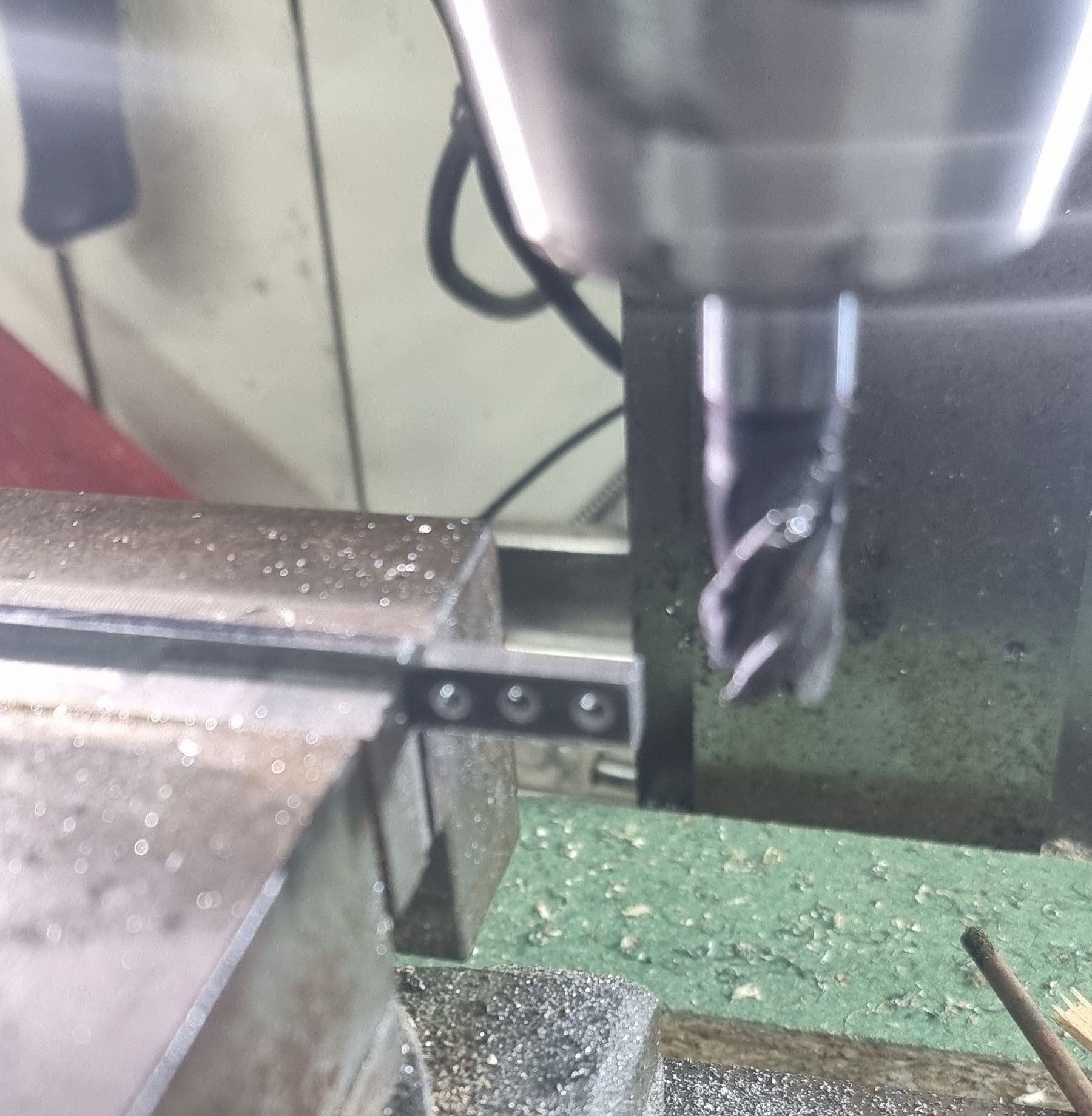
Following Don's overall dimensions I cut the front section to length, (both sections had been laser cut overlength at my request) I'll make the front to drawing and check the rear length in place, I need to be on the ball here as there is no adjustment in the design. The first job was to drill the 3 holes, center's from the end are 5/32+ 9/32+ 9/32 and then machine the step down for the tongue, so far following Don's drawing. For the tongue width I chose a size in between Don's and the works drawing, to make life easier I chose a width to match a suitable cutter to hand making the required slot to the rear section easier.
I then began to mostly follow the work's drawing while using Don's overall dimensions. As shown in my rough sketch, the two sections don't overlap as Don had drawn them but are a tongue-and-groove joint. The photo shows that I have cut a 2mm wide slot down the middle of the tongue. Now a heads-up note here, if I'd had my head properly engaged before machining this slot I would have first added the extra metal required to either side to represent the step as seen on the full-size. I blame it on the meds...:) No big deal but it meant extra work as I needed to drill both extra side pieces before silver soldering them in place. Silver soldering was done by holding the parts together with two 6BA bolts/nuts which were first heavily coated in bar soap to stop them from becoming part of the part during heating, this worked perfectly.
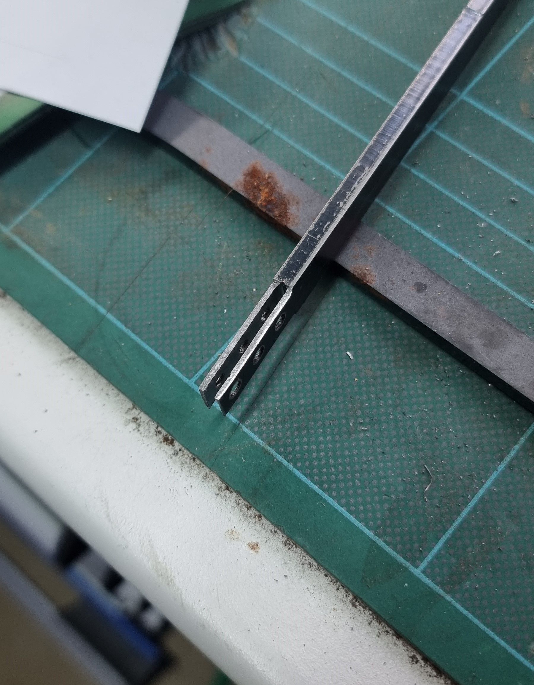
I missed photographing some steps here so will describe what I did plus yet another mistake. This time after finishing the joint end with the extra metal added to the sides and then machined to finish I happily went on to silver solder the extra metal needed at the other end for the fork only to realise after, that I had added the metal to the wrong side of the rod, great for a L/H drive engine but useless for my R/H version. Again, wasting yet more time I sweated the part off, cleaned up and reattached it to the correct side of the rod. No real loss but I clearly need to pay more attention to what I'm doing these days.
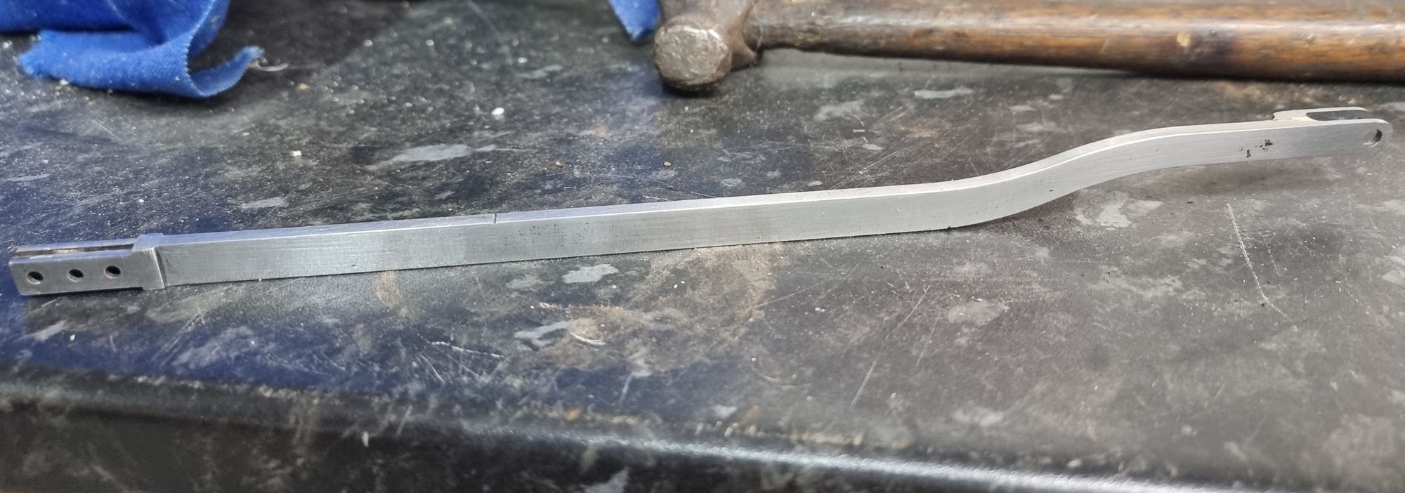
Here we see the finished front section after being cleaned and polished.
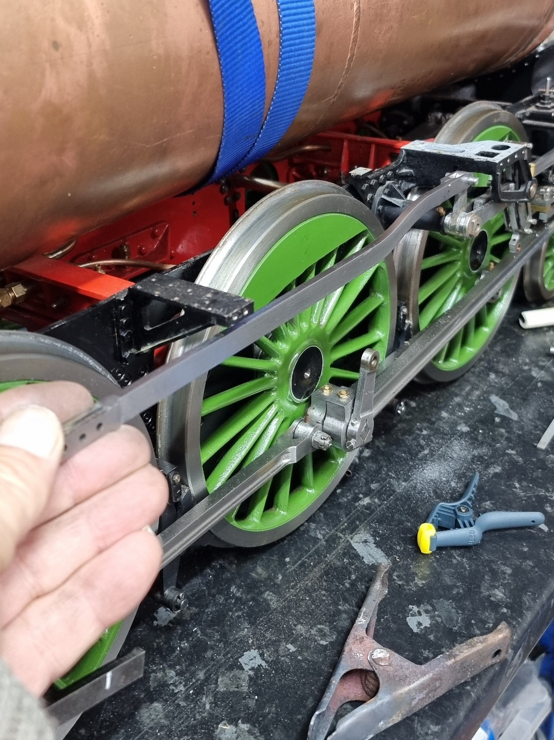
Before moving on to the rear section I first test-fitted the front end to the lifting arm as seen here. All looks good so far, I will need to make the 'hoop' type bracket that's attached to the running board main stay that the rod runs through. I also realised that I needed to finish off the lifting arm as I had yet to fit its taper pin.
Using a couple of clips and checking that both the reverser and lifting arm were in 'mid-gear' I clamped the two reach rod sections together. The reach-rod sections are lining up nicely.
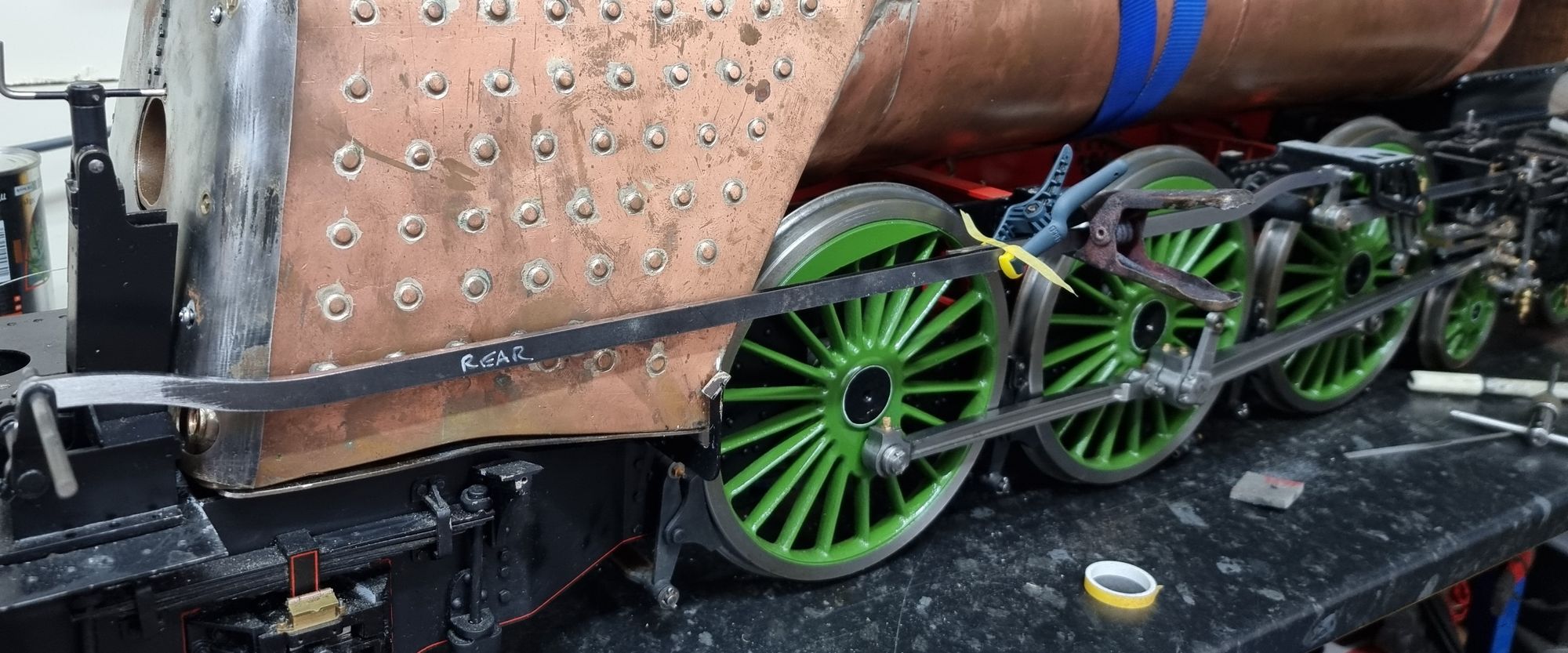
This picture shows the two sections lined up for marking where to cut.
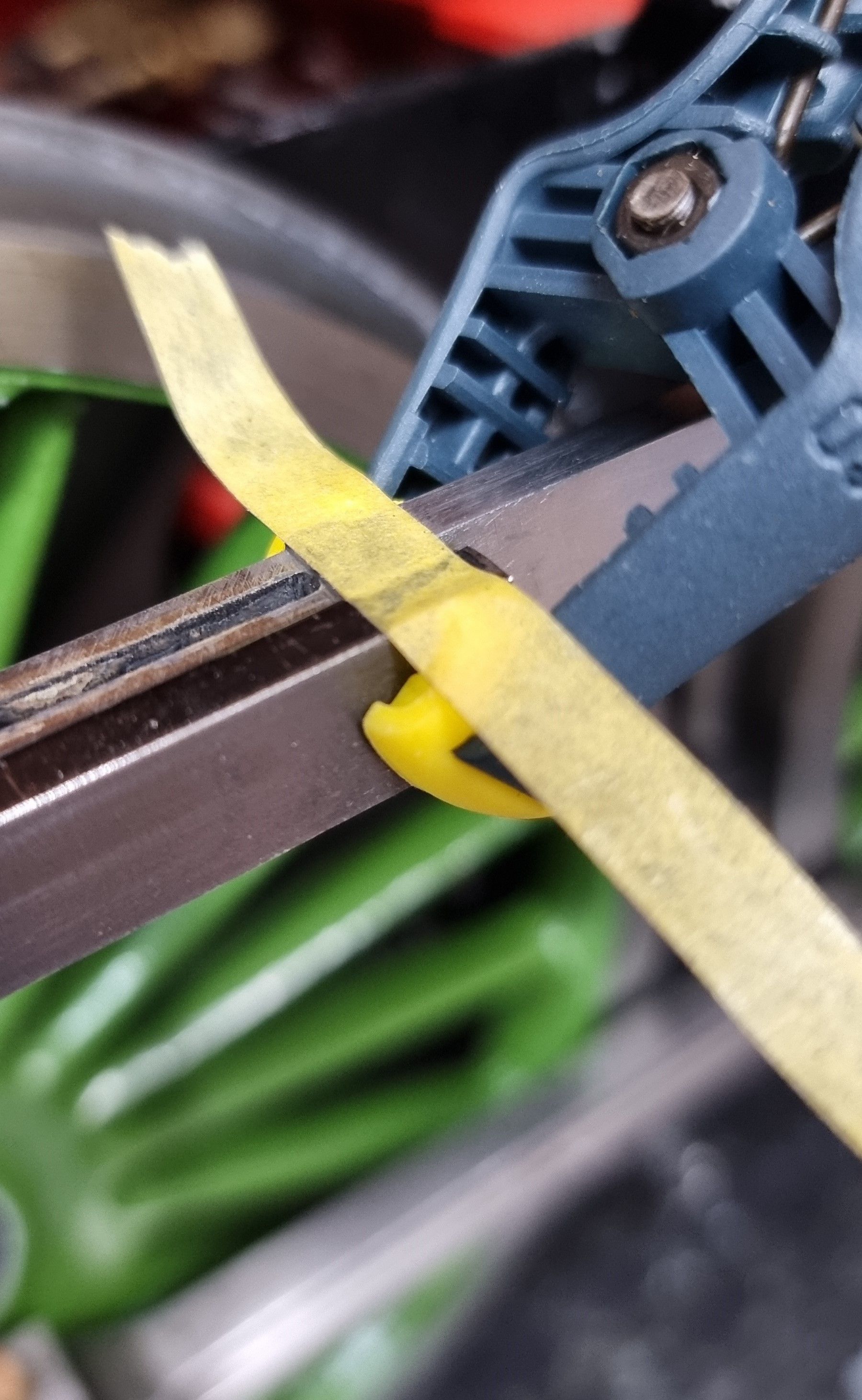
Next time I'll make the rear section, thus completing the reach rod.

