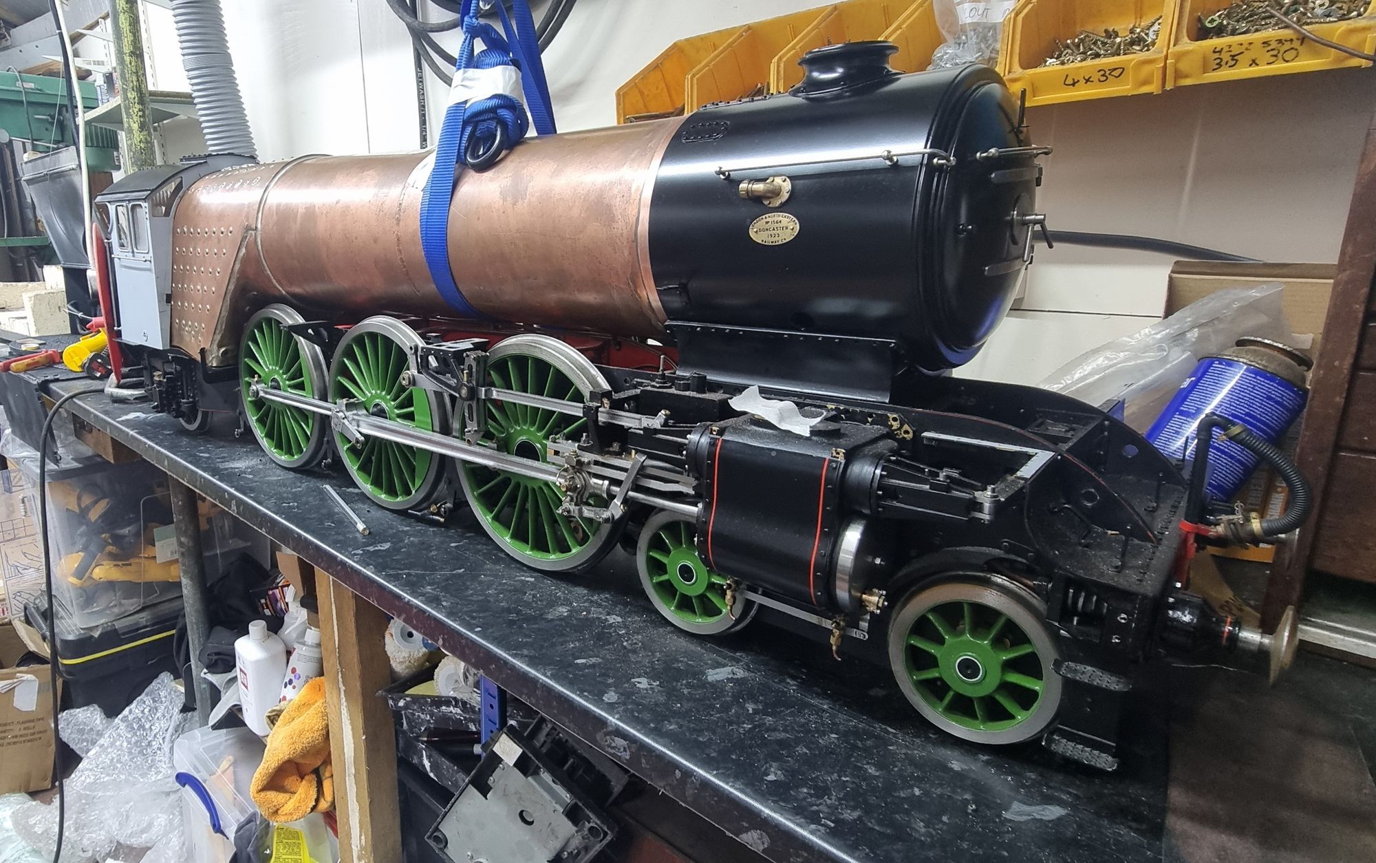
With the reverser nearing completion it was time to take a look at the reach rod, but before doing so, I decided it would be wise to do some checks on the reverser's position, make sure it was correct as the length of the reach rod is very dependent on where the reverser sits.
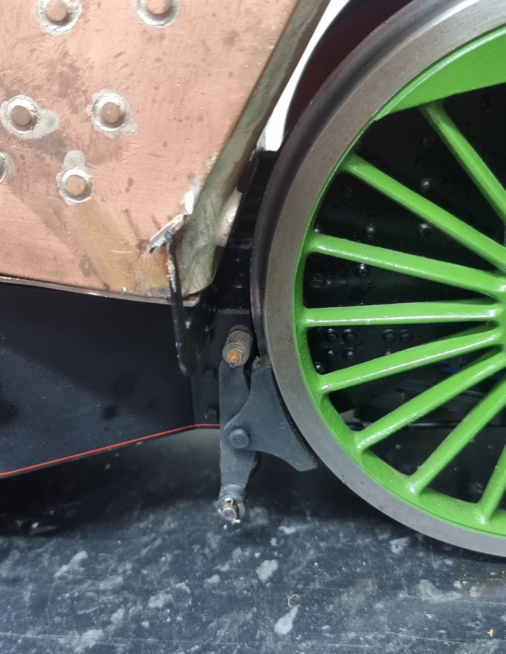
I needed to check a few things such as that the boiler was in its correct position. To do this I needed to temporarily fit the cab and the smokebox to see when added how the boiler sat in relation to the rear main drivers, the ashpan and whether the smokebox was sitting in its correct location on the saddle. I found that the cab was very tight against the manifold bush and at first thought about moving the cab a fraction forward to give room. This worked, and the smokebox could still be fitted in its correct position on the saddle but I wasn't happy until I found out why I had to move the cab.
Eventually, I realised that when fitting the reverser (I followed the info Don gave) to give at least 3/32 clearance from the backhead, he doesn't give any more detail than that other than to state a distance for the shaft fork to be 4.250 from the centreline, nothing for its fore/aft position on the cab floor. The 3/32 measurement is to be sure that the reverser is given enough room for expansion of the boiler once in steam. This I did but I did it before fitting the cleading which of course adds to the back of the boiler, not by much but enough to make an already critical area tighter than it should be.
So the boiler was being forced a little too far forward to clear the reverser, hence, why I moved the cab a little. Everything fitted like this but it wasn't right and I knew that it would always bug me even if not something that anyone was likely to notice, we were only talking a few mm.
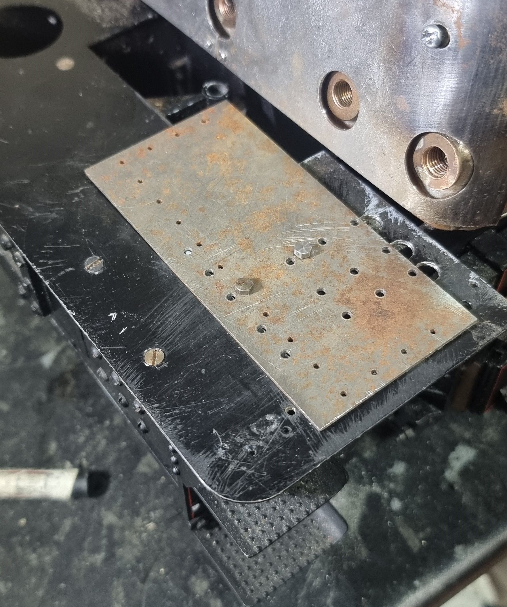
There was only one thing to do and that was to move the reverser back a few mm, this might sound a little daunting at this stage but it isn't if a little thought is given to the method first. My approach (I'm sure you guys will have your own ideas) was to make a drilling jig with the holes drilled to tapping size only and with the job still held in the machine vice to drill the holes to drawing using the DRO. Before removing the part from the vice I drilled two extra holes a few mm forward of two drilled holes along one line, these were drilled to clearance sizes. A bit of a mouthful but hopefully the following picture explains this for me. All I had to do then was drill through the jig and then tap the new 6BA holes. To explain the extra small holes seen, this scrap piece was once the front running board plate as drawn by Don, later research showed this board to be incorrect as the real plate has cut outs along the front edge to fit around the frames. This was covered long ago in the relevant section.
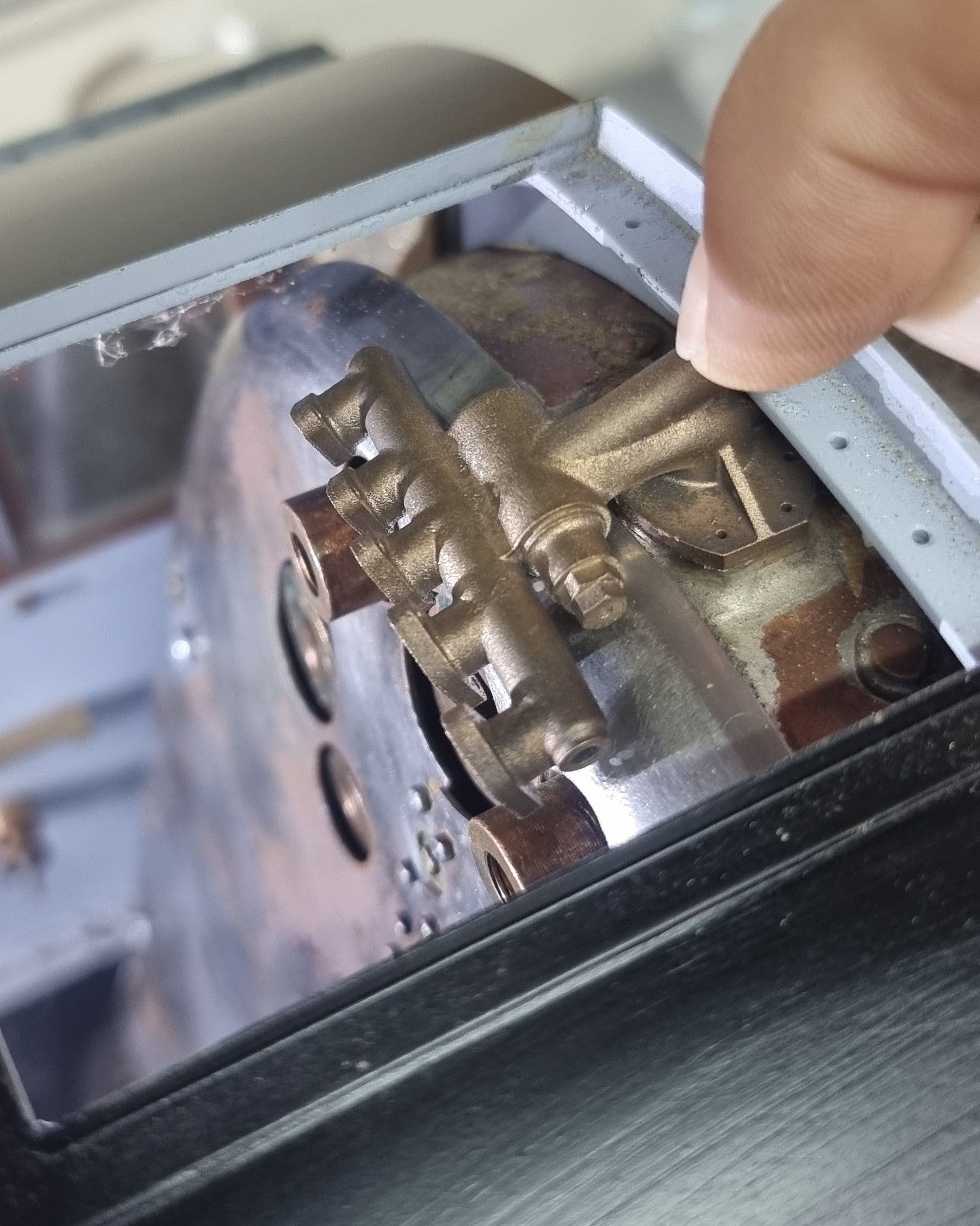
Another check done before doing the above was to dry fit the manifold as it was this part's bush that was sitting a bit close to the spectacle plate. This is a true scale item as will be the other backhead fittings once I get to machining them, all drawings for these were kindly drawn by Adam of Cro Fittings and then cast in NZ by Michael Jack, they are all superb and will enhance the backhead beyond what could be done by hand, a tall order but you'll see why I say this once we get to that stage.
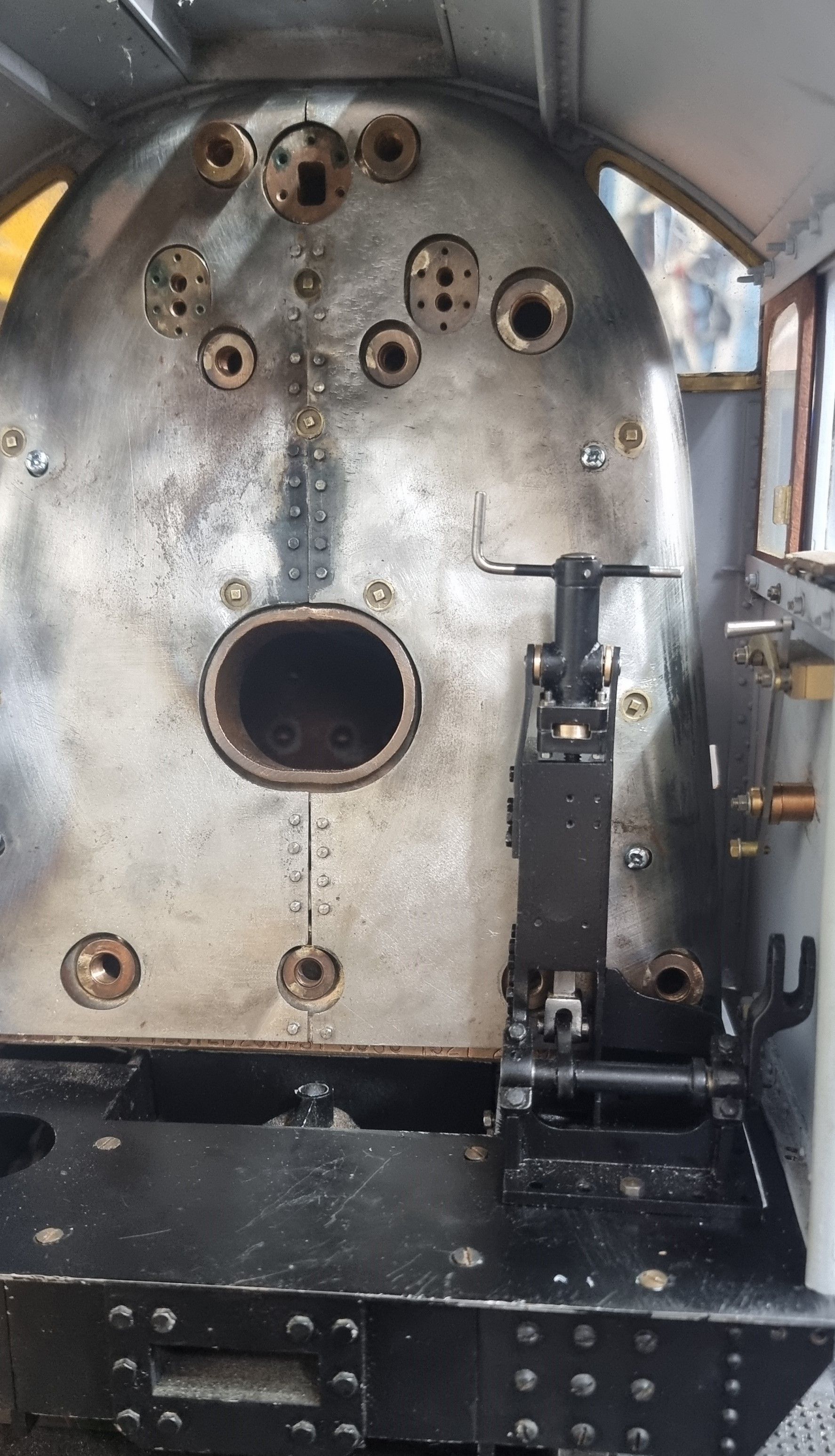
Here we see the reverser now in its new position, much better.
Now that I was happy with the boiler position I placed a mark on the boiler to make it easy to find this position again, after all the boiler will be on and off many times more before it's there for good.
On to the reach rod itself, the two main components were laser cut for me by ED (Model Engineers Laser) many moons ago so most of the boring work has been done. I still need to make the fork on the front section and the sleeve that strengthens the joint. I have a little research left to do here as Don's drawing has left out some important details, hopefully, I'll be fully armed with the knowledge needed asap. Following Don's overall dimensions ( he does say 'check to place') I clamped the two sections together.
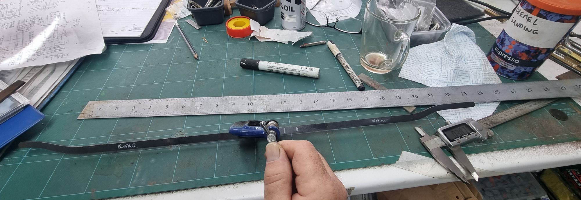
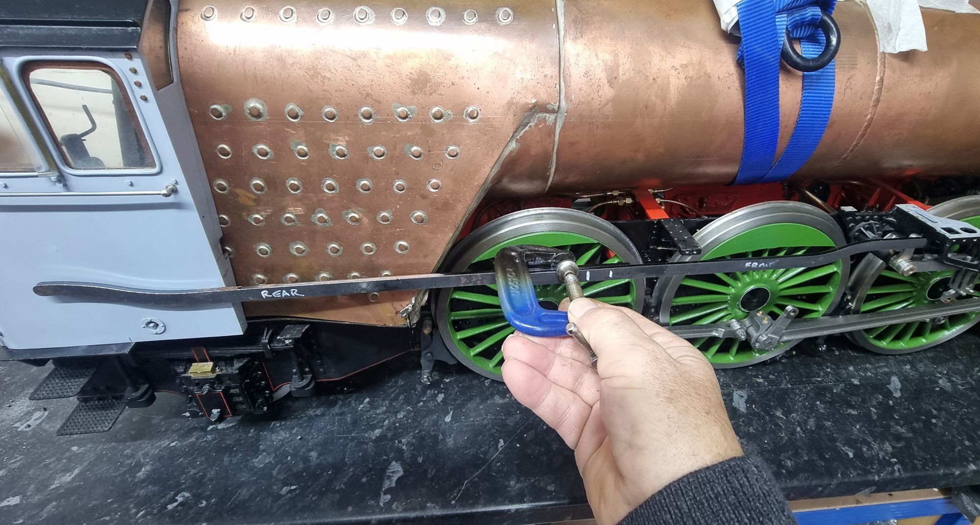
With the two parts clamped I did a quick check alongside the model itself, looks pretty much there to me.
Next time I'll cover the fabrication of the rod itself now that I'm happy with the various pre-checks carried out.

